EP0694020B1 - Machine a rembobiner et procede de formation de rouleaux d'une bande de matiere au moyen d'un dispositif de sectionnement de celle-ci - Google Patents
Machine a rembobiner et procede de formation de rouleaux d'une bande de matiere au moyen d'un dispositif de sectionnement de celle-ci Download PDFInfo
- Publication number
- EP0694020B1 EP0694020B1 EP94912672A EP94912672A EP0694020B1 EP 0694020 B1 EP0694020 B1 EP 0694020B1 EP 94912672 A EP94912672 A EP 94912672A EP 94912672 A EP94912672 A EP 94912672A EP 0694020 B1 EP0694020 B1 EP 0694020B1
- Authority
- EP
- European Patent Office
- Prior art keywords
- web material
- core
- machine according
- rewinding machine
- feeding
- Prior art date
- Legal status (The legal status is an assumption and is not a legal conclusion. Google has not performed a legal analysis and makes no representation as to the accuracy of the status listed.)
- Expired - Lifetime
Links
- 239000000463 material Substances 0.000 title claims abstract description 131
- 230000015572 biosynthetic process Effects 0.000 title claims abstract description 5
- 238000000034 method Methods 0.000 title claims description 5
- 238000003780 insertion Methods 0.000 claims abstract description 21
- 230000037431 insertion Effects 0.000 claims abstract description 21
- 230000033001 locomotion Effects 0.000 claims abstract description 13
- 238000011144 upstream manufacturing Methods 0.000 claims abstract description 8
- 238000004804 winding Methods 0.000 claims description 19
- 230000002093 peripheral effect Effects 0.000 claims description 18
- 239000003292 glue Substances 0.000 claims description 7
- 230000005540 biological transmission Effects 0.000 claims description 6
- 238000005096 rolling process Methods 0.000 claims description 6
- 238000004026 adhesive bonding Methods 0.000 claims description 5
- 230000014759 maintenance of location Effects 0.000 claims description 2
- 230000001133 acceleration Effects 0.000 description 4
- 230000000694 effects Effects 0.000 description 4
- 238000010276 construction Methods 0.000 description 3
- 238000005520 cutting process Methods 0.000 description 3
- 238000004519 manufacturing process Methods 0.000 description 3
- 239000000047 product Substances 0.000 description 3
- 230000008901 benefit Effects 0.000 description 2
- 238000011161 development Methods 0.000 description 2
- 230000007246 mechanism Effects 0.000 description 2
- 230000009471 action Effects 0.000 description 1
- 230000006978 adaptation Effects 0.000 description 1
- 238000013459 approach Methods 0.000 description 1
- 230000008859 change Effects 0.000 description 1
- 238000004033 diameter control Methods 0.000 description 1
- 229910001651 emery Inorganic materials 0.000 description 1
- 239000004744 fabric Substances 0.000 description 1
- 239000012467 final product Substances 0.000 description 1
- 230000002452 interceptive effect Effects 0.000 description 1
- 230000004048 modification Effects 0.000 description 1
- 238000012986 modification Methods 0.000 description 1
- 230000000750 progressive effect Effects 0.000 description 1
- 230000009467 reduction Effects 0.000 description 1
- 238000000926 separation method Methods 0.000 description 1
- 230000035939 shock Effects 0.000 description 1
- 238000012546 transfer Methods 0.000 description 1
Images


Classifications
-
- B—PERFORMING OPERATIONS; TRANSPORTING
- B65—CONVEYING; PACKING; STORING; HANDLING THIN OR FILAMENTARY MATERIAL
- B65H—HANDLING THIN OR FILAMENTARY MATERIAL, e.g. SHEETS, WEBS, CABLES
- B65H19/00—Changing the web roll
- B65H19/22—Changing the web roll in winding mechanisms or in connection with winding operations
- B65H19/2238—The web roll being driven by a winding mechanism of the nip or tangential drive type
- B65H19/2269—Cradle
-
- B—PERFORMING OPERATIONS; TRANSPORTING
- B26—HAND CUTTING TOOLS; CUTTING; SEVERING
- B26D—CUTTING; DETAILS COMMON TO MACHINES FOR PERFORATING, PUNCHING, CUTTING-OUT, STAMPING-OUT OR SEVERING
- B26D2210/00—Machines or methods used for cutting special materials
- B26D2210/11—Machines or methods used for cutting special materials for cutting web rolls
-
- B—PERFORMING OPERATIONS; TRANSPORTING
- B65—CONVEYING; PACKING; STORING; HANDLING THIN OR FILAMENTARY MATERIAL
- B65H—HANDLING THIN OR FILAMENTARY MATERIAL, e.g. SHEETS, WEBS, CABLES
- B65H2301/00—Handling processes for sheets or webs
- B65H2301/40—Type of handling process
- B65H2301/41—Winding, unwinding
- B65H2301/417—Handling or changing web rolls
- B65H2301/418—Changing web roll
- B65H2301/4181—Core or mandrel supply
- B65H2301/41812—Core or mandrel supply by conveyor belt or chain running in closed loop
-
- B—PERFORMING OPERATIONS; TRANSPORTING
- B65—CONVEYING; PACKING; STORING; HANDLING THIN OR FILAMENTARY MATERIAL
- B65H—HANDLING THIN OR FILAMENTARY MATERIAL, e.g. SHEETS, WEBS, CABLES
- B65H2406/00—Means using fluid
- B65H2406/10—Means using fluid made only for exhausting gaseous medium
- B65H2406/11—Means using fluid made only for exhausting gaseous medium producing fluidised bed
- B65H2406/112—Means using fluid made only for exhausting gaseous medium producing fluidised bed for handling material along preferably rectilinear path, e.g. nozzle bed for web
-
- B—PERFORMING OPERATIONS; TRANSPORTING
- B65—CONVEYING; PACKING; STORING; HANDLING THIN OR FILAMENTARY MATERIAL
- B65H—HANDLING THIN OR FILAMENTARY MATERIAL, e.g. SHEETS, WEBS, CABLES
- B65H2408/00—Specific machines
- B65H2408/20—Specific machines for handling web(s)
- B65H2408/23—Winding machines
- B65H2408/235—Cradles
-
- B—PERFORMING OPERATIONS; TRANSPORTING
- B65—CONVEYING; PACKING; STORING; HANDLING THIN OR FILAMENTARY MATERIAL
- B65H—HANDLING THIN OR FILAMENTARY MATERIAL, e.g. SHEETS, WEBS, CABLES
- B65H2513/00—Dynamic entities; Timing aspects
- B65H2513/10—Speed
Definitions
- the invention refers to a surface rewinding machine and method for the formation of logs or rolls of web material wound on a central core.
- Such rewinding machines are well-known, described, for example, in U.S. Patents No. 4,487,377; 4,723,724; 4,327,877 and 4,828,195; U.K. Patent No. 2,105,688; and in EP-A-0 489 039.
- the present invention refers to a rewinding machine which includes a first winder roller on which the web material is fed; a second winder roller defining, with the first winder roller, a nip through which the core and the web material pass; means for feeding the web material to said nip; means for introducing a core on which the web material is to be wound; and a web material severing means cooperating with said first winder roller.
- a rewinder of this type is described, for example, in U.S. Patent 4,487,377.
- These rewinders are used for producing smaller-diameter logs or rolls of web material from large-diameter parent rolls.
- these machines are used in the paper converting industry to produce rolls of toilet paper, kitchen towels, all-purpose wipers and the like.
- the formed logs may be as long as 350 cm and only 10-15 cm in outer diameter, and are subsequently cut transversely to their axis to obtain small rolls which may be only 10-30 cm long.
- U.S. Patent 4,487,377 provides for a web-cutting member which cooperates with the first winder roller of the rewinder.
- the web material is cut upstream of the point where the core is introduced. After cutting, the leading edge of the web material adheres to the surface of the winder roller and is transferred (by the rotation of the latter) towards the winding region where the leading edge is made to adhere to a new core suitably introduced by an insertion means.
- This machine requires means (for holding the leading edge of the web material onto the winder roller) which are housed inside the winder roller and which must be timely activated and deactivated to hold and release the edge at preset moments, thereby allowing the starting of the winding on a new core.
- a first object of the present invention is a rewinding machine which is able to produce a high-quality finished product at high speeds with a simpler and more economical construction than that of known rewinders.
- a further object of the present invention is to provide a versatile rewinder able to produce logs of varying length without requiring complex mechanisms for adaptation to different lengths of web material without a slipping of the web material on the winder roller onto which it is fed.
- Another object of the present invention is the construction of a rewinder having means for tearing or cutting the web material, which means are reliable, simple, and inexpensive to produce and maintain.
- a surface or track is provided upstream of the nip between the winder rollers, which defines, together with the web feeding means which feeds the web material into the nip, a channel into which the core is introduced.
- a web-severing means cooperates with said web feeding means at an intermediate position along said channel between the region of insertion of the new core and the nip defined between the winder rollers.
- a machine wherein a core is inserted into a channel upstream of the nip between a first and a second winder roller.
- the web material is severed downstream of the core insertion region by severing means which cooperate with the first winder roller or other means for feeding the material into the nip. This avoids the need of accelerating one of the winder rollers, and the severed web material begins to wind up on the core while the core starts to roll into the channel and on the surface or track by the rotation of the first winder roller.
- the web-feeding means may be a belt system combined with said first winder roller.
- This arrangement allows a precise severance of the web material to be carried out by severing means which cooperate with the first winder roller, without having to hold the leading edge of the web material on the winder roller, inasmuch as at the moment of severance of the web material, the new core is already in contact with the web material. Furthermore, the un-tensioning of the web material upstream of the winding region is substantially eliminated.
- the start of the winding of the web material around the core may be assisted by placing glue on the surface of said core, or by suitable air jet or vacuum or mechanical means.
- glue ensures a more reliable operation and increases the quality of the final product.
- the surface or track for the rolling of the core extends, substantially, from the position where the introduction means discharges the core, up to the nip between the two winder rollers.
- said surface is preferably comb-shaped, at least in the terminal portion thereof. This comb-like terminal portion cooperates with annular slots in the second winder roller to allow the core, having the first turns of web material wound thereon, to be transferred smoothly and without shocks or strains to the nip between the winder rollers.
- the track or fixed surface can define, together with the cylindrical surface of the first winder roller, a channel of substantially uniform cross-section and, advantageously, of a height slightly lower than the diameter of the core.
- the difference between the height of the channel and the diameter of the core causes the latter to be slightly squeezed when initially inserted thereinto, and this advantageously allows the web material to adhere to the core while facilitating the rotational acceleration of said core.
- the severing means are so constructed as to be able to move along a cylindrical path which is almost tangent to the cylindrical surface of the first winder roller, or slightly interfering therewith.
- the peripheral speed of the cylindrical surface of the first winder roller and of the web material carried thereon is higher than the tangential speed of the severing means along said path.
- the rotational speed of the unit which carries the severing means is precisely controlled. Perforation lines on the web material adjacent the severing means will facilitate the tearing of the web material.
- the severing means In order for the severing means to enter in contact with the web on the cylindrical surface of the first winder roller at an intermediate position along the said channel, (while the rotary unit carrying the severing means is arranged outside the channel), the severing means pass through slots or apertures in said track.
- the severing means By controlling the rotational speed of the unit, the severing means moves out of the channel ahead of the core which is passing therethrough.
- the apertures or slots in the track may be obtained, for example, by providing a plurality of strips parallel to one another in the direction of advancement of the web material. The distance between the strips is sufficient to allow the passage of the severing means.
- the severing means are made in the form of pressers or pads (resilient, if required) which press against the surface of the first winder roller, or other material feeding means, to pinch the web material.
- the surface of the first winder roller may have a low coefficient of friction.
- the first winder roller may be provided with a surface having wide annular bands suitably polished, having a low coefficient of friction, and separated by narrow annular strips having a high coefficient of friction. This ensures the proper friction on the web to properly feed said web, in particular at the moment when the new core is rotationally accelerated.
- the annular strips with high coefficient of friction may be aligned with the strips which define the track or core rolling surface.
- the length of the material wound into each individual log may be pre-determined and accurately controlled, regardless of the diameter or circumference of the first winder roller, inasmuch as there is no need for coordinating the position of the severing means with a particular portion of the surface of the winder roller, as is the case in the prior art machines.
- the severing means are provided with blade portions (saw-toothed, if required) which cooperate with annular channels in the first winder roller.
- Blade means could operate with a longitudinal slot instead of annular channels.
- the unloading from the winder of a completed log or roll may take place by an accelerating third, diameter-control, roller disposed downstream of the first and second winder rollers, in a manner similar to that described in the above-mentioned GB-A-2,105,688.
- provision may also be made for the completed log to be unloaded by deceleration of the second winder roller, while keeping the peripheral speed of the third winder roller constant and substantially equal to the peripheral speed of the first winder roller.
- the deceleration of the second winder roller also causes the core to go through the nip defined by the first and second winder rollers.
- the core passes through the nip between the first and second winder rollers by means of a small and constant difference in the peripheral speed between said two winder rollers. In this case, it may be necessary to provide a relative mobility of the first and second winder rollers.
- an actuator means may be provided which causes both the deceleration of said roller and the actuation of the web material severing means. This is possible because the latter will have to be operated only when a log has been completed and a new core has to be introduced, i.e., when the deceleration of the second winder roller is necessary. This greatly simplifies the structure of the machine.
- Reference numerals 1 and 3 indicate rollers around which the web material N is fed from a supply parent roll (not shown) to the winding region of the rewinder.
- the web material N is fed through a perforation group, generally shown at 5, including a non-rotating support 7 and a rotating cylinder 9.
- the support 7 carries a counter-blade 11 which cooperates with blades 13 carried by the cylinder 9 to provide a line of perforations across the web.
- first winder roller 15, around which the web material is fed Located downstream of the perforation group 5 are a first winder roller 15, around which the web material is fed, and a second winder roller 17.
- the two rollers 15 and 17 each rotates in a counter-clockwise direction.
- the cylindrical surfaces of rollers 15 and 17 define a nip 19 through which the web material N is fed.
- Numeral 21 designates a third roller also rotating in a counter-clockwise direction and supported by an arm 23 pivoted at 25 to the machine frame.
- the arm 23 can oscillate to allow the roller 21 to be lifted and lowered by an actuator 27.
- the winder rollers 15, 17 and 21 define the region where the winding of each log is completed, according to the procedures to be described hereinafter.
- a chute 31 Located downstream of the three winder rollers is a chute 31 along which the completed logs L roll for the transfer thereof towards tail gluer means, not shown.
- a curved surface or track 33 Disposed upstream of the nip 19 is a curved surface or track 33 defined by a series of parallel arcuate strips 35 (Fig. 9).
- the strips 35 have pointed ends 36 directed toward the nip 19 and which terminate in annular slots 37 of the lower winder roller 17. (See Figs. 10, 11 and 12).
- the strips 35 terminate near the region at which the introduction of the cores A takes place, the latter being fed and inserted in the manner described hereinafter.
- the curved surface or track 33 and the cylindrical surface of the first winder roller 15 define a channel 39 for the passage of the cores A.
- the cross-section i.e., the dimension of the channel 39 measured perpendicularly to the track 33, may be substantially uniform along the length of the strips and advantageously equal to, or slightly less than the diameter of the cores being used. This is achieved because the surface of the track 33 has a constant radius of curvature with its axis coincident with the axis of the winder roller 15.
- a rotary unit 41 carrying means 43 for the severance of the web material, which cooperate with the cylindrical surface of the winder roller 15.
- the severing means includes pressers or pads 43 intended to exert a pressure, through a slight interference, against the surface of the roller 15.
- the unit 41 is made to rotate intermittently, in the illustrated example, in a clockwise direction.
- the pressers 43 move along a circular path C which has an axis coincident with the axis of rotation 45 of the unit 41 and almost tangent to (or making a slight interference with) the cylindrical surface of the winder roller 15.
- the cores are introduced into the channel 39 by means of a conveyor generally shown at 47 (see Fig. 1).
- the conveyor includes a flexible continuous member 49 made up, for example, of a chain or a belt driven around transmission wheels 51, 53, 55, one of which is motor-driven. Disposed at regular intervals on the flexible member 49 are pushers 57 each of which picks up a core from a container 59.
- the cores A are removed by the pushers 57 and lifted and transferred, through a gluing unit, generally shown at 61, which may include a tank 63 of glue in which a series of discs 65 rotate.
- gluers are well-known and need not be described in greater detail.
- Fig. 1 only a few cores A are shown, but it is to be understood that, under proper operating conditions, a respective core A is carried by each pusher 57 from the container 59, across the wheel 51 to the wheel 55, close to the mouth of the channel 39, to start the winding of each log, as will be described hereinafter with reference to Figs. 2 to 8.
- Fig. 2 shows the final step of the winding of a log L.
- the first winder roller 15 and the third roller 21 rotate at a peripheral speed equal to the web material N feeding speed, while the second winder roller 17 rotates at a temporary lower peripheral speed to allow the completed log L to be moved towards the chute 31.
- a new core A1 has been brought by the relevant pusher 57 to the entrance of channel 39.
- the insertion of the core A1 into the channel 39 may be carried out directly by the relevant pusher 57, or by an auxiliary pushing member, indicated by 67, rotating about the axis of wheel 55.
- the latter solution (shown in the illustrated example) allows the insertion of the core A to be performed with greater rapidity and precision, inasmuch as the insertion movement is unrelated to the movement of conveyor 47, the push member 67 being provided with an actuator which is independent of the actuator of the conveyor 47.
- the rotary unit 41 rotates about its axis 45 and the pressers 43 have already entered the channel 39 by passing between the strips 35 which define the surface 33.
- the peripheral speed of pressers 43 is less than that of roller 15 and, therefore, also less than the speed of the web material N. In this way, the web material N is pressed between the two surfaces moving at different speeds.
- the effect of this difference in speed is a slowing down of the pinched portion with respect to the rest of the web material. This slowing down causes the web material to tear along the perforation line which is closest to the point at which the web material N is pinched.
- Fig. 3 shows the next stage in which the web material is torn off, giving rise to a new leading edge NL.
- the core A1 has, in the meantime, started to rotate owing to the contact thereof with the stationary surface 33 and with the rotating cylindrical surface of the winder roller 15.
- the core moves forward (i.e., downstream), therefore, by rolling along surface 33 at a speed equal to half the feeding speed of the web material N.
- the cross dimension of channel 39 which is slightly less than the diameter of the core A1 (the latter being typically made from pliable cardboard), allows a friction to be generated. This friction is necessary for the angular acceleration of the core from zero to the rolling speed, and the adhesion of the web material N to the surface of said core, on which glue has been spread by the gluing device 61. The latter effect is missing when the gluing of the core is not provided.
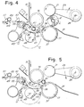
- Fig. 4 shows the relative position taken by the core A and pressers 43 a few moments after severance of the web material N.
- the rotary unit 41 keeps on rotating at a speed lower than the web feeding speed, and also less than the advancing speed of core A1, so that a progressive approach of the core to the pressers 43 will take place. However, contact between core and pressers is avoided since a slight rotation of the rotary unit 41, causes the presser means move out of the channel 39 through the spaces between the strips 35. This allows the core A1 to roll forward up to the nip 19 as shown in Fig. 5.
- the core has left the surface 33 and is in contact with the surfaces of the winder rollers 15 and 17 which, by rotating at slightly different speeds (roller 17 being slower), cause the core to move forward through the nip 19.
- the core will be located between the three rollers 15, 17 and 21, and the web material N will continue to wind up on the core, some turns thereof having already been wound during the transit of the core through the channel 39 and the nip 19.
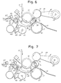
- the unit 41 keeps on rotating in clockwise direction until it reaches the position in Fig. 6 where it stops until the next operating cycle.
- the auxiliary pushing member 67 which has continued to rotate simultaneously with the unit 41, is stopped at the angular position shown in Fig. 6.
- the log L is shown in an intermediate winding step between the rollers 15, 17 and 21, the movable roller 21 being gradually moved upwards to allow the controlled increase of the log.
- the conveyor 47 keeps on moving forward thus bringing the next core A2 to the inlet of channel 39, as can be seen in the next Fig. 7.
- the conveyor 47 may be provided with either continuous or intermittent motion, also in relation to the rewinder speed.
- Fig. 8 shows the almost completed log L, the core A2 being brought by the pusher 57 to the inlet of channel 39 and held in that position by a resilient retention finger 71. The latter prevents the core A2 from rolling down and coming in contact with the web material N before the rotary unit 41 is in place.
- FIG. 8 illustrates the sequence of operations in which the contact between the new core A1 and the web material N takes place an instant before the material N is torn off, and precisely the moment in which the contact between the pressers 43 and the material N begins.
- the contact between the core A1 and the web material N may also be controlled to take place simultaneously with the tear, or with some delay.
- the regions 15A and 15B have annular development, it is possible to have the contact between the roller 15 and the pressers 43 at any point along the periphery of the roller 15. This allows the web material N to be severed at any moment, and thus an amount of web material N (accurately presettable independently of the circumferential development of the roller 5) to be wound on each log.
- severing means of different type may also be used.
- Fig. 10 shows severing means 43 having sharp, saw-toothed blades 43A which cooperate with annular slots 15C provided in the surface of roller 15. The difference in speed between the blades 43A and the surface of the roller 15 causes the web material to tear. Also, in this case, there is no limitation between the angular position of the roller 15 and the position in which the severing means 43 operate.
- Fig. 11 shows, instead, a solution in which the blades 43A cooperate with a longitudinal (i.e., axial) slot 15D formed in the surface of roller 15.
- the slot 15D is of a size which is sufficient to avoid interference between the two elements.
- this embodiment has the advantage of avoiding mutual mechanical contact between the severing means and the winder roller 15.
- a relation does exist between the angular position of the roller 15 and the position of the severing means 43, 43A. This imposes limits to the machine's versatility.
- the length of the web material wound on each log may vary only according to multiples of the circumference of roller 15, unless a mutual sliding between the web material N and the roller 15 is provided during winding of each log, with consequent cyclical rephasing of the position of the slot 15D and severing means 43, 43A.
- Figs. 10 and 11 are particularly suitable in case the rewinder has no perforation group 5. In this case, the rupture of the web material occurs where the serrated and/or sharpened blades are inserted.
- a synchronism must be suitably provided between the action of the severing means 43 and the position of the perforation line, so that the contact between the web material N and the severing means occurs in close proximity to a perforation line with the latter lying immediately downstream of the region of contact.
- a control unit schematically shown at 2 to which data of angular position relative to the position of the cylinder 9 is supplied.
- the control unit 2 operates an actuator 75 which, as described hereinafter, controls the operation for the severance of the web material, as well as the insertion of the new core and the unloading of the log in synchronism with the position of the perforation line.
- the same control unit 2 may control the actuator 27 which moves the roller 21 up and down.
- Fig. 12 schematically shows a particularly advantageous example of the actuator and the drive means which control the motion of the web material severing means and core insertion means and the deceleration of the winder roller 17.
- Fig. 12 is a section taken on the line XII-XII of Fig. 1 from which the parts having no significant relation with the description of the means for the actuation of the rotary unit 41 have been taken away.
- Numeral 75 indicates a motor serving as actuator of the rotary unit 41.
- a first toothed pulley 79 over which a toothed belt 81 is driven, the latter transmitting the motion to the rotary unit 41 via another pulley 83.
- a second toothed pulley 85 keyed on the shaft 77, transmits the motion, via a toothed belt 87, to a toothed pulley 89.
- the pulley 89 is keyed on a first input axle of a differential gear generally shown at 91.
- a pulley 93 Fixed to the gear-holding case or box of the differential gear 91 is a pulley 93 on which a belt 95 is driven, the latter taking its motion from a machine member, not shown, rotating at a speed proportional to the feeding speed of the web material N.
- Said member may be any one of the web material-guiding and feeding rollers, such as the roller 15.
- Numeral 97 designates the output axle of the differential gear 91. Keyed on said output axle is a toothed pulley 99 which, through a toothed belt 101, transmits the motion to a toothed pulley 103 keyed on the shaft of the second winder roller 17.
- Also keyed on the rotary unit 41 is another pulley 105 which, through a belt 107, transmits the motion to a pulley 109 keyed on the shaft 68 which carries the auxiliary pushing member 67.
- the motor 75 In the winding stage of the log L between the rollers 15, 17 and 21 (i.e., in the stage shown in Figs. 6 and 7), the motor 75 is at a standstill.
- the winder roller 17 is rotated directly by belt 95.
- the transmission ratio of the differential gear and of the pulleys is such as to achieve a peripheral speed of the roller 17 equal to the peripheral speed of the roller 15.
- the motor 75 is rotated.
- a single actuator (motor 75) makes it possible to operate the severance of the web material, the insertion of a new core and the discharge of a completed log, by use of an extremely simple and economical mechanism.
- Fig. 13 shows a modified embodiment in which the channel 39 is not formed by the surface of a first winder roller, but by a separate web feeding means consisting of a plurality of belts 150 driven between a first winder roller 15, and an auxiliary cylinder 152, said belts being suitably spaced apart in the axial direction.
- Numeral 33 again indicates the surface defining, together with the belt system 150, a channel 39.
- the second and third winder rollers are again designated 17 and 21, respectively.
- Numeral 41 indicates the rotary unit carrying the severing means 43 which move through the slits between the strips 35 which define the surface 33.
- the core insertion means have been omitted in the drawing for the sake of clarity.
- the surface 154 is a surface which the belts 150 contact.
- the surface 154 may have a plurality of sliding seats for the belts 154, so that the severing means 43 (consisting of pressers or other means, as described above) act on an almost continuous transverse surface.
- the surface 54 may be made of a material having low coefficient of friction to facilitate both the sliding of the belts 152 and the tearing of the web material.
- the belts 152 are located in alignment with the strips 35 which define the surface 33, and the pressers 43 pass between adjacent belts 150.
- the interruption means may comprise blade means which cut the web material, in a similar way as provided by the means 43A.
- the speed of means 43, 43A may also be equal to the speed of the web material N, as the separation thereof is performed by a cutter (means 43A) or a counteracting stationary surface (154).
Landscapes
- Replacement Of Web Rolls (AREA)
- Making Paper Articles (AREA)
- Advancing Webs (AREA)
- Winding, Rewinding, Material Storage Devices (AREA)
- Winding Of Webs (AREA)
- Preliminary Treatment Of Fibers (AREA)
Abstract
Claims (36)
- Rembobineuse pour la formation de rouleaux (L) d'un matériau en bande (N) enroulé sur un tube (A), comprenant :- un premier tambour d'enroulement (15) sur lequel le matériau en bande est amené,- un deuxième tambour d'enroulement (17) définissant, avec le premier tambour d'enroulement, un étranglement (19) à travers lequel passent le tube (A) et le matériau en bande (N),- des moyens (15; 150) pour alimenter l'étranglement (19) en matériau en bande (N), qui ont une vitesse d'avancement sensiblement égale à la vitesse d'amenée du matériau en bande (N),- des moyens d'insertion (47 ; 57 ; 67) pour introduire dans l'étranglement un tube sur lequel le matériau en bande va être enroulé,- des moyens de sectionnement (43 ; 43A) coopérant avec les moyens d'alimentation,
caractérisée en ce que- en amont de l'étranglement (19) par rapport à la direction d'alimentation du matériau en bande (N) se trouve une surface (33) définissant avec les moyens (15; 150) d'alimentation en matériau en bande (N), un canal (39) dans lequel le tube (A) est inséré, le tube dans le canal étant en contact avec la surface (33) et le matériau en bande apporté par les moyens d'alimentation, la vitesse des moyens d'alimentation (15; 150) obligeant le tube à avancer le long du canal (39),- les moyens (43 ; 43A) pour sectionner le matériau en bande coopèrent avec les moyens d'alimentation (15; 150) dans une position intermédiaire le long du canal, le matériau en bande étant sectionné entre la région d'insertion d'un nouveau tube et l'étranglement (19). - Rembobineuse selon la revendication 1, caractérisée en ce que les moyens pour alimenter l'étranglement (19) en matériau en bande (N) sont constitués de la surface cylindrique du premier tambour d'enroulement (15), et que de plus la surface (33) définissant le canal (39) est d'une surface courbée.
- Rembobineuse selon la revendication 1, caractérisée en ce que les moyens pour alimenter l'étranglement (19) en matériau en bande (N) comprennent un système à convoyeur avec des organes flexibles (150) guidés autour du premier tambour d'enroulement (15).
- Rembobineuse selon la revendication 2, caractérisée en ce que la surface (33) définissant le canal (39) est une surface concave ayant un centre de courbure coïncidant avec le centre de rotation du premier tambour d'enroulement (15), la hauteur du canal (39) étant égale ou légèrement inférieure au diamètre du tube.
- Rembobineuse selon la revendication 3, caractérisée en ce qu'on trouve une surface de contre-réaction (154) en association avec les organes flexibles (150).
- Rembobineuse selon une ou plusieurs des revendications précédentes, caractérisée en ce que la surface (33) commence en un point adjacent où les moyens d'insertion (67) relâchent le tube et se terminent près de l'étranglement (19).
- Rembobineuse selon une ou plusieurs des revendications précédentes, caractérisée en ce que les moyens de sectionnement (43 ; 43A) se déplacent le long d'un trajet (C) qui est approximativement tangent aux moyens d'alimentation de l'étranglement en matériau en bande, et en ce que durant la coopération entre les moyens de sectionnement et les moyens d'alimentation, la vitesse d'alimentation du matériau en bande et celle des moyens d'amenée (15 ; 150) est plus grande que la vitesse périphérique des moyens de sectionnement, la différence entre les vitesses créant une tension et ainsi un déchirement du matériau en bande entre le rouleau formé (L) et la région de contact entre le matériau en bande et les moyens de sectionnement.
- Rembobineuse selon l'une des revendications 1 à 6, caractérisée en ce que les moyens de sectionnement (43; 43A) se déplacent le long d'un trajet (C) qui est approximativement tangent aux moyens d'alimentation de l'étranglement en matériau en bande, en ce que durant la coopération entre les moyens de sectionnement et les moyens d'alimentation, la vitesse d'alimentation du matériau en bande (N) est approximativement égale à la vitesse périphérique des moyens de sectionnement, les moyens de sectionnement portant des organes en forme de lame pour sectionner le matériau en bande.
- Rembobineuse selon une ou plusieurs des revendications précédentes, caractérisée en ce que la surface (33) définit avec les moyens d'alimentation (15; 150) un canal de section transversale presque uniforme.
- Rembobineuse selon une ou plusieurs des revendications précédentes, caractérisée en ce que la surface (33) présente une partie terminale en forme de peigne (36) dont les dents se terminent dans des fentes annulaires (37) dans la surface du deuxième tambour d'enroulement (17).
- Rembobineuse selon une ou plusieurs des revendications précédentes, caractérisée en ce que la surface (33) est définie par une pluralité de bandes (35) approximativement parallèles les unes aux autres et s'étendant dans la direction d'alimentation en matériau en bande.
- Rembobineuse selon la revendication 11, caractérisée en ce que le premier tambour d'enroulement présente, sur sa surface cylindrique, des régions annulaires (158) ayant des hauts coefficients de friction, disposées en alignement avec les bandes parallèles (35) définissant cette surface (33).
- Rembobineuse selon une ou plusieurs des revendications précédentes, caractérisée en ce que les moyens de sectionnement (43 ; 43A) sont portés par une unité rotative (41) disposée à l'extérieur du canal (39) défini par la surface (33), les moyens de sectionnement pénétrant dans le canal par des ouvertures ménagées dans la surface (33).
- Rembobineuse selon une ou plusieurs des revendications précédentes, caractérisée en ce que les moyens de sectionnement (43) comprennent des organes de pression (43) qui coopèrent avec les moyens d'alimentation en matériau.
- Rembobineuse selon la revendication 14, caractérisée en ce que les organes de pression (43) sont élastiques.
- Rembobineuse selon la revendication 14 ou 15, caractérisée en ce que la surface des organes de pression qui coopèrent avec les moyens d'alimentation a un haut coefficient de friction.
- Rembobineuse selon la revendication 9, caractérisée en ce que les organes de pression (43) coopèrent avec des portions de surface des moyens d'alimentation (15; 150) ayant des bas coefficients de friction.
- Rembobineuse selon l'une des revendications 1 à 13, caractérisée en ce que les moyens de sectionnement sont munis d'éléments en forme de lame (43A) qui coopèrent avec des canaux correspondants (15C ; 15D) dans les moyens d'alimentation en matériau (15 ; 150).
- Rembobineuse selon la revendication 18, caractérisée en ce que les canaux sont des canaux annulaires (15C).
- Rembobineuse selon la revendication 18, caractérisée en ce que les canaux sont des canaux longitudinaux (15D) s'étendant sensiblement parallèlement à l'axe du premier tambour d'enroulement (15).
- Rembobineuse selon une ou plusieurs des revendications précédentes, caractérisée par des moyens (75, 91) pour contrôler la vitesse du deuxième tambour d'enroulement, qui maintiennent la vitesse périphérique du deuxième tambour d'enroulement (17) à une valeur inférieure à la vitesse périphérique du premier tambour d'enroulement (15), au moins durant le transit du tube à travers l'étranglement (19).
- Rembobineuse selon la revendication 21, caractérisée en ce que les moyens de contrôle de la vitesse (75, 91) provoquent une décélération temporaire du deuxième tambour d'enroulement (17) pour permettre le transit du tube à travers l'étranglement.
- Rembobineuse selon la revendication 22, caractérisée en ce qu'elle comprend des moyens d'actionnement (75) pour actionner les moyens de sectionnement (43), qui provoquent, simultanément avec le fonctionnement des moyens de sectionnement, une décélération temporaire du deuxième tambour d'enroulement.
- Rembobineuse selon la revendication 23, caractérisée en ce que l'on trouve associé avec le deuxième tambour d'enroulement (17) un engrenage épicyclique (91) muni de deux entrées et d'une sortie, la sortie conduisant le deuxième tambour d'enroulement (17) en rotation, une première entrée (93) étant connectée avec des moyens de transmission (95) qui ont un mouvement proportionnel à la vitesse d'amenée du matériau en bande (N), et la deuxième entrée (89) étant connectée aux moyens d'actionnement (75) qui actionnent les moyens de sectionnement (43 ; 43A).
- Rembobineuse selon une ou plusieurs des revendications précédentes, caractérisée en ce qu'elle comprend des moyens d'encollage (61) qui appliquent de la colle sur le tube avant l'insertion du tube dans le canal (39).
- Rembobineuse selon la revendication 25, caractérisée en ce que les moyens d'encollage sont disposés le long du trajet des moyens d'insertion (47, 57, 67) du tube (A).
- Rembobineuse selon une ou plusieurs des revendications précédentes, caractérisée en ce que les moyens d'insertion (47, 57, 67) comprennent un contenant (59) et un convoyeur (47) ayant un organe flexible continu (49), portant une pluralité de poussoirs (57), qui prélèvent les tubes du contenant (59) et les convoient jusqu'au canal (39), l'organe flexible (49) étant courbé lorsqu'il passe dans l'entrée du canal.
- Rembobineuse selon la revendication 27, caractérisée en ce que chaque tube (A) est inséré dans le canal (39) directement par l'organe poussoir respectif (57).
- Rembobineuse selon la revendication 27, caractérisée en ce que l'on trouve associé à l'organe flexible un doigt de rétention (71) qui retient le tube avant son insertion dans le canal (39).
- Rembobineuse selon la revendication 27 ou 29, caractérisée en ce que les moyens d'insertion comprennent en outre un organe poussoir auxiliaire (67), se déplaçant à une vitesse indépendante des poussoirs (57) pour permettre une insertion rapide du tube (A) dans le canal (39).
- Rembobineuse selon une ou plusieurs des revendications précédentes, comprenant un troisième tambour d'enroulement (21) qui est amené en contact avec la surface extérieure du rouleau (L) en cours de formation et se soulève graduellement pour permettre et contrôler l'augmentation du diamètre du rouleau (L).
- Rembobineuse selon la revendication 31, caractérisée en ce que le troisième tambour d'enroulement (21) tourne à une vitesse périphérique sensiblement égale à la vitesse périphérique du premier tambour d'enroulement.
- Rembobineuse selon la revendication 31, caractérisée en ce que les moyens de contrôle de la vitesse sont prévus de façon à accélérer le troisième tambour d'enroulement (21) pour décharger le rouleau (L) une fois terminé.
- Rembobineuse selon une ou plusieurs des revendications précédentes, caractérisée en ce que la surface (33) est sensiblement équidistante des moyens d'alimentation (15; 150) sur toute la longueur du canal.
- Méthode pour fabriquer des rouleaux (L) de matériau en bande (N) enroulé sur un tube (A) comprenant les étapes consistant à :- fournir un premier tambour d'enroulement et un deuxième tambour d'enroulement définissant entre eux un étranglement pour le transit du matériau en bande et du tube ;- fournir des moyens pour alimenter l'étranglement en matériau en bande ;- fournir des moyens pour sectionner le matériau coopérant avec les moyens pour alimenter l'étranglement en matériau en bande ;- apporter le matériau en bande (N) autour du premier tambour d'enroulement;- fournir un premier tube (A) et enrouler une quantité prédéterminée de matériau en bande sur le premier tube afin de former un rouleau (L);- après avoir enroulé cette quantité prédéterminée de matériau sur le premier tube (A), sectionner le matériau en bande pour former un bord d'attaque et introduire un deuxième tube (A1), le bord d'attaque (NL) du matériau en bande (N) formé après le sectionnement étant enroulé sur le deuxième tube (A1);- obliger le deuxième tube (A1) à se mouvoir à travers l'étranglement et terminer ensuite l'enroulement d'un nouveau rouleau sur le deuxième tube ;
caractérisée par les étapes consistant à :- fournir une surface, en amont de l'étranglement, qui définit un canal en coopération avec les moyens pour amener le matériau en bande dans l'étranglement,- introduire le deuxième tube (A1) dans le canal avant de sectionner le matériau en bande (N) et amener un deuxième tube en contact avec le matériau en bande (N) porté par les moyens d'alimentation et avec la surface,- enrouler le deuxième tube le long de la surface à travers le canal par les moyens d'alimentation en matériau en bande,- sectionner le matériau en bande à l'aide de moyens de sectionnement entre la région dans laquelle le deuxième tube vient en contact avec le matériau en bande et l'étranglement,- commencer l'enroulement du matériau en bande le long du canal,- obliger le deuxième tube (A1) à se déplacer à travers l'étranglement. - Méthode selon la revendication 35, caractérisée en ce que l'on applique de la colle sur le deuxième tube et on oblige le bord d'attaque du matériau en bande à adhérer au tube au moyen de cette colle.
Applications Claiming Priority (3)
| Application Number | Priority Date | Filing Date | Title |
|---|---|---|---|
| ITFI930058 | 1993-03-24 | ||
| ITFI930058A IT1262046B (it) | 1993-03-24 | 1993-03-24 | Macchina ribobinatrice per la formazione di rotoli di materiale nastriforme con mezzi per l'interruzione del materiale nastriforme e relativo metodo di avvolgimento. |
| PCT/IT1994/000031 WO1994021545A1 (fr) | 1993-03-24 | 1994-03-23 | Machine a rembobiner et procede de formation de rouleaux d'une bande de matiere au moyen d'un dispositif de sectionnement de celle-ci |
Publications (2)
| Publication Number | Publication Date |
|---|---|
| EP0694020A1 EP0694020A1 (fr) | 1996-01-31 |
| EP0694020B1 true EP0694020B1 (fr) | 1997-07-09 |
Family
ID=11350388
Family Applications (1)
| Application Number | Title | Priority Date | Filing Date |
|---|---|---|---|
| EP94912672A Expired - Lifetime EP0694020B1 (fr) | 1993-03-24 | 1994-03-23 | Machine a rembobiner et procede de formation de rouleaux d'une bande de matiere au moyen d'un dispositif de sectionnement de celle-ci |
Country Status (19)
| Country | Link |
|---|---|
| US (1) | US5979818A (fr) |
| EP (1) | EP0694020B1 (fr) |
| JP (1) | JP2948908B2 (fr) |
| KR (1) | KR100202226B1 (fr) |
| CN (1) | CN1041702C (fr) |
| AR (1) | AR248258A1 (fr) |
| AT (1) | ATE155111T1 (fr) |
| AU (1) | AU6512594A (fr) |
| BR (1) | BR9406100A (fr) |
| CA (1) | CA2158751C (fr) |
| DE (1) | DE69404142T2 (fr) |
| ES (1) | ES2105683T3 (fr) |
| FI (1) | FI116973B (fr) |
| GR (1) | GR3024079T3 (fr) |
| IL (1) | IL108955A (fr) |
| IT (1) | IT1262046B (fr) |
| PL (1) | PL174020B1 (fr) |
| RU (1) | RU2118936C1 (fr) |
| WO (1) | WO1994021545A1 (fr) |
Cited By (6)
| Publication number | Priority date | Publication date | Assignee | Title |
|---|---|---|---|---|
| US6056229A (en) * | 1998-12-03 | 2000-05-02 | Paper Converting Machine Co. | Surface winder with pinch cutoff |
| US6079661A (en) * | 1998-12-18 | 2000-06-27 | Paper Converting Machine Co. | Automatic splicer for unwinder |
| US7175127B2 (en) | 2002-09-27 | 2007-02-13 | C.G. Bretting Manufacturing Company, Inc. | Rewinder apparatus and method |
| RU2293700C2 (ru) * | 2002-07-08 | 2007-02-20 | Фабио ПЕРИНИ | Перемоточная машина и способ производства бумажных логов разного размера |
| US9856103B2 (en) | 2013-09-23 | 2018-01-02 | Futura S.P.A. | Device and method for controlling the separation of sheets of paper webs in rewinding machines and a rewinding machine provided with such a device |
| IT201900023415A1 (it) | 2019-12-11 | 2021-06-11 | Mura Emilia Rosa Lucia La | Un manufatto multi strato in carta tissue o simile, macchina e linea per la fabbricazione di tale manufatto e relativo metodo di produzione |
Families Citing this family (109)
| Publication number | Priority date | Publication date | Assignee | Title |
|---|---|---|---|---|
| US6648266B1 (en) * | 1993-03-24 | 2003-11-18 | Fabio Perini S.P.A. | Rewinding machine and method for the formation of logs of web material with means for severing the web material |
| US5421536A (en) * | 1993-07-19 | 1995-06-06 | Paper Coverting Machine Company | Surface winder with recycled mandrels and method |
| IT1278644B1 (it) * | 1995-04-14 | 1997-11-27 | Perini Fabio Spa | Macchina ribobinatrice per rotoli di materiale nastriforme, con controllo dell'introduzione dell'anima di avvolgimento |
| US5725176A (en) * | 1996-01-19 | 1998-03-10 | Paper Converting Machine Co. | Method and apparatus for convolute winding |
| IT1286563B1 (it) * | 1996-03-05 | 1998-07-15 | Perini Fabio Spa | Macchina ribobinatrice incorporante un incollatore per i rotoli completati e relativo metodo di avvolgimento |
| US5820064A (en) * | 1997-03-11 | 1998-10-13 | C.G. Bretting Manufacturing Company, Inc. | Winding control finger surface rewinder with core insert finger |
| US5772149A (en) * | 1996-09-18 | 1998-06-30 | C. G. Bretting Manufacturing Company, Inc. | Winding control finger surface rewinder |
| US6000657A (en) * | 1996-09-18 | 1999-12-14 | C.G. Bretting Manufacturing Company, Inc. | Winding control finger surface rewinder with core insert finger |
| IT1289169B1 (it) * | 1997-01-10 | 1998-09-29 | Italconverting Srl | Macchina e metodo per la produzione di rotoli o logs di materiali in foglio |
| ITFI980034A1 (it) | 1998-02-18 | 1999-08-18 | Perini Fabio Spa | Macchina ribobinatrice periferica per la produzione di rotoli di materiale nastriforme avvolto e relativo metodo di avvolgimento |
| DE69819535T2 (de) * | 1998-12-31 | 2004-09-30 | M T C - Macchine Trasformazione Carta S.R.L., Porcari | Wiederaufwickelverfahren und Vorrichtung zum bilden von Bahnmaterialrollen und dergleichen |
| US6308909B1 (en) | 1999-02-09 | 2001-10-30 | The Procter & Gamble Company | Web rewinder chop-off and transfer assembly |
| IT1307874B1 (it) * | 1999-05-11 | 2001-11-19 | Perini Fabio Spa | Metodo e dispositivo per la produzione di rotoli di materialenastriforme senza anima di avvolgimento. |
| US6372064B1 (en) * | 1999-12-13 | 2002-04-16 | C. G. Bretting Manufacturing Company, Inc. | Tail sealer apparatus and method |
| IT1314581B1 (it) * | 2000-03-03 | 2002-12-20 | Perini Fabio Spa | Ribobinatrice compatta per la produzione di rotoli di materialenastriforme avvolto e relativo metodo |
| IT1314596B1 (it) | 2000-03-28 | 2002-12-20 | Perini Fabio Spa | Macchina ribobinatrice e metodo di di avvolgimento di rotoli dimateriale nastriforme su mandrini estraibili |
| US6659387B2 (en) | 2000-11-07 | 2003-12-09 | Paper Converting Machine Co. | Peripheral rewinding machine and method for producing logs of web material |
| US6532851B2 (en) | 2000-12-21 | 2003-03-18 | Paper Converting Machine Company | Apparatus for supporting product during cutting |
| US20020117030A1 (en) * | 2000-12-22 | 2002-08-29 | Gambaro Anthony M. | Multi-blade log saw |
| IT249984Y1 (it) | 2000-12-27 | 2003-07-07 | Gambini Giovanni | Dispositivo di ribobinatura per formare un rotolo di carta in unamacchina ribobinatrice |
| ATE325766T1 (de) * | 2001-02-16 | 2006-06-15 | Mtc Macchine Trasformazione | Verfahren zum vorlegen von hülsen in einer wickelmaschine zum herstellen von rollen aus blattmaterial |
| ITMI20010764A1 (it) * | 2001-04-10 | 2002-10-10 | Gambini Giovanna | Apparecchiatura per applicare colla ad un'anima da inserire in un riavvolgitore per avvolgere log |
| ITMI20010306U1 (it) * | 2001-06-01 | 2002-12-02 | Gambini Giovanni | Dispositivo per la ribobinatura e la formazione di un rotolo di cartain una macchina ribobinatrice |
| ITFI20010120A1 (it) | 2001-06-29 | 2002-12-29 | Perini Fabio Spa | Dispositivo per il controllo dello scarico dei rotoli da un ribobinatrice e ribobinatrice comnprendente detto dispositivo |
| US6729572B2 (en) | 2001-10-31 | 2004-05-04 | Kimberly-Clark Worldwide, Inc. | Mandrelless center/surface rewinder and winder |
| US8042761B2 (en) * | 2002-02-28 | 2011-10-25 | Kimberly-Clark Worldwide, Inc. | Center/surface rewinder and winder |
| US8757533B2 (en) * | 2002-02-28 | 2014-06-24 | Kimberly-Clark Worldwide, Inc. | Center/surface rewinder and winder |
| US8210462B2 (en) * | 2002-02-28 | 2012-07-03 | Kimberly-Clark Worldwide, Inc. | Center/surface rewinder and winder |
| US7909282B2 (en) * | 2002-02-28 | 2011-03-22 | Kimberly-Clark Worldwide, Inc. | Center/surface rewinder and winder |
| US6715709B2 (en) | 2002-04-30 | 2004-04-06 | Kimberly-Clark Worldwide, Inc. | Apparatus and method for producing logs of sheet material |
| ITFI20020122A1 (it) | 2002-07-09 | 2004-01-09 | Perini Fabio Spa | Macchina ribobinatrice per la produzione di rotoli di materiale nastriforme avvolto e relativo metodo |
| US6877689B2 (en) | 2002-09-27 | 2005-04-12 | C.G. Bretting Mfg. Co., Inc. | Rewinder apparatus and method |
| ITFI20020194A1 (it) | 2002-10-16 | 2004-04-17 | Perini Fabio Spa | Metodo per la produzione di rotoli di materiale nastriforme e macchina ribobinatrice che attua detto metodo |
| ITFI20020219A1 (it) * | 2002-11-08 | 2004-05-09 | Perini Fabio | Magazzino polmone per tubi, specialmente tubi in cartone per la |
| US7238236B2 (en) * | 2002-11-14 | 2007-07-03 | Kimberly-Clark Worldwide, Inc. | Apparatus for increasing tail adhesion of wet rolls |
| ITFI20020227A1 (it) * | 2002-11-20 | 2004-05-21 | Perini Fabio Spa | Macchina ribobinatrice con un dispositivo incollatore per incollare il lembo finale del rotolo formato e relativo metodo di avvolgimento |
| DE60318487D1 (de) * | 2002-12-03 | 2008-02-14 | Perini Fabio Spa | Aufwickler zur herstellung von bahnmaterialrollen |
| ITFI20030118A1 (it) | 2003-04-28 | 2004-10-29 | Fabio Perini | Dispositivo e metodo per provocare lo strappo di nastri cartacei in macchine ribobinatrici |
| US7441681B2 (en) * | 2003-08-29 | 2008-10-28 | The Procter & Gamble Company | Apparatus for separating a web material |
| ITFI20030311A1 (it) * | 2003-12-05 | 2005-06-06 | Perini Fabio Spa | Macchina ribobinatrice, metodo per la produzione di |
| EP1689661B1 (fr) * | 2003-12-05 | 2008-02-27 | Fabio Perini S.p.A. | Procede et machine destines a la production de rouleaux |
| ITFI20030312A1 (it) * | 2003-12-05 | 2005-06-06 | Perini Fabio Spa | Metodo e macchina per la produzione di rotoli di materiale nastriforme. |
| ITFI20040028A1 (it) * | 2004-02-09 | 2004-05-09 | Perini Fabio Spa | Metodo e dispositivo per produrre rotoli di materiale nastriforme avvolto |
| DE102004008830A1 (de) * | 2004-02-20 | 2005-09-15 | Böwe Systec AG | Vorrichtung und Verfahren zum maschinellen Verschließen von Kuverts |
| ITFI20040061A1 (it) * | 2004-03-18 | 2004-06-18 | Perini Fabio Spa | Macchina ribobinatrice combinata periferica e centrale |
| US7222813B2 (en) * | 2005-03-16 | 2007-05-29 | Chan Li Machinery Co., Ltd. | Multiprocessing apparatus for forming logs of web material and log manufacture process |
| ITFI20050088A1 (it) * | 2005-05-02 | 2006-11-03 | Perini Fabio Spa | Macchina e metodo per la produzione di rotoli di materiale nastriforme insieme ad un'anima di avvolgimento e rotolo cosi' ottenuto |
| ITFI20050108A1 (it) * | 2005-05-23 | 2006-11-24 | Perini Fabio Spa | Macchina ribobinatrice e metodo per la produzione di rotoli di materiale nastriforme |
| US7472861B2 (en) * | 2005-06-20 | 2009-01-06 | The Procter & Gamble Company | Method for a surface rewind system |
| US7392961B2 (en) * | 2005-08-31 | 2008-07-01 | The Procter & Gamble Company | Hybrid winder |
| US7455260B2 (en) * | 2005-08-31 | 2008-11-25 | The Procter & Gamble Company | Process for winding a web material |
| US20070075176A1 (en) * | 2005-10-05 | 2007-04-05 | Koch Cellulose, Llc | Article, apparatus and method for attachment of a roll of web material to a treated core |
| US7546970B2 (en) * | 2005-11-04 | 2009-06-16 | The Procter & Gamble Company | Process for winding a web material |
| US8800908B2 (en) * | 2005-11-04 | 2014-08-12 | The Procter & Gamble Company | Rewind system |
| ITFI20060014A1 (it) * | 2006-01-18 | 2007-07-19 | Perini Fabio Spa | Macchina ribobinatrice e metodo di avvolgimento per la produzione di rotoli |
| US8459586B2 (en) * | 2006-03-17 | 2013-06-11 | The Procter & Gamble Company | Process for rewinding a web material |
| US7559503B2 (en) * | 2006-03-17 | 2009-07-14 | The Procter & Gamble Company | Apparatus for rewinding web materials |
| ITFI20060140A1 (it) * | 2006-06-09 | 2007-12-10 | Perini Fabio Spa | Metodo e dispositivo pe produrre rotoli di materiale nastriforme con un meccanismo di interruzione del materiale nastriforme azionato dal transito delle anime di avvolgimento. |
| DE602007003102D1 (de) * | 2006-06-09 | 2009-12-17 | Perini Fabio Spa | Verfahren und maschine zum bilden von bahnmaterialrollen mit einer mechanischen vorrichtung zum bilden der anfangswindung der rollen |
| CN101088895B (zh) * | 2006-06-16 | 2010-05-12 | 全利机械股份有限公司 | 滚筒式纸卷的纸张卷滚装置 |
| ITMI20060395U1 (it) * | 2006-11-15 | 2008-05-16 | Gambini Giovanni | Macchina ribobinatrice migliorata per la ribobinatura e la formazione di un rotolo di carta |
| US20080216975A1 (en) * | 2007-03-05 | 2008-09-11 | James Paul Farwig | Deeply embossed roll paper products having reduced gapping on the machine direction edges |
| PL1982939T3 (pl) | 2007-04-17 | 2013-12-31 | Chan Li Machinery Co Ltd | Urządzenie do nawijania materiału wstęgowego |
| CN101311088B (zh) * | 2007-05-22 | 2012-06-13 | 全利机械股份有限公司 | 薄纸卷绕及截断装置 |
| TW200904628A (en) * | 2007-07-27 | 2009-02-01 | Chan Li Machinery Co Ltd | Paper roller winder with reverse cutter |
| WO2009080890A1 (fr) * | 2007-12-20 | 2009-07-02 | Metso Paper, Inc. | Bobine et procédé de bobinage de bande fibreuse |
| IT1391420B1 (it) * | 2008-09-24 | 2011-12-23 | Perini Fabio Spa | "macchina ribobinatrice e metodo di avvolgimento" |
| IT1392403B1 (it) | 2008-12-23 | 2012-03-02 | Gambini Int Sa | Gruppo e metodo perfezionato di avvolgimento di carta attorno ad un'anima per realizzare un rotolo di carta |
| IT1392404B1 (it) * | 2008-12-23 | 2012-03-02 | Gambini Int Sa | Gruppo e metodo di avvolgimento di carta attorno ad un'anima per realizzare un rotolo di carta |
| IT1392694B1 (it) | 2009-01-29 | 2012-03-16 | Gambini Int Sa | Ribobinatrice migliorata e relativo metodo per l'avvolgimento di carta attorno ad un'anima per la realizzazione di un rotolo di carta |
| IT1393041B1 (it) * | 2009-03-04 | 2012-04-11 | Perini Fabio Spa | Incollatore per rotoli di materiale nastriforme avvolto |
| TWI396657B (zh) * | 2009-05-22 | 2013-05-21 | Chan Li Machinery Co Ltd | Thin paper winding device with planetary wheel breaking mechanism and its method of dialing tissue paper |
| CN101891076B (zh) * | 2009-05-22 | 2013-05-29 | 金红叶纸业(苏州工业园区)有限公司 | 将纸张卷到卷芯上的复卷机及其方法 |
| CN101891074B (zh) * | 2009-05-22 | 2012-07-25 | 全利机械股份有限公司 | 具有行星轮拨断机构的薄纸卷绕装置及其拨断薄纸方法 |
| US8162251B2 (en) * | 2009-07-24 | 2012-04-24 | The Procter & Gamble Company | Hybrid winder |
| US8157200B2 (en) * | 2009-07-24 | 2012-04-17 | The Procter & Gamble Company | Process for winding a web material |
| US8535780B2 (en) | 2009-10-06 | 2013-09-17 | Kimberly-Clark Worldwide, Inc. | Coreless tissue rolls and method of making the same |
| IT1398260B1 (it) | 2010-02-23 | 2013-02-22 | Perini Fabio Spa | Macchina ribobinatrice e relativo metodo di avvolgimento. |
| US8714472B2 (en) | 2010-03-30 | 2014-05-06 | Kimberly-Clark Worldwide, Inc. | Winder registration and inspection system |
| US8364290B2 (en) | 2010-03-30 | 2013-01-29 | Kimberly-Clark Worldwide, Inc. | Asynchronous control of machine motion |
| IT1401881B1 (it) | 2010-09-28 | 2013-08-28 | Perini Fabio Spa | Macchina ribobinatrice e metodo per la produzione di rotoli di materiale nastriforme |
| IT1404134B1 (it) | 2011-02-23 | 2013-11-15 | Perini Fabio Spa | Dispositivo e metodo per l'estrazione di mandrini di avvolgimento da un rotolo di materiale nastriforme. |
| ITFI20110061A1 (it) | 2011-04-08 | 2012-10-09 | Perini Fabio Spa | "macchina ribobinatrice e metodo per la produzione di rotoli di materiale nastriforme" |
| US9284147B2 (en) | 2012-09-21 | 2016-03-15 | Paper Converting Machine Company | Method and apparatus for producing coreless rolls of paper |
| ITFI20130046A1 (it) | 2013-03-06 | 2014-09-07 | Perini Fabio Spa | "macchina ribobinatrice e metodo per la produzione di rotoli di materiale nastriforme" |
| ITPI20130017A1 (it) * | 2013-03-08 | 2014-09-09 | Guglielmo Biagiotti | Apparato e relativo metodo per l'alimentazione di anime tubolari a ribobinatrici |
| US9352921B2 (en) | 2014-03-26 | 2016-05-31 | Kimberly-Clark Worldwide, Inc. | Method and apparatus for applying adhesive to a moving web being wound into a roll |
| US20150307315A1 (en) | 2014-04-28 | 2015-10-29 | Paper Converting Machine Company Italia Spa | Flexible winding mandrel with core segments for producing rolls of wound paper |
| US11148895B2 (en) | 2014-07-31 | 2021-10-19 | Fabio Perini S.P.A. | Rewinding machine and method of producing logs of web material |
| CN106715300B (zh) * | 2014-07-31 | 2019-03-05 | 法比奥·泼尼股份公司 | 用于生产幅材材料的卷筒的方法和复卷机 |
| EP3056458B1 (fr) | 2015-02-10 | 2017-12-20 | O.M.T. di Giannini Graziano e Damiano & C. S.N.C. | Machine de réenroulement |
| US9809417B2 (en) | 2015-08-14 | 2017-11-07 | The Procter & Gamble Company | Surface winder |
| US10427902B2 (en) | 2016-03-04 | 2019-10-01 | The Procter & Gamble Company | Enhanced introductory portion for a surface winder |
| US10427903B2 (en) | 2016-03-04 | 2019-10-01 | The Procter & Gamble Company | Leading edge device for a surface winder |
| US10442649B2 (en) | 2016-03-04 | 2019-10-15 | The Procter & Gamble Company | Surface winder for producing logs of convolutely wound web materials |
| ES2940654T3 (es) | 2017-11-29 | 2023-05-10 | Paper Converting Machine Co | Rebobinadora de superficie con asistencia central y correa y tambor de enrollamiento que forman un nido de enrollamiento |
| EP3807063B1 (fr) | 2018-06-15 | 2025-01-08 | Valmet Tissue Converting S.p.A. | Dispositif à lames rotatives, machine comprenant ledit dispositif, et procédé associé |
| US11247863B2 (en) | 2018-11-27 | 2022-02-15 | Paper Converting Machine Company | Flexible drive and core engagement members for a rewinding machine |
| US11383946B2 (en) | 2019-05-13 | 2022-07-12 | Paper Converting Machine Company | Solid roll product formed from surface rewinder with belt and winding drum forming a winding nest |
| IT201900009162A1 (it) | 2019-06-17 | 2020-12-17 | Engraving Solutions S R L | Metodo e macchina per produrre rotoli di materiale nastriforme avvolto su anime tubolari e relativo prodotto ottenuto |
| IT202100022598A1 (it) | 2021-08-31 | 2023-03-03 | Koerber Tissue S P A | Un dispositivo a lame ruotanti, una macchina comprendente detto dispositivo, e metodo |
| IT202100022814A1 (it) * | 2021-09-03 | 2023-03-03 | Unico Eng S R L | Gruppo di scambio anime in macchine avvolgitrici |
| IT202200011492A1 (it) | 2022-05-31 | 2023-12-01 | Valmet Tissue Converting S P A | Dispositivo supporto per una lama, dispositivo di taglio o perforazione comprendente il dispositivo di supporto e macchina |
| IT202200011489A1 (it) | 2022-05-31 | 2023-12-01 | Valmet Tissue Converting S P A | Dispositivo di supporto per lame di un gruppo di taglio o perforazione di un materiale nastriforme, e macchina |
| IT202400001653A1 (it) | 2024-01-29 | 2025-07-29 | Valmet Tissue Converting S P A | Un dispositivo di perforazione o di taglio, una macchina comprendente detto dispositivo, e metodo |
| WO2026018151A1 (fr) | 2024-07-16 | 2026-01-22 | Valmet Tissue Converting S.P.A. | Extracteur pour retirer des mandrins d'enroulage de bobines de bandes |
| WO2026018150A1 (fr) | 2024-07-16 | 2026-01-22 | Valmet Tissue Converting S.P.A. | Dispositif permettant de retirer des mandrins d'enroulement de rouleaux de matériau en bande et procédé associé |
| WO2026062048A1 (fr) | 2024-09-18 | 2026-03-26 | Valmet Tissue Converting S.P.A. | Élément de préhension pour retirer des demi-mandrins d'enroulement de rouleaux de matériau en bande enroulée, et dispositif et procédé de retrait de mandrins |
| WO2026062051A1 (fr) | 2024-09-18 | 2026-03-26 | Valmet Tissue Converting S.P.A. | Procédé et appareil de production de rouleaux sans noyau de matériau en bande |
Family Cites Families (12)
| Publication number | Priority date | Publication date | Assignee | Title |
|---|---|---|---|---|
| US3123315A (en) * | 1964-03-03 | Cutting sheets of web material | ||
| IT1165998B (it) * | 1979-09-21 | 1987-04-29 | Fabio Perini | Dispositivo avvolgitore continuo per nastri di carta ed altro nella produzione di carta igienica e manufatti analoghi |
| IT1167967B (it) * | 1981-08-26 | 1987-05-20 | Fabio Perini | Ribobinatrice ad alta velocita' per nastri di carta in specie con perforazioni trasversali |
| IT1167982B (it) * | 1981-09-17 | 1987-05-20 | Fabio Perini | Dispositivo e metodo per la separazione a strappo di materiale in nastri,di carta od altro |
| US4723724A (en) * | 1985-04-17 | 1988-02-09 | Paper Converting Machine | Web winding machine and method |
| US4962897A (en) * | 1986-04-01 | 1990-10-16 | Paper Converting Machine Company | Web winding machine and method |
| US4856725A (en) * | 1986-04-01 | 1989-08-15 | Paper Converting Machine Company | Web winding machine and method |
| US4828195A (en) * | 1988-02-29 | 1989-05-09 | Paper Converting Machine Company | Surface winder and method |
| IT1233708B (it) * | 1989-07-11 | 1992-04-14 | Perini Navi Spa | Macchina ribobinatrice per la formazione di rotoli o bastoni, e metodo di avvolgimento |
| IT1246226B (it) * | 1991-01-09 | 1994-11-16 | Consani Alberto Spa | Perfezionamenti alle ribobinatrici per materiali in foglio |
| IT1240907B (it) * | 1991-07-16 | 1993-12-21 | Perini Fabio Spa | Metodo per la produzione di rotoli o logs di materiale nastriforme,e macchina per l'esecuzione di detto metodo |
| US5772149A (en) * | 1996-09-18 | 1998-06-30 | C. G. Bretting Manufacturing Company, Inc. | Winding control finger surface rewinder |
-
1993
- 1993-03-24 IT ITFI930058A patent/IT1262046B/it active IP Right Grant
-
1994
- 1994-03-14 IL IL10895594A patent/IL108955A/en not_active IP Right Cessation
- 1994-03-22 AR AR94327713A patent/AR248258A1/es active
- 1994-03-23 CN CN94191576A patent/CN1041702C/zh not_active Expired - Lifetime
- 1994-03-23 US US08/501,072 patent/US5979818A/en not_active Expired - Lifetime
- 1994-03-23 PL PL94310797A patent/PL174020B1/pl unknown
- 1994-03-23 RU RU95122604A patent/RU2118936C1/ru active
- 1994-03-23 EP EP94912672A patent/EP0694020B1/fr not_active Expired - Lifetime
- 1994-03-23 BR BR9406100A patent/BR9406100A/pt not_active IP Right Cessation
- 1994-03-23 AT AT94912672T patent/ATE155111T1/de active
- 1994-03-23 CA CA002158751A patent/CA2158751C/fr not_active Expired - Lifetime
- 1994-03-23 DE DE69404142T patent/DE69404142T2/de not_active Expired - Lifetime
- 1994-03-23 AU AU65125/94A patent/AU6512594A/en not_active Abandoned
- 1994-03-23 ES ES94912672T patent/ES2105683T3/es not_active Expired - Lifetime
- 1994-03-23 JP JP6520862A patent/JP2948908B2/ja not_active Expired - Fee Related
- 1994-03-23 WO PCT/IT1994/000031 patent/WO1994021545A1/fr not_active Ceased
- 1994-03-23 KR KR1019950704073A patent/KR100202226B1/ko not_active Expired - Lifetime
-
1995
- 1995-09-20 FI FI954449A patent/FI116973B/fi not_active IP Right Cessation
-
1997
- 1997-07-10 GR GR970401496T patent/GR3024079T3/el unknown
Cited By (8)
| Publication number | Priority date | Publication date | Assignee | Title |
|---|---|---|---|---|
| US6056229A (en) * | 1998-12-03 | 2000-05-02 | Paper Converting Machine Co. | Surface winder with pinch cutoff |
| US6871814B2 (en) | 1998-12-03 | 2005-03-29 | Paper Converting Machine Company | Apparatus for applying glue to cores |
| US6079661A (en) * | 1998-12-18 | 2000-06-27 | Paper Converting Machine Co. | Automatic splicer for unwinder |
| RU2293700C2 (ru) * | 2002-07-08 | 2007-02-20 | Фабио ПЕРИНИ | Перемоточная машина и способ производства бумажных логов разного размера |
| US7360738B2 (en) | 2002-07-08 | 2008-04-22 | Fabio Perini | Method for producing variously sized paper logs |
| US7175127B2 (en) | 2002-09-27 | 2007-02-13 | C.G. Bretting Manufacturing Company, Inc. | Rewinder apparatus and method |
| US9856103B2 (en) | 2013-09-23 | 2018-01-02 | Futura S.P.A. | Device and method for controlling the separation of sheets of paper webs in rewinding machines and a rewinding machine provided with such a device |
| IT201900023415A1 (it) | 2019-12-11 | 2021-06-11 | Mura Emilia Rosa Lucia La | Un manufatto multi strato in carta tissue o simile, macchina e linea per la fabbricazione di tale manufatto e relativo metodo di produzione |
Also Published As
| Publication number | Publication date |
|---|---|
| DE69404142D1 (de) | 1997-08-14 |
| BR9406100A (pt) | 1995-12-19 |
| WO1994021545A1 (fr) | 1994-09-29 |
| CN1119848A (zh) | 1996-04-03 |
| CN1041702C (zh) | 1999-01-20 |
| GR3024079T3 (en) | 1997-10-31 |
| JP2948908B2 (ja) | 1999-09-13 |
| IL108955A0 (en) | 1994-06-24 |
| CA2158751A1 (fr) | 1994-09-29 |
| FI954449L (fi) | 1995-10-11 |
| ITFI930058A0 (it) | 1993-03-24 |
| KR100202226B1 (ko) | 1999-06-15 |
| IL108955A (en) | 1996-09-12 |
| ES2105683T3 (es) | 1997-10-16 |
| RU2118936C1 (ru) | 1998-09-20 |
| US5979818A (en) | 1999-11-09 |
| PL174020B1 (pl) | 1998-06-30 |
| EP0694020A1 (fr) | 1996-01-31 |
| ATE155111T1 (de) | 1997-07-15 |
| AU6512594A (en) | 1994-10-11 |
| CA2158751C (fr) | 2002-05-07 |
| PL310797A1 (en) | 1996-01-08 |
| AR248258A1 (es) | 1995-07-12 |
| DE69404142T2 (de) | 1998-02-19 |
| FI954449A0 (fi) | 1995-09-20 |
| FI116973B (fi) | 2006-04-28 |
| IT1262046B (it) | 1996-06-18 |
| ITFI930058A1 (it) | 1994-09-24 |
| JPH08507997A (ja) | 1996-08-27 |
Similar Documents
| Publication | Publication Date | Title |
|---|---|---|
| EP0694020B1 (fr) | Machine a rembobiner et procede de formation de rouleaux d'une bande de matiere au moyen d'un dispositif de sectionnement de celle-ci | |
| US7318562B2 (en) | Rewinding machine and method for the formation of logs of web material with means for severing the web material | |
| JP6249011B2 (ja) | ウェブ材料のロールを製造する巻取り機及び方法 | |
| EP1525148B1 (fr) | Machine a enrouler pour produire des rondins de materiau en bande enroule et procede a cet effet | |
| EP0827483B1 (fr) | Machine a rembobiner comportant un dispositif de fixation d'une extremite | |
| US4962897A (en) | Web winding machine and method | |
| EP0622321B1 (fr) | Machine à réenrouler sans noyau un rouleau de matériau en bande avec une surface pouvant supporter le rouleau pendant l'enroulement | |
| US4723724A (en) | Web winding machine and method | |
| US4856725A (en) | Web winding machine and method | |
| EP1551740A1 (fr) | Procede de production de rouleaux de matiere bande continue et bobineuse mettant en oeuvre le procede | |
| EP1973826B1 (fr) | Enrouleuse et procede d enroulement pour la production de bobines | |
| EP1205414B1 (fr) | Enrouleuse à entraînement péripherique et méthode pour la production de rouleaux de matériau en bande |
Legal Events
| Date | Code | Title | Description |
|---|---|---|---|
| PUAI | Public reference made under article 153(3) epc to a published international application that has entered the european phase |
Free format text: ORIGINAL CODE: 0009012 |
|
| 17P | Request for examination filed |
Effective date: 19950923 |
|
| AK | Designated contracting states |
Kind code of ref document: A1 Designated state(s): AT CH DE ES FR GB GR IT LI NL SE |
|
| GRAG | Despatch of communication of intention to grant |
Free format text: ORIGINAL CODE: EPIDOS AGRA |
|
| 17Q | First examination report despatched |
Effective date: 19960624 |
|
| GRAH | Despatch of communication of intention to grant a patent |
Free format text: ORIGINAL CODE: EPIDOS IGRA |
|
| RIN1 | Information on inventor provided before grant (corrected) |
Inventor name: BIAGIOTTI, GUGLIELMO Inventor name: PERINI, EVA |
|
| GRAH | Despatch of communication of intention to grant a patent |
Free format text: ORIGINAL CODE: EPIDOS IGRA |
|
| ITF | It: translation for a ep patent filed | ||
| GRAA | (expected) grant |
Free format text: ORIGINAL CODE: 0009210 |
|
| AK | Designated contracting states |
Kind code of ref document: B1 Designated state(s): AT CH DE ES FR GB GR IT LI NL SE |
|
| REF | Corresponds to: |
Ref document number: 155111 Country of ref document: AT Date of ref document: 19970715 Kind code of ref document: T |
|
| REG | Reference to a national code |
Ref country code: CH Ref legal event code: NV Representative=s name: BOVARD AG PATENTANWAELTE Ref country code: CH Ref legal event code: EP |
|
| REF | Corresponds to: |
Ref document number: 69404142 Country of ref document: DE Date of ref document: 19970814 |
|
| ET | Fr: translation filed | ||
| REG | Reference to a national code |
Ref country code: GR Ref legal event code: FG4A Free format text: 3024079 |
|
| REG | Reference to a national code |
Ref country code: ES Ref legal event code: FG2A Ref document number: 2105683 Country of ref document: ES Kind code of ref document: T3 |
|
| PLBQ | Unpublished change to opponent data |
Free format text: ORIGINAL CODE: EPIDOS OPPO |
|
| PLBI | Opposition filed |
Free format text: ORIGINAL CODE: 0009260 |
|
| PLAV | Examination of admissibility of opposition |
Free format text: ORIGINAL CODE: EPIDOS OPEX |
|
| PLAV | Examination of admissibility of opposition |
Free format text: ORIGINAL CODE: EPIDOS OPEX |
|
| 26 | Opposition filed |
Opponent name: PAPER CONVERTING MACHINE COMPANY Effective date: 19980220 |
|
| PLBF | Reply of patent proprietor to notice(s) of opposition |
Free format text: ORIGINAL CODE: EPIDOS OBSO |
|
| NLR1 | Nl: opposition has been filed with the epo |
Opponent name: PAPER CONVERTING MACHINE COMPANY |
|
| PLBF | Reply of patent proprietor to notice(s) of opposition |
Free format text: ORIGINAL CODE: EPIDOS OBSO |
|
| PLBO | Opposition rejected |
Free format text: ORIGINAL CODE: EPIDOS REJO |
|
| PLBN | Opposition rejected |
Free format text: ORIGINAL CODE: 0009273 |
|
| STAA | Information on the status of an ep patent application or granted ep patent |
Free format text: STATUS: OPPOSITION REJECTED |
|
| 27O | Opposition rejected |
Effective date: 19991203 |
|
| NLR2 | Nl: decision of opposition | ||
| REG | Reference to a national code |
Ref country code: GB Ref legal event code: IF02 |
|
| REG | Reference to a national code |
Ref country code: CH Ref legal event code: PFA Owner name: FABIO PERINI S.P.A. Free format text: FABIO PERINI S.P.A.#VIA PER MUGNANO#55100 LUCCA (IT) -TRANSFER TO- FABIO PERINI S.P.A.#VIA PER MUGNANO#55100 LUCCA (IT) |
|
| PGFP | Annual fee paid to national office [announced via postgrant information from national office to epo] |
Ref country code: CH Payment date: 20110304 Year of fee payment: 18 Ref country code: AT Payment date: 20110330 Year of fee payment: 18 Ref country code: SE Payment date: 20110324 Year of fee payment: 18 Ref country code: NL Payment date: 20110331 Year of fee payment: 18 |
|
| PGFP | Annual fee paid to national office [announced via postgrant information from national office to epo] |
Ref country code: GR Payment date: 20110225 Year of fee payment: 18 |
|
| REG | Reference to a national code |
Ref country code: NL Ref legal event code: V1 Effective date: 20121001 |
|
| REG | Reference to a national code |
Ref country code: SE Ref legal event code: EUG |
|
| PG25 | Lapsed in a contracting state [announced via postgrant information from national office to epo] |
Ref country code: SE Free format text: LAPSE BECAUSE OF NON-PAYMENT OF DUE FEES Effective date: 20120324 |
|
| REG | Reference to a national code |
Ref country code: CH Ref legal event code: PL |
|
| REG | Reference to a national code |
Ref country code: GR Ref legal event code: ML Ref document number: 970401496 Country of ref document: GR Effective date: 20121008 |
|
| REG | Reference to a national code |
Ref country code: AT Ref legal event code: MM01 Ref document number: 155111 Country of ref document: AT Kind code of ref document: T Effective date: 20120323 |
|
| PG25 | Lapsed in a contracting state [announced via postgrant information from national office to epo] |
Ref country code: LI Free format text: LAPSE BECAUSE OF NON-PAYMENT OF DUE FEES Effective date: 20120331 Ref country code: CH Free format text: LAPSE BECAUSE OF NON-PAYMENT OF DUE FEES Effective date: 20120331 Ref country code: AT Free format text: LAPSE BECAUSE OF NON-PAYMENT OF DUE FEES Effective date: 20120323 |
|
| PG25 | Lapsed in a contracting state [announced via postgrant information from national office to epo] |
Ref country code: GR Free format text: LAPSE BECAUSE OF NON-PAYMENT OF DUE FEES Effective date: 20121008 |
|
| PG25 | Lapsed in a contracting state [announced via postgrant information from national office to epo] |
Ref country code: NL Free format text: LAPSE BECAUSE OF NON-PAYMENT OF DUE FEES Effective date: 20121001 |
|
| PGFP | Annual fee paid to national office [announced via postgrant information from national office to epo] |
Ref country code: DE Payment date: 20130326 Year of fee payment: 20 Ref country code: GB Payment date: 20130320 Year of fee payment: 20 Ref country code: ES Payment date: 20130225 Year of fee payment: 20 |
|
| PGFP | Annual fee paid to national office [announced via postgrant information from national office to epo] |
Ref country code: FR Payment date: 20130425 Year of fee payment: 20 Ref country code: IT Payment date: 20130328 Year of fee payment: 20 |
|
| REG | Reference to a national code |
Ref country code: DE Ref legal event code: R071 Ref document number: 69404142 Country of ref document: DE |
|
| REG | Reference to a national code |
Ref country code: GB Ref legal event code: PE20 Expiry date: 20140322 |
|
| PG25 | Lapsed in a contracting state [announced via postgrant information from national office to epo] |
Ref country code: DE Free format text: LAPSE BECAUSE OF EXPIRATION OF PROTECTION Effective date: 20140325 Ref country code: GB Free format text: LAPSE BECAUSE OF EXPIRATION OF PROTECTION Effective date: 20140322 |
|
| REG | Reference to a national code |
Ref country code: ES Ref legal event code: FD2A Effective date: 20140606 |
|
| PG25 | Lapsed in a contracting state [announced via postgrant information from national office to epo] |
Ref country code: ES Free format text: LAPSE BECAUSE OF EXPIRATION OF PROTECTION Effective date: 20140324 |