EP0694331A1 - Verfahren und Apparat zur Regelung der internen Zirkulation eines Wirbelbettreaktors und mit einem solchen Apparat versehenes Reaktor - Google Patents
Verfahren und Apparat zur Regelung der internen Zirkulation eines Wirbelbettreaktors und mit einem solchen Apparat versehenes Reaktor Download PDFInfo
- Publication number
- EP0694331A1 EP0694331A1 EP95401762A EP95401762A EP0694331A1 EP 0694331 A1 EP0694331 A1 EP 0694331A1 EP 95401762 A EP95401762 A EP 95401762A EP 95401762 A EP95401762 A EP 95401762A EP 0694331 A1 EP0694331 A1 EP 0694331A1
- Authority
- EP
- European Patent Office
- Prior art keywords
- pipe
- reactor
- solids
- walls
- measuring
- Prior art date
- Legal status (The legal status is an assumption and is not a legal conclusion. Google has not performed a legal analysis and makes no representation as to the accuracy of the status listed.)
- Granted
Links
Images


Classifications
-
- B—PERFORMING OPERATIONS; TRANSPORTING
- B01—PHYSICAL OR CHEMICAL PROCESSES OR APPARATUS IN GENERAL
- B01J—CHEMICAL OR PHYSICAL PROCESSES, e.g. CATALYSIS OR COLLOID CHEMISTRY; THEIR RELEVANT APPARATUS
- B01J8/00—Chemical or physical processes in general, conducted in the presence of fluids and solid particles; Apparatus for such processes
- B01J8/18—Chemical or physical processes in general, conducted in the presence of fluids and solid particles; Apparatus for such processes with fluidised particles
- B01J8/1809—Controlling processes
-
- F—MECHANICAL ENGINEERING; LIGHTING; HEATING; WEAPONS; BLASTING
- F23—COMBUSTION APPARATUS; COMBUSTION PROCESSES
- F23C—METHODS OR APPARATUS FOR COMBUSTION USING FLUID FUEL OR SOLID FUEL SUSPENDED IN A CARRIER GAS OR AIR
- F23C10/00—Fluidised bed combustion apparatus
- F23C10/18—Details; Accessories
- F23C10/28—Control devices specially adapted for fluidised bed, combustion apparatus
-
- F—MECHANICAL ENGINEERING; LIGHTING; HEATING; WEAPONS; BLASTING
- F28—HEAT EXCHANGE IN GENERAL
- F28D—HEAT-EXCHANGE APPARATUS, NOT PROVIDED FOR IN ANOTHER SUBCLASS, IN WHICH THE HEAT-EXCHANGE MEDIA DO NOT COME INTO DIRECT CONTACT
- F28D13/00—Heat-exchange apparatus using a fluidised bed
-
- F—MECHANICAL ENGINEERING; LIGHTING; HEATING; WEAPONS; BLASTING
- F28—HEAT EXCHANGE IN GENERAL
- F28F—DETAILS OF HEAT-EXCHANGE AND HEAT-TRANSFER APPARATUS, OF GENERAL APPLICATION
- F28F27/00—Control arrangements or safety devices specially adapted for heat-exchange or heat-transfer apparatus
-
- H—ELECTRICITY
- H01—ELECTRIC ELEMENTS
- H01R—ELECTRICALLY-CONDUCTIVE CONNECTIONS; STRUCTURAL ASSOCIATIONS OF A PLURALITY OF MUTUALLY-INSULATED ELECTRICAL CONNECTING ELEMENTS; COUPLING DEVICES; CURRENT COLLECTORS
- H01R13/00—Details of coupling devices of the kinds covered by groups H01R12/70 or H01R24/00 - H01R33/00
- H01R13/648—Protective earth or shield arrangements on coupling devices, e.g. anti-static shielding
- H01R13/658—High frequency shielding arrangements, e.g. against EMI [Electro-Magnetic Interference] or EMP [Electro-Magnetic Pulse]
- H01R13/6581—Shield structure
-
- B—PERFORMING OPERATIONS; TRANSPORTING
- B01—PHYSICAL OR CHEMICAL PROCESSES OR APPARATUS IN GENERAL
- B01J—CHEMICAL OR PHYSICAL PROCESSES, e.g. CATALYSIS OR COLLOID CHEMISTRY; THEIR RELEVANT APPARATUS
- B01J2208/00—Processes carried out in the presence of solid particles; Reactors therefor
- B01J2208/00008—Controlling the process
- B01J2208/00017—Controlling the temperature
- B01J2208/00026—Controlling or regulating the heat exchange system
- B01J2208/00035—Controlling or regulating the heat exchange system involving measured parameters
- B01J2208/00044—Temperature measurement
-
- B—PERFORMING OPERATIONS; TRANSPORTING
- B01—PHYSICAL OR CHEMICAL PROCESSES OR APPARATUS IN GENERAL
- B01J—CHEMICAL OR PHYSICAL PROCESSES, e.g. CATALYSIS OR COLLOID CHEMISTRY; THEIR RELEVANT APPARATUS
- B01J2208/00—Processes carried out in the presence of solid particles; Reactors therefor
- B01J2208/00008—Controlling the process
- B01J2208/00548—Flow
-
- B—PERFORMING OPERATIONS; TRANSPORTING
- B01—PHYSICAL OR CHEMICAL PROCESSES OR APPARATUS IN GENERAL
- B01J—CHEMICAL OR PHYSICAL PROCESSES, e.g. CATALYSIS OR COLLOID CHEMISTRY; THEIR RELEVANT APPARATUS
- B01J2208/00—Processes carried out in the presence of solid particles; Reactors therefor
- B01J2208/00008—Controlling the process
- B01J2208/00654—Controlling the process by measures relating to the particulate material
-
- B—PERFORMING OPERATIONS; TRANSPORTING
- B01—PHYSICAL OR CHEMICAL PROCESSES OR APPARATUS IN GENERAL
- B01J—CHEMICAL OR PHYSICAL PROCESSES, e.g. CATALYSIS OR COLLOID CHEMISTRY; THEIR RELEVANT APPARATUS
- B01J2219/00—Chemical, physical or physico-chemical processes in general; Their relevant apparatus
- B01J2219/18—Details relating to the spatial orientation of the reactor
- B01J2219/187—Details relating to the spatial orientation of the reactor inclined at an angle to the horizontal or to the vertical plane
-
- H—ELECTRICITY
- H01—ELECTRIC ELEMENTS
- H01R—ELECTRICALLY-CONDUCTIVE CONNECTIONS; STRUCTURAL ASSOCIATIONS OF A PLURALITY OF MUTUALLY-INSULATED ELECTRICAL CONNECTING ELEMENTS; COUPLING DEVICES; CURRENT COLLECTORS
- H01R24/00—Two-part coupling devices, or either of their cooperating parts, characterised by their overall structure
- H01R24/60—Contacts spaced along planar side wall transverse to longitudinal axis of engagement
- H01R24/62—Sliding engagements with one side only, e.g. modular jack coupling devices
Definitions
- the present invention relates to a method and to a device for controlling the internal circulation in a fluidized bed reactor and to a reactor equipped with such a device.
- a method and a device for controlling the internal circulation rate of solid particles in a circulating fluidized bed comprising a lower zone into which the fluidizing gas is injected and an upper zone surrounded by walls.
- the present invention provides such a device.
- the method consists in continuously and locally measuring the flow of solids flowing downwards along said walls.
- Such a monitoring device makes it possible to detect differences in the internal circulation flow rate of solid particles at various locations in a circulating fluidized bed reactor.
- abnormal concentration phenomena can be detected, for example so-called chimney effects or heterogeneous concentrations in the different compartments of the reactor.
- useful measures can be taken, for example adjusting the supply of fluidizing gas in the compartment or compartments concerned.
- the flow measurement device is arranged outside the reactor.
- the invention also relates to a cooling device intended to constitute the control device, comprising a downwardly inclined discharge pipe, of longitudinal axis xx, provided with a refractory material, receiving in the upper part the solid particles and associated to a cooling arrangement comprising in a receiving tank a set of heat exchange tubes through which a heat transfer fluid circulates and an aeration assembly allowing the flow of solid particles; according to the invention, the receiving tank is formed by said pipe inclined at least 5 degrees relative to a horizontal plane.
- said pipe is inclined from 5 to 20 degrees.
- the set of exchange tubes consists of tubes parallel to the axis xx arranged in the pipe.
- Said pipe can be equipped with a wall for retaining solid particles located downstream of the set of exchange tubes, advantageously, transverse and extractable.
- said retaining wall consists of elongated superimposed and removable elements.
- the exchange tubes are preferably double concentric tubes, the inlet and outlet of the heat transfer fluid being located on the same side of the pipe.
- the ventilation assembly includes nozzles passing through the pipe in its lower part and supplied by a compartmentalized manifold located under the pipe.
- the invention finally relates to a reactor equipped with at least one control device; it includes several control devices distributed over its inner periphery, these devices being arranged at the same height.
- the reactor comprising internal dense fluidized beds in communication with the interior of the reactor through their upper part which receives the solid materials falling along the walls of the upper zone and returns them partly by overflow towards the lower zone all along and above the discharge walls, at least some control devices have their sampling tank formed by a compartment of the internal bed or beds.
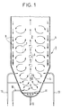
- Figure 1 is a vertical sectional view of a circulating fluidized bed reactor.
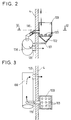
- Figure 2 is a vertical sectional view of a control device according to the invention.
- FIG. 3 is a sectional view along IV-IV of FIG. 2.
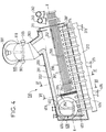
- Figure 4 is a longitudinal sectional view of a cooling device according to the invention.
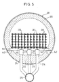
- FIG. 5 is a sectional view along VI-VI of FIG. 4.
- Figure 6 is a sectional view along VII-VII of Figure 4.
- Figure 7 is a vertical sectional view of a circulating fluidized bed reactor equipped with internal beds and devices according to the invention.
- FIG. 8 is a sectional view along VIII-VIII of FIG. 7.
- FIG. 1 which corresponds to a conventional operation of a circulating bed reactor, the latter comprises a lower zone 3 of increasing section upwards and an upper parallelepipedic zone 2.
- the lower zone 3 is provided with a fluidization grid 11, primary air injection means 12 below the grid 11, secondary air injection means 13 above the grid 11 and fuel introduction means 10.
- the walls 5 surrounding this lower zone 3 are provided with heat exchange tubes.
- the upper zone 2 is surrounded by walls 4 provided with heat exchange tubes.
- the solid particles rise above the grid 11 towards the top of the reactor according to the arrows 6. These particles tend to spread towards the walls 4, 5 and fall back down. However, some of the finer particles are re-entrained upwards, according to vortex movements such as 7. The other particles approach the walls 4, 5 and flow along them downwards according to the arrows 8.
- FIGS. 2 and 3 A preferred embodiment of the device for continuously monitoring the internal circulation rate of solid particles according to the invention is shown in FIGS. 2 and 3.
- the cooling device comprises a discharge pipe 201 inclined downward at an angle of 5 to 20 degrees relative to a horizontal plane, of longitudinal axis xx, provided of a refractory lining 202 ensuring thermal insulation and mechanical protection, receiving in the upper part by an inlet sheath 203 of the hot solid particles.
- the inclined pipe 201 is equipped with a fluidization assembly for solid particles 207 and a transverse wall 204 for retaining solid particles.
- a fluidized tank for receiving solid particles between the inlet sheath 203 and the wall 204.
- This wall 204 extends only over a part of the internal section of the pipe 201 and delimits in the upper part a passage 205 for discharging the particles.
- This retaining wall 204 is extractable and made up of elongated superimposed and removable elements as will be specified below with the aid of FIG. 6.
- this receiving tank is arranged a cooling arrangement comprising a set of heat exchange tubes 206 where a heat transfer fluid circulates.
- the set of exchange tubes 206 consists of tubes 261 parallel to the axis x-x arranged upstream of the transverse wall.
- the exchange tubes 261 are concentric double tubes, the inlet 262 and the outlet 263 of the fluid being located on the same side of the pipe 201, namely on the outer side of the highest front wall 211 of the line 201.
- this set of tubes 206 is integral with the highest front wall 211 of line 201.
- a holding device 264 is provided near the end of the tubes 261 close to the retaining wall 204.
- the upper heat exchange tubes 261 are protected by metal shields 212 opposite the inlet sheath 203.
- This set of exchange tubes 206 will be described below in more detail with the aid of FIG. 5.
- the fluidization assembly 207 comprises nozzles 271 passing through the pipe 201 in the lower part of the reception tank thus formed and supplied by a manifold 272 located under the pipe 201. Depending on the length of the reception tank, several collectors 272 can be provided. In these manifolds 272 is injected the fluidizing gas through the inlets 273.
- the set of exchange tubes 206 comprises a certain number of tubes 261 arranged parallel to each other and held by welded fins 265 distributed transversely and longitudinally to form a set of rigid tubes.
- a holding device 264 consisting of a cross member 641 fixed on two brackets 642 welded to the external metal casing of the pipe 201 and supporting cradles 643 in which are placed the lower tubes of the tube assembly 206.
- Each exchange tube 261 consists of two concentric tubes, the internal of which is connected to the heat transfer fluid inlet 262 and the external to the heat transfer fluid outlet 263, these two tubes being in communication at their end close to the transverse wall 204.
- the inlet temperatures t ee t and output to the heat transfer fluid are measured at the entrance 262 and exit 263, the fluid flow e is known.
- fluidization nozzles 271 can be arranged in alignment, these nozzles being connected to the manifold 272 by the gas supply pipes 274. Inside the pipe 201, these fluidization gas supply pipes 274 are embedded in an additional thickness 221 of refractory material.
- the retaining wall 204 is particularly visible in FIG. 6.
- the pipe 201 has a lateral opening delimited by an extension part 213 so that this opening is flat and rectangular. In this opening is introduced the wall 204 which is of the extractable drawer type.
- the external part 241 comprises an external part 241 in the form of a cover which is applied and fixed to the extension part 213 of the pipe 201 for example by screws 242.
- This external part 241 supports the internal part which constitutes the retaining wall in oneself.
- first tubular end pieces 243 aligned over the entire height of the internal volume of the pipe 201.
- tubes 244 constituting elongated superimposed and removable elements.
- These tubes 244 are of such length that they can be at their other end fitted into a rounded piece 245 supporting in correspondence second tubular ends 246 aligned over the entire height of the interior volume of the pipe 201.
- the number of tubes 244 to be installed is determined.
- the operation of the device being stopped and to allow optimal operation of the cooling device the transverse wall 4 is removed, the number of adequate tubes 244 put in place by interlocking and the wall 204 is again fixed to allow the operation of the cooling device.
- the external part 241 comprises channels 247 in which thermocouple wires are arranged allowing the determination of the temperature at several height levels of the retaining wall 204. It includes, to allow this determination, an accessible external connection box 248 as well as gripping means 249 for removing and placing the retaining wall 204.
- tubes 244 and tubular end pieces 243 and 246 were chosen because of their relatively simple and reliable construction and constitution. However, such a transverse wall of adjustable height can be produced with superimposed elements of different shape.
- the first device for measuring the temperature 300 of the solids leaving the tank 100 is visible in FIG. 4.
- the cooling device 200 is disposed upstream of the pipe 201 of the cooling device 200 and comprises three temperature measurement probes 301, 302, 303 passing through the discharge pipe 110. These probes are optionally arranged at different levels and distributed over the periphery of the evacuation pipe 110, offset by 120 ° from one another. They make it possible to determine on average the temperature t es of entry of the solids into the cooling device 200.
- the second device for measuring the temperature of the solids 400 at the outlet of the cooling device 200 is visible in FIG. 4.
- thermocouple wires placed in the tubes 244 and passing through the channels. 247 of the external part 241 of the retaining wall 204.
- These nozzles 403 are arranged as those of the cooling device 200. They pass through the pipe extension 401 in its lower part and are supplied by a manifold 404 located under the pipe extension 401. In this manifold 404, the fluidizing gas is injected through the inlet 405. This fluidization additional makes it possible to homogenize the flow of solid particles in line extension 401.
- another straight probe 406 can be placed at the end of the pipe extension 401.
- the outlet temperature t ss of the solid particles at the outlet of the cooling device 200 can be determined by average.
- the lower zone 3 is provided with a fluidization grid 11 which can be compartmentalized and with primary air injection means 12 below the grid 11. Secondary air injection means 13 above the grid 11 and fuel introduction means 10 are also provided in a conventional manner per se.
- the walls 5 surrounding the lower zone 3 are provided with heat exchange tubes and the upper zone 2 is surrounded by walls 4 provided with heat exchange tubes.
- Figure 8 is a horizontal sectional view of the reactor shown in Figure 7. It comprises several control devices distributed over its inner periphery, these devices being arranged at the same height.
- a control device according to the invention can be installed anywhere in the reactor where it is desired to carry out continuous control of the internal circulation of solid particles.
- such devices 100, 200 are placed on the side walls, each compartmentalization of the fluidization grid.
- the reactor is divided into three 111, 112, 113 as shown in Figure 8, three devices 100, 200 are arranged on the side walls, one at each corner and one in the middle of these walls.
- the longitudinal and transverse distribution of the gas supply to the compartments can be adjusted accordingly.
- control devices are arranged in a horizontal plane above the internal beds 22, 23 or as shown in Figures 7 and 8, at the level of these internal beds.
- control devices arranged on the side walls of the reactor have advantageously their sampling tank 100 formed by a compartment of the corresponding internal bed 22, 23.
Landscapes
- Engineering & Computer Science (AREA)
- Chemical & Material Sciences (AREA)
- Mechanical Engineering (AREA)
- General Engineering & Computer Science (AREA)
- Combustion & Propulsion (AREA)
- Physics & Mathematics (AREA)
- Thermal Sciences (AREA)
- Organic Chemistry (AREA)
- Chemical Kinetics & Catalysis (AREA)
- Devices And Processes Conducted In The Presence Of Fluids And Solid Particles (AREA)
- Basic Packing Technique (AREA)
- Heat-Exchange Devices With Radiators And Conduit Assemblies (AREA)
Applications Claiming Priority (2)
| Application Number | Priority Date | Filing Date | Title |
|---|---|---|---|
| FR9409365A FR2723003B1 (fr) | 1994-07-28 | 1994-07-28 | Procede et dispositif de controle de la circulation interne dans un reacteur a lit fluidise et reacteur equipe d'un tel dispositif |
| FR9409365 | 1994-07-28 |
Publications (2)
| Publication Number | Publication Date |
|---|---|
| EP0694331A1 true EP0694331A1 (de) | 1996-01-31 |
| EP0694331B1 EP0694331B1 (de) | 1998-11-04 |
Family
ID=9465845
Family Applications (1)
| Application Number | Title | Priority Date | Filing Date |
|---|---|---|---|
| EP95401762A Expired - Lifetime EP0694331B1 (de) | 1994-07-28 | 1995-07-25 | Verfahren und Apparat zur Regelung der internen Zirkulation eines Wirbelbettreaktors und mit einem solchen Apparat versehener Reaktor |
Country Status (15)
| Country | Link |
|---|---|
| US (2) | US5628967A (de) |
| EP (1) | EP0694331B1 (de) |
| CN (1) | CN1085107C (de) |
| CA (1) | CA2154834C (de) |
| CZ (1) | CZ187195A3 (de) |
| DE (1) | DE69505747D1 (de) |
| DK (1) | DK0694331T3 (de) |
| ES (1) | ES2125573T3 (de) |
| FI (1) | FI953570L (de) |
| FR (1) | FR2723003B1 (de) |
| PL (1) | PL309811A1 (de) |
| RU (1) | RU2146555C1 (de) |
| SK (1) | SK96095A3 (de) |
| UA (1) | UA26285C2 (de) |
| ZA (1) | ZA956266B (de) |
Families Citing this family (6)
| Publication number | Priority date | Publication date | Assignee | Title |
|---|---|---|---|---|
| ES2220481T3 (es) * | 1999-06-16 | 2004-12-16 | Marine Biotech Incorporated | Reactor de lecho fluidizado y procedimiento para el tratamiento de fluidos. |
| EP2112986B1 (de) | 2007-02-21 | 2020-09-30 | Diversey, Inc. | Ausgabeverschluss |
| US20080276730A1 (en) * | 2007-05-10 | 2008-11-13 | Vector Corporation | Fluid bed sampling device |
| CN104251720B (zh) * | 2014-10-16 | 2016-06-29 | 中国科学院山西煤炭化学研究所 | 气固流化床多相流参数的移动多点测量装置及测量方法 |
| US10717061B1 (en) * | 2019-06-26 | 2020-07-21 | X Energy, Llc | Fluidized bed reactor system allowing particle sampling during an ongoing reaction |
| CN110420479A (zh) * | 2019-07-09 | 2019-11-08 | 长乐佳纶纺织实业有限公司 | 一种涤纶丝生产预结晶用沸腾床 |
Citations (3)
| Publication number | Priority date | Publication date | Assignee | Title |
|---|---|---|---|---|
| DE3006754A1 (de) * | 1979-02-27 | 1980-08-28 | Agency Ind Science Techn | Wirbelschichtreaktor |
| JPH01121616A (ja) * | 1987-11-05 | 1989-05-15 | Sanki Eng Co Ltd | 流動床式焼却炉における循環粒量の制御方法およびその装置 |
| WO1991003316A1 (fr) * | 1989-09-01 | 1991-03-21 | Fina Research S.A. | Procede et appareil de regulation du niveau du lit d'un four a lit fluidise |
Family Cites Families (11)
| Publication number | Priority date | Publication date | Assignee | Title |
|---|---|---|---|---|
| US3802264A (en) * | 1972-07-10 | 1974-04-09 | Geoscience Ltd | Fluid temperature differential flow meter |
| US4167819A (en) * | 1977-12-05 | 1979-09-18 | The United States Of America As Represented By The United States Department Of Energy | Pressure regulator |
| FR2526182B1 (fr) * | 1982-04-28 | 1985-11-29 | Creusot Loire | Procede et dispositif de controle de la temperature d'un lit fluidise |
| US4546012A (en) * | 1984-04-26 | 1985-10-08 | Carbomedics, Inc. | Level control for a fluidized bed |
| DE3433302A1 (de) * | 1984-09-11 | 1986-03-20 | Saarbergwerke AG, 6600 Saarbrücken | Verfahren zur hoehenstandsregelung eines wirbelbettes und schaltungsanordnung zur durchfuehrung des verfahrens |
| DE3721476C1 (de) * | 1987-06-30 | 1988-12-22 | Asea Brown Boveri | Verfahren zum Regeln der Wirbelschichthoehe in einem Pyrolysereaktor sowie Anordnung zur Durchfuehrung des Verfahrens |
| DE3728982C1 (de) * | 1987-08-29 | 1989-02-16 | Asea Brown Boveri | Verfahren zum Regeln der Hoehe eines Wirbelbettes |
| US4865540A (en) * | 1989-02-01 | 1989-09-12 | Foster Wheeler Energy Corporation | Air flow measurement device for fluidized bed reactor |
| DE3910227A1 (de) * | 1989-03-30 | 1990-10-04 | Nymic Anstalt | Reaktormodul |
| US5026171A (en) * | 1989-06-07 | 1991-06-25 | Feller Murray F | Apparatus for flow rate and energy transfer measurements |
| FR2690512B1 (fr) * | 1992-04-27 | 1994-09-09 | Stein Industrie | Réacteur à lit fluidisé circulant comportant des échangeurs extérieurs alimentés par la recirculation interne. |
-
1994
- 1994-07-28 FR FR9409365A patent/FR2723003B1/fr not_active Expired - Fee Related
-
1995
- 1995-07-11 US US08/499,912 patent/US5628967A/en not_active Expired - Fee Related
- 1995-07-19 CZ CZ951871A patent/CZ187195A3/cs unknown
- 1995-07-25 DK DK95401762T patent/DK0694331T3/da active
- 1995-07-25 EP EP95401762A patent/EP0694331B1/de not_active Expired - Lifetime
- 1995-07-25 ES ES95401762T patent/ES2125573T3/es not_active Expired - Lifetime
- 1995-07-25 DE DE69505747T patent/DE69505747D1/de not_active Expired - Lifetime
- 1995-07-26 CN CN95109619A patent/CN1085107C/zh not_active Expired - Fee Related
- 1995-07-26 FI FI953570A patent/FI953570L/fi unknown
- 1995-07-27 ZA ZA956266A patent/ZA956266B/xx unknown
- 1995-07-27 RU RU95113178A patent/RU2146555C1/ru active
- 1995-07-27 UA UA95073540A patent/UA26285C2/uk unknown
- 1995-07-27 PL PL95309811A patent/PL309811A1/xx unknown
- 1995-07-27 CA CA002154834A patent/CA2154834C/fr not_active Expired - Fee Related
- 1995-07-28 SK SK960-95A patent/SK96095A3/sk unknown
-
1996
- 1996-10-09 US US08/731,005 patent/US5700431A/en not_active Expired - Fee Related
Patent Citations (3)
| Publication number | Priority date | Publication date | Assignee | Title |
|---|---|---|---|---|
| DE3006754A1 (de) * | 1979-02-27 | 1980-08-28 | Agency Ind Science Techn | Wirbelschichtreaktor |
| JPH01121616A (ja) * | 1987-11-05 | 1989-05-15 | Sanki Eng Co Ltd | 流動床式焼却炉における循環粒量の制御方法およびその装置 |
| WO1991003316A1 (fr) * | 1989-09-01 | 1991-03-21 | Fina Research S.A. | Procede et appareil de regulation du niveau du lit d'un four a lit fluidise |
Non-Patent Citations (1)
| Title |
|---|
| PATENT ABSTRACTS OF JAPAN vol. 13, no. 365 (M - 859) 15 August 1989 (1989-08-15) * |
Also Published As
| Publication number | Publication date |
|---|---|
| DE69505747D1 (de) | 1998-12-10 |
| ZA956266B (en) | 1996-03-13 |
| US5700431A (en) | 1997-12-23 |
| SK96095A3 (en) | 1996-07-03 |
| FR2723003B1 (fr) | 1996-09-13 |
| ES2125573T3 (es) | 1999-03-01 |
| FI953570A7 (fi) | 1996-01-29 |
| US5628967A (en) | 1997-05-13 |
| CZ187195A3 (en) | 1996-09-11 |
| CA2154834C (fr) | 2000-02-01 |
| CN1126635A (zh) | 1996-07-17 |
| CN1085107C (zh) | 2002-05-22 |
| PL309811A1 (en) | 1996-02-05 |
| FI953570A0 (fi) | 1995-07-26 |
| DK0694331T3 (da) | 1999-07-19 |
| FR2723003A1 (fr) | 1996-02-02 |
| CA2154834A1 (fr) | 1996-01-29 |
| RU2146555C1 (ru) | 2000-03-20 |
| UA26285C2 (uk) | 1999-07-19 |
| EP0694331B1 (de) | 1998-11-04 |
| FI953570L (fi) | 1996-01-29 |
Similar Documents
| Publication | Publication Date | Title |
|---|---|---|
| EP0445599B1 (de) | Sonde für Gasprobeentnahme und thermische Messungen in einem Schachtofen | |
| EP0694331B1 (de) | Verfahren und Apparat zur Regelung der internen Zirkulation eines Wirbelbettreaktors und mit einem solchen Apparat versehener Reaktor | |
| FR2462002A1 (fr) | Reacteur nucleaire refroidi par un metal liquide et muni d'un systeme d'evacuation de la puissance residuelle | |
| CA2114196C (fr) | Four a vapeur a chauffage direct au gaz | |
| FR2513146A1 (fr) | Dispositif d'abaissement de temperature et d'epuration d'un gaz au cours d'un processus de traitement | |
| WO2014009531A1 (fr) | Installation de thermoretraction comportant des moyens de regulation de la temperature a l'interieur de l'enceinte de l'installation | |
| EP2872404B1 (de) | Wärmeschrumpfanlage mit einer wärmedispersionsvorrichtung als einheitliche anordnung | |
| EP0694749B1 (de) | Feststoffpartikel-Kühlungseinrichtung am Ausgang einer Verarbeitungsanordnung | |
| EP0142388B1 (de) | Unter hohem Druck und in Wirbelschicht betriebener Kohlevergaser | |
| FR2561542A1 (fr) | Appareil pour systemes de reaction a lit fluidise | |
| EP0064921B1 (de) | Kühlvorrichtung des Hauptbehälters eines Kernreaktors mit schnellen Neutronen | |
| EP0018262A1 (de) | Schneller Kernreaktor mit einem zylindrischen Innenbehälter | |
| FR2787045A1 (fr) | Piece refractaire d'injection de gaz dans un circuit de coulee de metal liquide | |
| EP0171340A1 (de) | Kondensationsheisswassererzeuger | |
| EP0098770B1 (de) | Rieselkühlturm mit Rinnen | |
| EP1310754B1 (de) | Ofen mit ringförmigen Boden | |
| FR2522114A1 (fr) | Chaudiere a bois ou autres materiaux combustibles solides | |
| FR2721430A1 (fr) | Dispositif et procédé de stockage à sac de matériaux dégageant de la chaleur. | |
| EP0581663A1 (de) | Wärmetauscher mit ringförmig angeordneten Wasserrohren, insbesondere für Brennwertkessel | |
| EP0036347B1 (de) | Zwischenwärmeaustauscher für Nuklear-Reaktor mit schnellen Neutronen | |
| CA2010831A1 (fr) | Regulateur non mecanique du debit de solides etabli entre deux milieux fluidises | |
| FR2513259A1 (fr) | Reacteur de gazeification de matieres carbonees solides | |
| FR2643189A1 (fr) | Dispositif de protection thermique de la virole superieure de supportage d'une cuve suspendue, notamment dans un reacteur nucleaire a neutrons rapides | |
| EP2872405B1 (de) | Wärmeschrumpfanlage mit einer heizkammer mit einem boden und einer glocke | |
| FR2681420A1 (fr) | Dispositif de boite a eau et de vase d'expansion pour echangeur de chaleur a faisceau de tubes verticaux, et echangeur de chaleur comportant un tel dispositif. |
Legal Events
| Date | Code | Title | Description |
|---|---|---|---|
| PUAI | Public reference made under article 153(3) epc to a published international application that has entered the european phase |
Free format text: ORIGINAL CODE: 0009012 |
|
| AK | Designated contracting states |
Kind code of ref document: A1 Designated state(s): BE DE DK ES GB SE |
|
| 17P | Request for examination filed |
Effective date: 19960615 |
|
| 17Q | First examination report despatched |
Effective date: 19970602 |
|
| GRAG | Despatch of communication of intention to grant |
Free format text: ORIGINAL CODE: EPIDOS AGRA |
|
| GRAG | Despatch of communication of intention to grant |
Free format text: ORIGINAL CODE: EPIDOS AGRA |
|
| GRAH | Despatch of communication of intention to grant a patent |
Free format text: ORIGINAL CODE: EPIDOS IGRA |
|
| GRAH | Despatch of communication of intention to grant a patent |
Free format text: ORIGINAL CODE: EPIDOS IGRA |
|
| GRAA | (expected) grant |
Free format text: ORIGINAL CODE: 0009210 |
|
| AK | Designated contracting states |
Kind code of ref document: B1 Designated state(s): BE DE DK ES GB SE |
|
| REF | Corresponds to: |
Ref document number: 69505747 Country of ref document: DE Date of ref document: 19981210 |
|
| PG25 | Lapsed in a contracting state [announced via postgrant information from national office to epo] |
Ref country code: DE Free format text: LAPSE BECAUSE OF FAILURE TO SUBMIT A TRANSLATION OF THE DESCRIPTION OR TO PAY THE FEE WITHIN THE PRESCRIBED TIME-LIMIT Effective date: 19990205 |
|
| REG | Reference to a national code |
Ref country code: ES Ref legal event code: FG2A Ref document number: 2125573 Country of ref document: ES Kind code of ref document: T3 |
|
| GBT | Gb: translation of ep patent filed (gb section 77(6)(a)/1977) |
Effective date: 19990301 |
|
| RAP2 | Party data changed (patent owner data changed or rights of a patent transferred) |
Owner name: ALSTOM ENERGY SYSTEMS S.A. |
|
| REG | Reference to a national code |
Ref country code: DK Ref legal event code: T3 |
|
| PLBE | No opposition filed within time limit |
Free format text: ORIGINAL CODE: 0009261 |
|
| STAA | Information on the status of an ep patent application or granted ep patent |
Free format text: STATUS: NO OPPOSITION FILED WITHIN TIME LIMIT |
|
| 26N | No opposition filed | ||
| PGFP | Annual fee paid to national office [announced via postgrant information from national office to epo] |
Ref country code: GB Payment date: 20010614 Year of fee payment: 7 |
|
| PGFP | Annual fee paid to national office [announced via postgrant information from national office to epo] |
Ref country code: SE Payment date: 20010702 Year of fee payment: 7 Ref country code: DK Payment date: 20010702 Year of fee payment: 7 |
|
| PGFP | Annual fee paid to national office [announced via postgrant information from national office to epo] |
Ref country code: BE Payment date: 20010713 Year of fee payment: 7 |
|
| PGFP | Annual fee paid to national office [announced via postgrant information from national office to epo] |
Ref country code: ES Payment date: 20010716 Year of fee payment: 7 |
|
| REG | Reference to a national code |
Ref country code: GB Ref legal event code: IF02 |
|
| PG25 | Lapsed in a contracting state [announced via postgrant information from national office to epo] |
Ref country code: GB Free format text: LAPSE BECAUSE OF NON-PAYMENT OF DUE FEES Effective date: 20020725 |
|
| PG25 | Lapsed in a contracting state [announced via postgrant information from national office to epo] |
Ref country code: SE Free format text: LAPSE BECAUSE OF NON-PAYMENT OF DUE FEES Effective date: 20020726 Ref country code: ES Free format text: LAPSE BECAUSE OF NON-PAYMENT OF DUE FEES Effective date: 20020726 |
|
| PG25 | Lapsed in a contracting state [announced via postgrant information from national office to epo] |
Ref country code: DK Free format text: LAPSE BECAUSE OF NON-PAYMENT OF DUE FEES Effective date: 20020731 Ref country code: BE Free format text: LAPSE BECAUSE OF NON-PAYMENT OF DUE FEES Effective date: 20020731 |
|
| BERE | Be: lapsed |
Owner name: *GEC ALSTHOM STEIN INDUSTRIE Effective date: 20020731 |
|
| REG | Reference to a national code |
Ref country code: DK Ref legal event code: EBP |
|
| EUG | Se: european patent has lapsed | ||
| GBPC | Gb: european patent ceased through non-payment of renewal fee |
Effective date: 20020725 |
|
| REG | Reference to a national code |
Ref country code: ES Ref legal event code: FD2A Effective date: 20030811 |