EP0694676B1 - Installation pour puits pétrolier - Google Patents
Installation pour puits pétrolier Download PDFInfo
- Publication number
- EP0694676B1 EP0694676B1 EP95401776A EP95401776A EP0694676B1 EP 0694676 B1 EP0694676 B1 EP 0694676B1 EP 95401776 A EP95401776 A EP 95401776A EP 95401776 A EP95401776 A EP 95401776A EP 0694676 B1 EP0694676 B1 EP 0694676B1
- Authority
- EP
- European Patent Office
- Prior art keywords
- well
- installation
- casing
- pipe
- hydrocarbons
- Prior art date
- Legal status (The legal status is an assumption and is not a legal conclusion. Google has not performed a legal analysis and makes no representation as to the accuracy of the status listed.)
- Expired - Lifetime
Links
- 238000009434 installation Methods 0.000 title claims description 18
- 239000003129 oil well Substances 0.000 title claims description 11
- 229930195733 hydrocarbon Natural products 0.000 claims description 21
- 150000002430 hydrocarbons Chemical class 0.000 claims description 21
- 239000011435 rock Substances 0.000 claims description 15
- 239000000463 material Substances 0.000 claims 2
- 239000012212 insulator Substances 0.000 claims 1
- 238000004519 manufacturing process Methods 0.000 description 7
- 239000003208 petroleum Substances 0.000 description 5
- 230000004913 activation Effects 0.000 description 3
- 239000007788 liquid Substances 0.000 description 3
- 238000005086 pumping Methods 0.000 description 3
- 238000002347 injection Methods 0.000 description 2
- 239000007924 injection Substances 0.000 description 2
- 238000000034 method Methods 0.000 description 2
- 239000004215 Carbon black (E152) Substances 0.000 description 1
- 238000001816 cooling Methods 0.000 description 1
- 230000006866 deterioration Effects 0.000 description 1
- 230000008030 elimination Effects 0.000 description 1
- 238000003379 elimination reaction Methods 0.000 description 1
- 238000005259 measurement Methods 0.000 description 1
- 239000002184 metal Substances 0.000 description 1
- 230000009972 noncorrosive effect Effects 0.000 description 1
- 230000035699 permeability Effects 0.000 description 1
- 230000001737 promoting effect Effects 0.000 description 1
- 230000001012 protector Effects 0.000 description 1
- 230000035939 shock Effects 0.000 description 1
- 238000011144 upstream manufacturing Methods 0.000 description 1
- XLYOFNOQVPJJNP-UHFFFAOYSA-N water Substances O XLYOFNOQVPJJNP-UHFFFAOYSA-N 0.000 description 1
Images
Classifications
-
- E—FIXED CONSTRUCTIONS
- E21—EARTH OR ROCK DRILLING; MINING
- E21B—EARTH OR ROCK DRILLING; OBTAINING OIL, GAS, WATER, SOLUBLE OR MELTABLE MATERIALS OR A SLURRY OF MINERALS FROM WELLS
- E21B43/00—Methods or apparatus for obtaining oil, gas, water, soluble or meltable materials or a slurry of minerals from wells
- E21B43/12—Methods or apparatus for controlling the flow of the obtained fluid to or in wells
-
- E—FIXED CONSTRUCTIONS
- E21—EARTH OR ROCK DRILLING; MINING
- E21B—EARTH OR ROCK DRILLING; OBTAINING OIL, GAS, WATER, SOLUBLE OR MELTABLE MATERIALS OR A SLURRY OF MINERALS FROM WELLS
- E21B43/00—Methods or apparatus for obtaining oil, gas, water, soluble or meltable materials or a slurry of minerals from wells
Definitions
- the present invention relates to an installation for an oil well and more particularly, but not exclusively, to an installation for an oil well activated, well in which the flow of hydrocarbons from bottom to the surface is assisted, temporarily or continuously by an activation means, for example a pump whose output is arranged at the bottom of the well.
- an activation means for example a pump whose output is arranged at the bottom of the well.
- the natural flow hydrocarbons from the bottom to the surface is insufficient for allow or maintain commercial production. This is due either at the high viscosity of the hydrocarbons, or at a too low natural pressure at the bottom of the well or even at a combination of the two.
- a system assistance or well activation system we can have a pump at the lower end of a tube production located in the well. This pump, fitted with a motor electric submerged at the bottom of the well and supplied by a cable arranged in the annular space between the casing and the casing from the well, sends hydrocarbons under pressure from the bottom to the area.
- the subject of the present invention is an installation for oil wells offering increased control flexibility of the flow of hydrocarbons and which makes it possible to define, in the well, a chamber isolated from hydrocarbons in from the bottom of the well.
- the invention proposes a installation for an oil well extending from the surface to a layer of petroleum rock, comprising a first casing disposed in the well and forming a flow path to the surface for hydrocarbons from the rock layer oil a second casing placed in the well and forming a second flow path to the surface for hydrocarbons from the same layer of rock, the installation further comprising a chamber between the casings and the wall of the well, which does not contain hydrocarbons in origin of the rock layer characterized in that the casings communicate with each other at a point on the surface or at the interior of the well by a conduit which opens into the second casing inside a venturi arranged in the second casing.
- the second casing is fitted with an electric pump, the cable of which feed largely extends into the room.
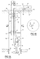
- an oil well 10 extends between surface 12 and a layer of petroleum rock 14.
- the well is provided with perforations 16 opening into the petroleum rock that allows the flow of hydrocarbons towards the inside of the well 10.
- the well 10 has a casing 18 which makes the well tight compared to the layers of rocks crossed by the well.
- the casings 20 and 22 extend from parallel, but the casings can be arranged concentrically, one inside the other.
- the first casing 20 which extends between a wellhead, shown schematically at 24, and a joint 26, more commonly called “packer", arranged, for example, about 100 m above the level of the oil rock 14.
- the first casing 20 is possibly fitted with a safety valve 28 to its upper end, for example 50 m from the ground.
- the diameter of the second casing 22 is preferably less than that of the first casing 20.
- the second casing 22 includes a pumping assembly, generally represented at 30, which includes a pump 32 rotated by a motor electric 34.
- the electric motor 34 is powered by a electric cable 36 disposed outside the casings 20, 22.
- the cable 36 extends in the vicinity of the two casings 20, 22, as shown in FIG. 1B, sheltered thus mechanical shocks which can occur during well repair operations.
- the electric motor is surrounded by a jacket 38 provided with a tubular extension 40 which extends to a level below the perforations 16.
- the function of the pump is to suck up the most heavy, the lightest tending to rise naturally by the casing 20.
- the two casings 20 and 22 are joined by seals 46.
- a first fraction of hydrocarbons passes through the first casing 20 which, having a large diameter, promotes the natural flow of hydrocarbons with minimum friction.
- the heaviest hydrocarbons from petroleum rock follow a path represented by arrows 42 towards the tubular part 40, which communicates with inlets 44 of pump 32.
- This path has a flow section descendant which promotes the gravitational elimination of free gas, present in the liquid, by difference in phase density.
- the passage of liquid hydrocarbons around the front 34 engine reaching the pump 32 ensures the cooling of the motor.
- conduits 20 'and 22' are connected by a conduit 48 which opens into a venturi 50 arranged in the conduit 22 'and whose function is to reinforce the suction of light hydrocarbons in line 22 '.
- the conduit 48 is provided with a non-return valve 52.
- the venturi 50 is adjustable.
- This assembly can also be installed in the well, before the fork, to a depth determined based on optimal hydraulic conditions and especially under seal 26 if you want to save a head double well and casing in the upper part. In this case, this assembly can be implemented or replaced by a light intervention, for example using a cable.
- the flow of the second fraction in the conduit 22 ' through the venturi 50 creates a depression which reinforces the suction of the first fraction flowing in the conduit 20 '. For this reason on the one hand, and because it reduces the pressure at the bottom of the well, pumping, or other method flow of the second fraction in the conduit 22 ', serves to increase the flow capacity of the first fraction in the conduit 20 '.
- the volume at the outside of the casings 20, 22 in the casing 18 between the seal 26 and the well head 24 constitutes a chamber 51 which is filled with a chemically inert product which, in a fashion of preferred embodiment, is a good thermal insulating gel, intended to reduce thermal convection in chamber 51.
- a chemically inert product which, in a fashion of preferred embodiment, is a good thermal insulating gel, intended to reduce thermal convection in chamber 51.
- the casings 20 and 22 are connected to each other by upstream of safety valves 28,29 at one or more points by hydraulic conduits, represented schematically in 54, provided with a control valve (not shown) which can be interchanged with the cable from the surface.
- hydraulic conduits represented schematically in 54, provided with a control valve (not shown) which can be interchanged with the cable from the surface.
- Installation in the well 10 of the two casings 20 and 22 also offers the possibility of assisting the flow of hydrocarbons by gas injection to the bottom of the well so to lighten the hydrocarbon column.
- this gas injection more commonly called “gas-lift”
- this gas injection is carried out by the casing 22 of smaller diameter in order to drain the hydrocarbons through the casing 20 of diameter most important. It is also possible to inject gas from the casing 20 to casing 22 in order to relieve the pump by operation.
- the installation according to the invention allows numerous one-off operations simultaneously with pumping, by accessing the bottom of the well using devices hung on the cable such as background parameter measurements, for example, flow, temperature or pressures.
- the installation also makes it possible to make perforations while depressurizing the bottom of the well with the pump, which has the advantage of promoting the removal of debris of shots and therefore improve the permeability of the holes as well performed in the casing.
- the perforation barrel is lowered to the cable by the second casing.
Landscapes
- Life Sciences & Earth Sciences (AREA)
- Engineering & Computer Science (AREA)
- Geology (AREA)
- Mining & Mineral Resources (AREA)
- Physics & Mathematics (AREA)
- Environmental & Geological Engineering (AREA)
- Fluid Mechanics (AREA)
- General Life Sciences & Earth Sciences (AREA)
- Geochemistry & Mineralogy (AREA)
- Structures Of Non-Positive Displacement Pumps (AREA)
- Jet Pumps And Other Pumps (AREA)
- Production Of Liquid Hydrocarbon Mixture For Refining Petroleum (AREA)
Description
- la figure 1A est une vue schématique en coupe d'un puits pétrolier activé selon l'invention ; et
- la figure 1B est une section prise selon la ligne 1B-1B de la figure 1A.
Claims (4)
- Installation pour puits pétrolier (10) s'étendant de la surface (12) vers une couche de roche pétrolifère (14), comprenant un premier tubage (20) disposé dans le puits et formant une voie d'écoulement vers la surface pour les hydrocarbures provenant de la couche de roche pétrolifère (14) un second tubage (22) disposé dans le puits et formant une seconde voie d'écoulement vers la surface pour les hydrocarbures provenant de la même couche de roche, l'installation comprenant de plus une chambre (51) entre les tubages (20,22) et la paroi (18) du puits, qui ne contient pas d'hydrocarbures en provenance de la couche de roche caractérisée en ce que les tubages communiquent entre eux en un point (48) à la surface (12) ou à l'intérieur du puits par un conduit (48) qui débouche dans le second tubage (22) à l'intérieur d'un venturi (50) disposé dans le second tubage.
- Installation selon la revendication 1 caractérisée en ce que le second tubage (22) est muni d'une pompe électrique (32,34) dont le câble d'alimentation en grande partie s'étend dans la chambre (51).
- Installation selon la revendication 1 ou 2, caractérisée en ce que la chambre (51) est emplie d'un produit inerte.
- Installation selon la revendication 3 caractérisée en ce que le produit inerte est un gel bon isolant thermique.
Applications Claiming Priority (2)
| Application Number | Priority Date | Filing Date | Title |
|---|---|---|---|
| FR9409455A FR2723143B1 (fr) | 1994-07-29 | 1994-07-29 | Installation pour puits petrolier |
| FR9409455 | 1994-07-29 |
Publications (2)
| Publication Number | Publication Date |
|---|---|
| EP0694676A1 EP0694676A1 (fr) | 1996-01-31 |
| EP0694676B1 true EP0694676B1 (fr) | 1998-06-03 |
Family
ID=9465909
Family Applications (1)
| Application Number | Title | Priority Date | Filing Date |
|---|---|---|---|
| EP95401776A Expired - Lifetime EP0694676B1 (fr) | 1994-07-29 | 1995-07-27 | Installation pour puits pétrolier |
Country Status (6)
| Country | Link |
|---|---|
| US (1) | US5657821A (fr) |
| EP (1) | EP0694676B1 (fr) |
| CA (1) | CA2154994C (fr) |
| FR (1) | FR2723143B1 (fr) |
| NO (1) | NO308867B1 (fr) |
| OA (1) | OA10174A (fr) |
Families Citing this family (11)
| Publication number | Priority date | Publication date | Assignee | Title |
|---|---|---|---|---|
| FR2759113B1 (fr) * | 1997-01-31 | 1999-03-19 | Elf Aquitaine | Installation de pompage d'un effluent biphasique liquide/gaz |
| FR2761110B1 (fr) * | 1997-03-18 | 1999-05-28 | Elf Aquitaine | Installation pour puits de production d'effluent |
| US6092599A (en) * | 1997-08-22 | 2000-07-25 | Texaco Inc. | Downhole oil and water separation system and method |
| US6079491A (en) * | 1997-08-22 | 2000-06-27 | Texaco Inc. | Dual injection and lifting system using a rod driven progressive cavity pump and an electrical submersible progressive cavity pump |
| US6135210A (en) * | 1998-07-16 | 2000-10-24 | Camco International, Inc. | Well completion system employing multiple fluid flow paths |
| US6260626B1 (en) | 1999-02-24 | 2001-07-17 | Camco International, Inc. | Method and apparatus for completing an oil and gas well |
| US6817409B2 (en) | 2001-06-13 | 2004-11-16 | Weatherford/Lamb, Inc. | Double-acting reciprocating downhole pump |
| US6926504B2 (en) * | 2001-06-26 | 2005-08-09 | Total Fiza Elf | Submersible electric pump |
| US7673676B2 (en) * | 2007-04-04 | 2010-03-09 | Schlumberger Technology Corporation | Electric submersible pumping system with gas vent |
| US8950476B2 (en) * | 2011-03-04 | 2015-02-10 | Accessesp Uk Limited | Coiled tubing deployed ESP |
| US12378857B1 (en) * | 2024-05-09 | 2025-08-05 | Saudi Arabian Oil Company | Systems and methods for multiphase formation fluid production utilizing an electric submersible pump |
Family Cites Families (16)
| Publication number | Priority date | Publication date | Assignee | Title |
|---|---|---|---|---|
| US1431779A (en) * | 1920-11-15 | 1922-10-10 | Conrader Rudolph | Method of treating oil wells and apparatus therefor |
| US2227538A (en) * | 1939-05-08 | 1941-01-07 | Harvey T Dorton | Apparatus for flowing wells |
| US2580332A (en) * | 1946-11-22 | 1951-12-25 | Don H Teetor | Pumping apparatus |
| US2850099A (en) * | 1953-04-13 | 1958-09-02 | Cicero C Brown | Well production apparatus |
| US3399623A (en) * | 1966-07-14 | 1968-09-03 | James R. Creed | Apparatus for and method of producing viscid oil |
| US3746089A (en) * | 1971-07-19 | 1973-07-17 | Dresser Ind | Apparatus for producing multiple zone oil and gas wells |
| US3765483A (en) * | 1971-08-09 | 1973-10-16 | Dresser Ind | Method and apparatus for producing dual zone oil and gas wells |
| US3980138A (en) * | 1974-11-15 | 1976-09-14 | Knopik Duane L | Underground fluid recovery device |
| US4266607A (en) * | 1980-04-07 | 1981-05-12 | Mobil Oil Corporation | Method for protecting a carbon dioxide production well from corrosion |
| US4296814A (en) * | 1980-07-18 | 1981-10-27 | Conoco Inc. | Method for thermally insulating wellbores |
| US4345647A (en) * | 1980-07-18 | 1982-08-24 | Carmichael William C | Apparatus to increase oil well flow |
| US4390061A (en) * | 1980-12-31 | 1983-06-28 | Charles Short | Apparatus for production of liquid from wells |
| US4832127A (en) * | 1987-12-29 | 1989-05-23 | Shell Western E&P Inc. | Method and apparatus for producing viscous crudes |
| US4878539A (en) * | 1988-08-02 | 1989-11-07 | Anders Energy Corporation | Method and system for maintaining and producing horizontal well bores |
| US5289881A (en) * | 1991-04-01 | 1994-03-01 | Schuh Frank J | Horizontal well completion |
| US5450901A (en) * | 1993-12-17 | 1995-09-19 | Marathon Oil Company | Apparatus and process for producing and reinjecting gas |
-
1994
- 1994-07-29 FR FR9409455A patent/FR2723143B1/fr not_active Expired - Lifetime
-
1995
- 1995-07-27 EP EP95401776A patent/EP0694676B1/fr not_active Expired - Lifetime
- 1995-07-28 OA OA60694A patent/OA10174A/fr unknown
- 1995-07-28 CA CA002154994A patent/CA2154994C/fr not_active Expired - Lifetime
- 1995-07-28 NO NO953000A patent/NO308867B1/no not_active IP Right Cessation
- 1995-07-31 US US08/509,572 patent/US5657821A/en not_active Expired - Lifetime
Also Published As
| Publication number | Publication date |
|---|---|
| US5657821A (en) | 1997-08-19 |
| NO953000D0 (no) | 1995-07-28 |
| NO308867B1 (no) | 2000-11-06 |
| EP0694676A1 (fr) | 1996-01-31 |
| FR2723143B1 (fr) | 1996-09-27 |
| NO953000L (no) | 1996-01-30 |
| OA10174A (fr) | 1996-12-18 |
| CA2154994C (fr) | 2005-04-12 |
| CA2154994A1 (fr) | 1996-01-30 |
| FR2723143A1 (fr) | 1996-02-02 |
Similar Documents
| Publication | Publication Date | Title |
|---|---|---|
| EP1656517B1 (fr) | Methode d'evacuation des gaz de permeation d'une conduite tubulaire flexible et conduite adaptee a sa mise en oeuvre | |
| EP0097080B1 (fr) | Système de production des gisements sous-marins de fluides | |
| CA2209515C (fr) | Procede et installation de pompage d'un effluent petrolier | |
| CA2154994C (fr) | Installation pour puits petrolier | |
| EP0096636B1 (fr) | Système d'exploitation des fluides d'un gisement | |
| EP0457879B1 (fr) | Dispositif et procede de nettoyage d'un puits souterrain | |
| EP0013854A1 (fr) | Procédé et dispositif de sécurité pour stockage souterrain d'un fluide sous pression | |
| FR2621071A1 (fr) | Methode et systeme de production d'un effluent contenu dans une formation geologique sous-marine | |
| FR2934635A1 (fr) | Installation de conduite montante flexible de transport d'hydrocarbures pour grande profondeur | |
| FR2672934A1 (fr) | Systeme de liberation de lanceurs pour tete de cimentation ou outil de fond sous-marin, pour puits petroliers. | |
| CA2251611C (fr) | Installation de pompage d'un effluent biphasique liquide/gaz | |
| EP3140492B1 (fr) | Ensemble de jonction pour former une conduite | |
| FR2652610A1 (fr) | Procede de pompage de melange liquide gaz dans un puits d'extraction petrolier et dispositif de mise en óoeuvre du procede. | |
| FR2809136A1 (fr) | Installation de liaison fond-surface pour conduite sous- marine, dispositif de liaison entre un flotteur et un riser, et procede d'intervention dans ledit riser | |
| FR2727475A1 (fr) | Methode et systeme de pompage comportant une pompe volumetrique entrainee par un tube continu - application aux puits devies | |
| EP0489137B1 (fr) | Tube de production avec ligne hydraulique integree | |
| FR2488972A1 (fr) | Procede d'intervention sur une conduite transportant un fluide notamment sur une conduite immergee | |
| EP1509671B1 (fr) | Colonne montante du type multi-catenaire | |
| FR2758852A1 (fr) | Procede de pompage d'un fluide | |
| FR3017898A1 (fr) | Tete et procede d'aspiration de liquide dans un forage et/ou une cavite souterraine | |
| FR2880910A1 (fr) | Dispositif de remontee de produits petroliers a partir de puits de production en mer | |
| FR2925933A1 (fr) | Systeme de recuperation assistee de petroles extra-lourds | |
| FR2687187A1 (fr) | Obturateur de puits de forage. | |
| FR2491107A1 (fr) | Procede et dispositif de fabrication d'un corps de fondation en beton dans le sol | |
| FR2633662A1 (fr) | Systeme et procede de production d'effluents a partir d'un puits fore dans le sol marin |
Legal Events
| Date | Code | Title | Description |
|---|---|---|---|
| PUAI | Public reference made under article 153(3) epc to a published international application that has entered the european phase |
Free format text: ORIGINAL CODE: 0009012 |
|
| 17P | Request for examination filed |
Effective date: 19950731 |
|
| AK | Designated contracting states |
Kind code of ref document: A1 Designated state(s): FR GB IT NL |
|
| 17Q | First examination report despatched |
Effective date: 19961009 |
|
| GRAG | Despatch of communication of intention to grant |
Free format text: ORIGINAL CODE: EPIDOS AGRA |
|
| GRAG | Despatch of communication of intention to grant |
Free format text: ORIGINAL CODE: EPIDOS AGRA |
|
| GRAH | Despatch of communication of intention to grant a patent |
Free format text: ORIGINAL CODE: EPIDOS IGRA |
|
| GRAH | Despatch of communication of intention to grant a patent |
Free format text: ORIGINAL CODE: EPIDOS IGRA |
|
| GRAA | (expected) grant |
Free format text: ORIGINAL CODE: 0009210 |
|
| AK | Designated contracting states |
Kind code of ref document: B1 Designated state(s): FR GB IT NL |
|
| ITF | It: translation for a ep patent filed | ||
| GBT | Gb: translation of ep patent filed (gb section 77(6)(a)/1977) |
Effective date: 19980902 |
|
| PLBE | No opposition filed within time limit |
Free format text: ORIGINAL CODE: 0009261 |
|
| STAA | Information on the status of an ep patent application or granted ep patent |
Free format text: STATUS: NO OPPOSITION FILED WITHIN TIME LIMIT |
|
| 26N | No opposition filed | ||
| REG | Reference to a national code |
Ref country code: GB Ref legal event code: IF02 |
|
| PGFP | Annual fee paid to national office [announced via postgrant information from national office to epo] |
Ref country code: GB Payment date: 20140624 Year of fee payment: 20 |
|
| PGFP | Annual fee paid to national office [announced via postgrant information from national office to epo] |
Ref country code: IT Payment date: 20140624 Year of fee payment: 20 |
|
| PGFP | Annual fee paid to national office [announced via postgrant information from national office to epo] |
Ref country code: NL Payment date: 20140619 Year of fee payment: 20 |
|
| PGFP | Annual fee paid to national office [announced via postgrant information from national office to epo] |
Ref country code: FR Payment date: 20140721 Year of fee payment: 20 |
|
| REG | Reference to a national code |
Ref country code: GB Ref legal event code: PE20 Expiry date: 20150726 |
|
| PG25 | Lapsed in a contracting state [announced via postgrant information from national office to epo] |
Ref country code: GB Free format text: LAPSE BECAUSE OF EXPIRATION OF PROTECTION Effective date: 20150726 |