EP0694831A2 - Mit einer Kompressionsfunktion versehenes Rechnersystem mit einer Speichereinheit und Verwaltungsverfahren eines Speicherbereichs dafür - Google Patents
Mit einer Kompressionsfunktion versehenes Rechnersystem mit einer Speichereinheit und Verwaltungsverfahren eines Speicherbereichs dafür Download PDFInfo
- Publication number
- EP0694831A2 EP0694831A2 EP95111704A EP95111704A EP0694831A2 EP 0694831 A2 EP0694831 A2 EP 0694831A2 EP 95111704 A EP95111704 A EP 95111704A EP 95111704 A EP95111704 A EP 95111704A EP 0694831 A2 EP0694831 A2 EP 0694831A2
- Authority
- EP
- European Patent Office
- Prior art keywords
- data
- host computer
- file
- physical
- physical blocks
- Prior art date
- Legal status (The legal status is an assumption and is not a legal conclusion. Google has not performed a legal analysis and makes no representation as to the accuracy of the status listed.)
- Withdrawn
Links
Images


Classifications
-
- G—PHYSICS
- G06—COMPUTING OR CALCULATING; COUNTING
- G06F—ELECTRIC DIGITAL DATA PROCESSING
- G06F3/00—Input arrangements for transferring data to be processed into a form capable of being handled by the computer; Output arrangements for transferring data from processing unit to output unit, e.g. interface arrangements
- G06F3/06—Digital input from, or digital output to, record carriers, e.g. RAID, emulated record carriers or networked record carriers
- G06F3/0601—Interfaces specially adapted for storage systems
- G06F3/0602—Interfaces specially adapted for storage systems specifically adapted to achieve a particular effect
- G06F3/0608—Saving storage space on storage systems
-
- G—PHYSICS
- G06—COMPUTING OR CALCULATING; COUNTING
- G06F—ELECTRIC DIGITAL DATA PROCESSING
- G06F3/00—Input arrangements for transferring data to be processed into a form capable of being handled by the computer; Output arrangements for transferring data from processing unit to output unit, e.g. interface arrangements
- G06F3/06—Digital input from, or digital output to, record carriers, e.g. RAID, emulated record carriers or networked record carriers
- G06F3/0601—Interfaces specially adapted for storage systems
- G06F3/0628—Interfaces specially adapted for storage systems making use of a particular technique
- G06F3/0629—Configuration or reconfiguration of storage systems
- G06F3/0631—Configuration or reconfiguration of storage systems by allocating resources to storage systems
-
- G—PHYSICS
- G06—COMPUTING OR CALCULATING; COUNTING
- G06F—ELECTRIC DIGITAL DATA PROCESSING
- G06F3/00—Input arrangements for transferring data to be processed into a form capable of being handled by the computer; Output arrangements for transferring data from processing unit to output unit, e.g. interface arrangements
- G06F3/06—Digital input from, or digital output to, record carriers, e.g. RAID, emulated record carriers or networked record carriers
- G06F3/0601—Interfaces specially adapted for storage systems
- G06F3/0628—Interfaces specially adapted for storage systems making use of a particular technique
- G06F3/0638—Organizing or formatting or addressing of data
- G06F3/064—Management of blocks
-
- G—PHYSICS
- G06—COMPUTING OR CALCULATING; COUNTING
- G06F—ELECTRIC DIGITAL DATA PROCESSING
- G06F3/00—Input arrangements for transferring data to be processed into a form capable of being handled by the computer; Output arrangements for transferring data from processing unit to output unit, e.g. interface arrangements
- G06F3/06—Digital input from, or digital output to, record carriers, e.g. RAID, emulated record carriers or networked record carriers
- G06F3/0601—Interfaces specially adapted for storage systems
- G06F3/0668—Interfaces specially adapted for storage systems adopting a particular infrastructure
- G06F3/0671—In-line storage system
- G06F3/0673—Single storage device
- G06F3/0674—Disk device
-
- G—PHYSICS
- G11—INFORMATION STORAGE
- G11B—INFORMATION STORAGE BASED ON RELATIVE MOVEMENT BETWEEN RECORD CARRIER AND TRANSDUCER
- G11B20/00—Signal processing not specific to the method of recording or reproducing; Circuits therefor
- G11B20/00007—Time or data compression or expansion
-
- G—PHYSICS
- G06—COMPUTING OR CALCULATING; COUNTING
- G06F—ELECTRIC DIGITAL DATA PROCESSING
- G06F2212/00—Indexing scheme relating to accessing, addressing or allocation within memory systems or architectures
- G06F2212/40—Specific encoding of data in memory or cache
- G06F2212/401—Compressed data
Definitions
- the present invention relates to a computer system provided with a storage unit having a data compression function, and more particularly to a method of management of a physical storage area in the storage unit.
- a data compression function is provided in a disk unit sometimes in order to utilize disk capacity of a disk unit connected to a host computer effectively.
- the disk unit having a compression function shows logical addresses at practical physical capacity or more to the host computer
- the practical physical storage area is sometimes used up before the data corresponding to all of the logical addresses are stored depending on compressibility of the data to be stored, and it becomes impossible sometimes to write the data corresponding to logical addresses thereafter or to superscribe data having compressibility lower than that of the originally stored data. It is desirable not to hold useless data to the utmost in order to avoid such a situation as far as practicable.
- the storage unit notifies the host computer of warning when it is determined that the number of physical blocks newly allocatable to logical blocks becomes fewer and the physical use area approaches to the full.
- the host computer receives this notification and outputs a warning to a console.
- the physical blocks that have been used by these files are released by deleting useless files by the instruction of a user.
- the host computer acquires the number of the physical blocks where the data constituting respective files are stored, and offers the total size of the physical blocks used for the file to a user correspondingly to respective files. With this, it is possible to provide a method of utilizing a storage unit that is highly efficient for a user.
- a logical block that is not used by the host computer is recognized and write of dummy data into the recognized logical block is performed by an application program operating on the host computer.
- those data that are able to obtain compressibility higher than the compressibility of average data are used as the dummy data.
- This process is performed asynchronously with normal data access process or with the delete process of files. As a result, the response of access process of data or file delete process is not lowered.
- a process is executed according to the points similar to normal data write process, it is possible to use a conventional operating system as it is for the operating system operating on the host computer.
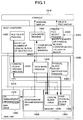
- FIG. 1 is a block diagram of a computer system applied with the present invention.
- a computer system of the present embodiment is structured including a disk unit 1030 capable of storing data with compression as a storage unit, a host computer 1020, and a console 1010 for transmitting information from the host computer 1020 to a user.
- the disk unit 1030 is structured of a compression/decompression unit 1050 for performing compression process and/or decompression process of data, a CPU 1070 for controlling read, write or the like of data in the disk unit 1030, a memory 1060 and a disk drive 1090 for storing compressed data.
- the host computer 1020 includes file delete process 1400, data write process 1420 on the host side and delete file select process 1440 for realizing various functions described in the present embodiment.
- the CPU 1070 of the disk unit 1030 is provided with respective functions of logical block release process 1410, data write process 1430 on the disk side, and physical block count notification process 1450 for realizing functions performed on the side of the disk unit 1030.
- Those functions that are provided in the host computer 1020 and the CPU 1070 are realized by software-like techniques with a program in the present embodiment.
- a logical block table 1200 and a free physical block table 1300 referred to by the CPU 1070 for achieving the functions described above provided in the CPU 1070 are stored.
- OS management information 1470 used for file management by the operating system on the host computer 1020 is stored.
- OS operating system
- arrow marks in thick solid lines, arrow marks in thick dotted lines and arrow marks in thin dotted lines show the flows of various information (data), respectively.
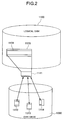
- Fig. 2 shows corresponding relationship between a data block on a logical disk 1100 that can be seen from the host computer 1020 and data blocks on a practical physical disk drive 1090 in the present embodiment.
- the capacity of the logical disk 1100 is 2 GB and the capacity of the disk drive 1090 is 1 GB taking the effect of data compression into consideration.
- the data on the logical disk 1100 are composed of a logical block 1120 having a size of 4 KB, and the data on the disk drive 1090 are composed of a physical block 1110 having a size of 512 B.
- the host computer 1020 makes access to the data stored in the disk unit 1030 in a unit of the logical block 1120.
- Decompressed data 1131 that are data of the logical block 1120 are compressed and become compressed data 1141, and the compressed data 1141 are divided and stored in a physical block 1112, a physical block 1113 and a physical block 1114 of the disk drive 1090. Since the size of the compressed data obtained by compressing data of the logical block is not fixed in general, the number of the physical blocks required for storing the compressed data becomes one to eight pieces. However, it is assumed that the compressed data 1141 do not become larger than the decompressed data 1131.
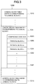
- Fig. 3 is a composition diagram of the logical block table 1200.
- the logical block table 1200 is a table that practically manages coordination between the logical block 1121 and the physical blocks 1112-4.
- the logical block table 1200 includes logical block number's worth of logical block table entries 1210 to 121N in the logical disk 1100. Respective logical block table entries 1210 to 121N correspond one to one to logical blocks in the logical disk 1100.
- a detailed configuration of the provided entry is shown with respect to the ith logical block table entry 121i only, but the other logical block table entry is composed in a similar manner. Thereafter, as an example, the logical block table entry 121i will be described assuming that it is the logical block table entry corresponding to the logical block 1120 shown in Fig. 2.
- the logical block table entry 121i includes a compressed data size 1120 and a plurality of physical block numbers 1230 to 1237 (8 pieces in the present embodiment).
- the compressed data size 1120 the data size of compressed data 1141 obtained by compressing the decompressed data 1131 of the logical block 1120 to which the logical block table entry 121i corresponds are stored. It is possible to obtain the number of physical blocks where the compressed data 1141 (of decompressed data 1131 of the logical block 1120) are stored by the data size held in the compressed data size 1220 (here, it is assumed that the number of physical blocks is 3).
- the physical block numbers of the physical blocks, where the compressed data 1141 are stored, are stored in the physical block numbers 1230 to 1237.
- the compressed data 1141 are stored in three physical blocks 1112, 1113 and 1114, and the block numbers of these three physical blocks are stored in from the first physical block number 1230 to the third physical block number 1232, respectively. Since no corresponding physical block does not exist in remaining physical block numbers, i.e., from the fourth physical block number 1233 to the eighth physical block number 1237, a value that is impossible as a physical block number such as -1 is stored.
- Fig. 4 is a composition diagram of a free physical block management table 1300.
- the free physical block management table 1300 is a table provided for managing free physical blocks of the disk drive 1090 where effective data are not stored.
- the free physical block table 1300 is composed of a number 1310 of free physical blocks, and a free physical block bit map 1320 showing whether free or not with 1 bit, respectively, with respect to all the physical blocks on the disk drive 1090.
- the bit corresponding to the physical block in use is set to 0, and the bit corresponding to the free physical block is set to 1.
- the file delete process 1400 of the host computer 1020 notifies the logical block release process 1410 of the CPU 1070 of the number of the logical block corresponding to the deleted file.
- the logical block release process 1410 rewrites the contents of the logical block table 1200 and the free physical block table 1300 on the memory 1060 so that the data of the deleted file are not held.
- the flow of information when the file is deleted is shown with arrow marks in thick solid lines.
- data write process 1420 of the host computer 1020 issues a write request of data to the disk unit 1030.
- data write process 1430 of the CPU 1070 when it is possible to store data in the disk drive 1090, compresses the write data by means of a compression/decompression unit 1050 and writes them into the disk drive 1090. Then, the process 1430 corrects the contents of the logical block table 1200 and the free physical block table 1300 on the memory 1060, and reports to the host computer 1020 of write completion.
- the data write process 1420 on the host side When there is a logical block that has newly become a free block, the data write process 1420 on the host side notifies the disk 1030 with compression function of the number of that logical block. The data write process 1430 on the disk side corrects the contents of the logical block table 1200 and the free physical block table 1300 and releases the physical block corresponding to the logical block that has become free. On the other hand, when data cannot be stored in the disk drive 1090, the data write process 1430 on the disk side reports the host computer 1020 of a warning. The data write process 1420 on the host side displays a warning on the console 1010 upon receipt of this report.
- the arrow marks in thin broken lines show the flow of information when a file name and capacity of a delete file are outputted to the console.
- physical block count notification process 1450 of the CPU 1070 investigates the count of physical blocks corresponding to respective logical blocks 1121 based on the logical block table 1200 stored in the memory 1060 and notifies the host computer 1020 of the result.
- delete file select process 1440 of the host computer 1020 makes the file and the logical block correspond to each other based on OS management information, and investigates how many physical blocks respective files correspond to, respectively, by collating the result of correspondence and the information that has been sent from the disk 1030 with compression function with each other.
- the file names are sorted in the order of count of corresponding physical blocks, and output them to the console 1010.
- Fig. 5 is a flowchart of the file delete process 1400 executed by the host computer 1020.
- a function for handling a disk unit having a compression function is added to the file delete process of the operating system.
- the host computer 1020 deletes the file required to be deleted.
- the host computer issues a logical block release command to the disk unit 1030, and notifies of the number of the logical block to which the deleted file has been allocated.
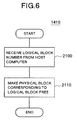
- Fig. 6 is a flowchart of the logical block release process 1410 executed by the CPU 1070.
- the CPU 1070 receives the number of the logical block from the host computer 1020.
- the logical block table 1200 and the free physical block table 1300 are rewritten, thereby to make the physical block corresponding to the logical block the number of which has been received free.
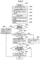
- Fig. 7 is a flowchart of the data write process 1430 executed by the CPU 1070.
- the CPU 1070 receives write data first from the host computer 1020 and stores them in the memory 1060 in a step 2200. Since these write data are in a non-compressed state, they are called decompressed data.
- the decompressed data stored in the memory 1060 are compressed by means of the compression/decompression unit 1050 so as to generate compressed data, which are stored again in the memory 1060.
- the CPU 1070 refers to a free physical block bit map 1320, and searches for free physical blocks in a number required for storing compressed data (a step 2220).
- the compressed data on the memory 1060 are written in a free physical block that has been found in the step 2220 (a step 2230).
- a step 2240 the CPU 1070 rewrites a logical block table entry corresponding to the logical block required for write, so that the logical block and the physical block are made to correspond to each other. Furthermore, in a step 2250, the CPU 1070 subtracts the number of written physical blocks from the number 1310 of free physical blocks stored in the free physical block table 1300, and sets 0 that shows an occupied state to the bit corresponding to the written physical block in the free physical block bit map 1320. Further, the CPU 1070 releases the physical block corresponding originally to the logical block required for write as a free block, adds the number to the number 1310 of free physical blocks, and set 1 to the corresponding bit in the free physical block bit map 1320.
- a step 2251 the CPU 1710 determines whether there are free physical blocks having capacity capable of storing write data based on the number 1310 of free physical blocks of the free physical block table 1300. Then, when the physical blocks are insufficient, the process jumps to a step 2252. When the physical blocks are not insufficient, the CPU 1070 determines whether free physical blocks remain sufficiently or not based on the number 1310 of free physical blocks of the free physical block table 1300. In the present embodiment, it is assumed to determine that the free physical blocks remain sufficiently when the number of the free physical blocks is 10% or more of the total number of physical blocks.
- a step 2280 it is determined whether a request for logical block release has been received from the host computer 1020 or not.
- the CPU 1070 completes write process 1430 when the request for logical block release has not been received.
- logical block release process 1410 shown in Fig. 6 is executed so as to complete write process 1430 in a step 2300.
- a step 2280 the CPU 1070 reports to the host computer 1020 of write completion, but, at this time, warning report is not made, but normal completion is reported, and the process jumps to the step 2290.
- a step 2252 it is reported to the host computer 1020 that free physical blocks are insufficient and the write data cannot be stored in a disk, thus completing the data write process 1430.
- Fig. 8 is a flowchart of data write process 1420 executed by the host computer 1020.
- the host computer 1020 issues write request to the disk unit 1030.
- write data are sent to the disk unit 1030.
- the host computer 1020 waits for completion of write process of the disk unit.
- the host computer 1020 determines in a step 2440 whether a warning showing that free physical blocks are small in number has been reported from the disk unit 1030 or not. In the case of no warning, the process jumps to a step 2460.
- the host computer 1020 When a warning has been reported, the host computer 1020 outputs a warning to the console 1010 and suggests a countermeasure to a user in a step 2450. In a step 2460, the host computer 1020 determines whether a logical block that has newly become free exists or not. This process is produced when a logical block allocated to a file by the operating system is changed by subscription of the file or the like. When any logical block that newly becomes free does not exist, the host computer 1020 completes the data write process 1420.
- a step 2470 the host computer issues a release request of the logical block to the disk unit 1030, and transmits the number of the logical block that has become a free block, thus the host computer 1020 completing the data write process 1420.
- the host computer 1020 notifies the disk unit 1030 of a logical block that becomes unnecessary to hold data so that useless data are not held in the disk unit 1030 whenever the file is deleted or whenever the logical block allocated to the file is altered by data write process. With this, it is possible to raise the utilization efficiency of the disk unit 1030.
- Fig. 9 shows an example of a warning displayed on the console 1010. It is notified to a user that free physical blocks are small in number by the display "FREE AREA OF DISK HAS BECOME SMALL".
- the display "DELETE USELESS FILE” suggests a user of a countermeasure thereafter. The user can increase the number of free physical blocks in the disk unit 1030 by deleting files determined to be useless.
- the display is a first item.
- file names are outputted in the order of number of corresponding physical blocks to the console 1010, so that the user may select those files that as many physical blocks as possible become free as the object of deletion when the file is erased.
- Fig. 10 is a flowchart of a process executed by the CPU 1070 according to the physical block count notification process 1450.
- the CPU 1070 investigates the number of physical blocks corresponding to respective logical blocks based on the logical block table 1200.
- the CPU 1070 transmits the number of physical blocks corresponding to respective logical blocks to the host computer 1020 in a step 2610.
- Fig. 11 is a flowchart of delete file select process 1440 executed by the host computer 1020.
- the host computer 1020 requests the disk unit 1030 to notify of the number of physical blocks corresponding to respective logical blocks.
- the host computer 1020 receives data showing the number of physical block corresponding to each logical block from the disk unit 1030.
- the logical block and the file are correlated with each other based on OS management information 1470, and the number of physical blocks holding data of a file is investigated with respect to each file.
- OS management information 1470 management information used by the OS for managing the file as it is as the OS management information 1470.
- the management information utilized by the OS includes information showing where in the storage unit such as a disk unit the data constituting respective files managed by the OS are stored, information showing the utilization state of the storage area in the storage unit and so on.
- the logical disk 1100 corresponds to the storage unit mentioned herein.
- the OS management information 1470 holds the information showing the corresponding relationship between respective files and the logical blocks where the data of these files are stored and the utilization state of logical blocks.
- the host computer 1020 outputs file names to the console 1010 in the order of number of corresponding physical blocks in the step 2730.
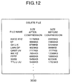
- Fig. 12 is an example of a picture output of a delete file.
- Information composed of file name, file size after data compression and file size before data compression is displayed in order of file size after data compression for each file.
- the file size after data compression is obtainable by multiplying the number of physical blocks corresponding to the file by the size of the physical block. Further, the file size before data compression is obtainable from the OS management information 1470.
- a user is able to learn which file occupies the disk unit 4030 largely by looking at the console, and only needs to select the file to be deleted with this information as one of selecting materials.
- a delete instruction is notified to the disk and the physical blocks corresponding to logical blocks allocated to the deleted file are released whenever the file is deleted. Since this process is executed synchronously with delete process of the file or write process, however, there is such a drawback that the overhead attendant upon synchronization of the process becomes larger. Further, there is also such a problem that it is required to notify the disk of the logical block that has become no longer necessary to hold the data and to incorporate the function of executing the process for making the corresponding physical block free into the OS, and the reconstruction scale is large. An embodiment in which those problems have been solved is shown hereunder.
- Fig. 13 is a block diagram of a computer system in a second embodiment.
- the overhead of delete process or write process of the file is reduced, thereby to make the reconstruction scale of the OS smaller.
- a free area recovering application program 1460 for writing data of high compressibility collectively in all the logical blocks that do not need to hold data when usable free physical blocks become smaller in quantity without notifying the disk of deletion of the file whenever it occurs is provided.
- the number of usable free physical blocks 1110 is increased by the process 1460, thereby to cope with the problem of the utilization efficiency of the disk 1030 with a compression function.
- arrow marks in thick dotted lines show the flow of information (data) at data write time.
- a data write process 1421 of the host computer 1020 issues write request of data to the disk unit 1030.
- Data write process 1431 of the CPU 1070 when data can be stored on the disk drive 1090, compresses write data by a compression/decompression unit 1050 and writes the result thereof in the disk drive 1090 in accordance with write request. Then, the contents of the logical block table 1200 and the free physical block table 1300 of the memory 1060 are corrected, and write completion is reported to the host computer 1020.
- the data write process 1431 on the disk side reports the host computer 1020 of a warning.
- the data write process 1421 on the host side displays a warning on the console 1010 upon receipt of this report.
- the physical block count notification process 1450 of the CPU 1070 investigates the number of physical blocks corresponding to respective logical blocks 1120 based on the logical block table 1200 located in the memory 1060 and informs the number to the host computer 1020.
- the delete file select process 1440 of the host computer 1020 has the file and the logical block 1120 correspond to each other based on OS management information 1470, and collates this with the received information with each other, thereby to investigate how many physical blocks each file corresponds to, respectively.
- File names are sorted in order of number of corresponding physical blocks, and outputted to the console 1010.
- Arrow marks in thin solid lines show the flow of information when the free area recovering application program 1460 of the host computer 1020 executes the process.
- logical blocks that are not used by the operating system are determined based on the OS management information 1470.
- the free area recovering application program 1460 issues a write request to the data write process 1421 on the host side so as to write the data of all 0 in all the virgin logical blocks based on the determination.
- reference numerals used in Fig. 1 are used as they are for those that correspond to the components shown in Fig. 1.
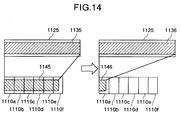
- Fig. 14 is a principle diagram showing a state that free physical blocks increase by the process executed by the free area recovering application program 1460.
- 1125 represents a logical block, and decompressed data 1135 are stored there in a state before the process by the free area recovering application program 1460 is executed.
- the decompressed data 1135 are compressed by compression process and become compressed data 1145.
- These compressed data 1145 are stored in six pieces of physical blocks 1110a to 1110f.
- dummy data 1136 are written in the logical block 1125.
- the dummy data 1136 are compressed and become compressed data 1146, and stored in one physical block 1110a.
- five physical blocks 1110b to 1110f among six physical blocks where compressed data 1145 obtained by compressing decompressed data 1135 before recovering process is performed have been stored are released as free physical blocks.
- those data capable of obtaining comparatively high compressibility such as those that all the bits are composed of 0 are used as the dummy data.
- description is made assuming that the dummy data are compressed down to the size that is installed in one physical block by compression process, but this is varied depending on the data used as the dummy data and algorithm of compression used for compression process.
- the data having compressibility higher than at least the compressibility of average data are used as the data used as the dummy data. The higher the compressibility of the data is, the more the physical blocks can be released as free areas.
- the host computer 1020 needs not to inform the disk unit 1030 of deletion of the logical block corresponding to the file deleted synchronously with the file delete process. Accordingly, the file delete process executed by the host computer 1020 is performed in a same manner to conventional file delete process. In brief, it is possible to use file delete process included in a conventional operating system operating on the host computer 1020 as it is in the present embodiment.
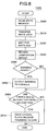
- Fig. 15 shows a flowchart of data write process 1431 executed by the CPU 1070 of the disk unit 1030.
- the same reference numerals as the step numbers used in Fig. 7 are used with respect to the step where the same process as the data write process 1430 of the CPU 1070 in the first embodiment is performed. Since the logical block that has become unnecessary at time of data write to the file is not released in the data write process 1431 of the present embodiment, the processes in the steps 2290 and 2300 shown in Fig. 7 become unnecessary. In other steps, the process similar to that in a step corresponding to Fig. 7 in the first embodiment is performed.
- Fig. 16 is a flowchart showing the flow of the data write process 1421 executed by the host computer 1020.
- the same numbers as the step numbers used in Fig. 8 are used with respect to the steps where the same process as the data write process 1420 of the host computer 1020 in the first embodiment is performed.
- the data write process 1421 of the present embodiment the logical block that has become unnecessary at time of data write to the file is not released similarly to the data write process executed by the CPU 1070 of the disk unit 1030. Therefore, processes in the steps 2460 and 2470 shown in Fig. 8 become unnecessary. With respect to other steps, the process similar to the corresponding steps in Fig. 8 in the first embodiment is performed.
- Fig. 17 is a display example of a warning picture outputted to the console 1010 in the present embodiment.
- the physical block in the disk unit 1030 is not released at time of file delete, so it is impossible to newly increase usable physical blocks by deleting files.
- a warning picture 3010 in which the display "RUN FREE AREA RECOVERING APPLICATION" is added to the warning picture 3000 (Fig. 9) in the first embodiment is used as a warning picture displayed when the number of the newly usable physical blocks becomes smaller.
- a user can learn the timing of executing the free area recovering application program by the warning picture 3010 being displayed on the console 1010.
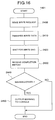
- Fig. 18 is a flowchart of the free area recovering application program 1460.
- a step 2500 logical blocks that are not used are determined based on OS management information 1470 of the host computer 1020.
- a step 2510 write process of dummy data to a logical block determined as unused is performed.
- the write process of dummy data may be executed by the data write processes 1420 and 1430 as a normal data write process complying with a write request issued by the free area recovering application program 1460.
- the storage unit having a compression function reports to the host computer of a warning when the number of physical blocks capable of allocating new logical blocks becomes smaller and it is determined that physical use area approaches full.
- the host computer receives the report and outputs it to the console.
- a user can notice that the physical use area approaches full by looking at the warning outputted to the console. It is possible for a user to prevent in advance the physically usable storage area from becoming full by instructing deletion of a file optionally or recovering process of a physical block based on this warning.
Landscapes
- Engineering & Computer Science (AREA)
- Theoretical Computer Science (AREA)
- Human Computer Interaction (AREA)
- Physics & Mathematics (AREA)
- General Engineering & Computer Science (AREA)
- General Physics & Mathematics (AREA)
- Signal Processing (AREA)
- Information Retrieval, Db Structures And Fs Structures Therefor (AREA)
- Memory System (AREA)
Applications Claiming Priority (2)
| Application Number | Priority Date | Filing Date | Title |
|---|---|---|---|
| JP177986/94 | 1994-07-29 | ||
| JP6177986A JPH0844498A (ja) | 1994-07-29 | 1994-07-29 | 圧縮機能付き記憶装置及びそれを有するコンピュータシステム |
Publications (2)
| Publication Number | Publication Date |
|---|---|
| EP0694831A2 true EP0694831A2 (de) | 1996-01-31 |
| EP0694831A3 EP0694831A3 (de) | 1997-08-27 |
Family
ID=16040539
Family Applications (1)
| Application Number | Title | Priority Date | Filing Date |
|---|---|---|---|
| EP95111704A Withdrawn EP0694831A3 (de) | 1994-07-29 | 1995-07-25 | Mit einer Kompressionsfunktion versehenes Rechnersystem mit einer Speichereinheit und Verwaltungsverfahren eines Speicherbereichs dafür |
Country Status (2)
| Country | Link |
|---|---|
| EP (1) | EP0694831A3 (de) |
| JP (1) | JPH0844498A (de) |
Cited By (8)
| Publication number | Priority date | Publication date | Assignee | Title |
|---|---|---|---|---|
| WO2000077613A3 (en) * | 1999-06-14 | 2001-07-05 | Wind River Internat Inc | Method and system for managing and using persistent storage |
| US6490616B1 (en) | 1999-06-14 | 2002-12-03 | Wind River International, Ltd. | Method and apparatus for incremental download from server to client |
| WO2002052396A3 (en) * | 2000-12-22 | 2004-03-25 | Koninkl Philips Electronics Nv | Method and system for reducing fragmentation |
| US6857015B1 (en) | 1999-06-14 | 2005-02-15 | Wind River International, Ltd. | Method and system for remotely observing and controlling objects |
| EP0916131A4 (de) * | 1997-03-07 | 2005-09-07 | Microsoft Corp | Verfahren zum freimachen von plattenspeicherplatz in einem dateisystem |
| WO2005111803A3 (en) * | 2004-04-30 | 2006-06-01 | Network Appliance Inc | Extension of a system and method for write allocation within a write anywhere file layout file system |
| US8122219B2 (en) | 2009-07-22 | 2012-02-21 | International Business Machines Corporation | Storage allocation |
| CN116339622A (zh) * | 2023-02-20 | 2023-06-27 | 深圳市数存科技有限公司 | 一种基于块级的数据压缩系统及方法 |
Families Citing this family (5)
| Publication number | Priority date | Publication date | Assignee | Title |
|---|---|---|---|---|
| JP2001043115A (ja) * | 1999-07-29 | 2001-02-16 | Nec Corp | ファイル管理システム及びファイル管理方法 |
| US6681305B1 (en) * | 2000-05-30 | 2004-01-20 | International Business Machines Corporation | Method for operating system support for memory compression |
| US6877081B2 (en) | 2001-02-13 | 2005-04-05 | International Business Machines Corporation | System and method for managing memory compression transparent to an operating system |
| JP4267353B2 (ja) | 2003-03-28 | 2009-05-27 | 株式会社日立製作所 | データ移行支援システム、および、データ移行支援方法 |
| KR20220024206A (ko) * | 2019-07-02 | 2022-03-03 | 마이크로소프트 테크놀로지 라이센싱, 엘엘씨 | 하드웨어 기반 메모리 압축 |
Citations (1)
| Publication number | Priority date | Publication date | Assignee | Title |
|---|---|---|---|---|
| WO1991020025A1 (en) | 1990-06-18 | 1991-12-26 | Storage Technology Corporation | Deleted data file space release system for a dynamically mapped virtual data storage subsystem |
Family Cites Families (2)
| Publication number | Priority date | Publication date | Assignee | Title |
|---|---|---|---|---|
| US4528624A (en) * | 1981-03-25 | 1985-07-09 | International Business Machines Corporation | Method and apparatus for allocating memory space based upon free space in diverse memory devices |
| US5247638A (en) * | 1990-06-18 | 1993-09-21 | Storage Technology Corporation | Apparatus for compressing data in a dynamically mapped virtual data storage subsystem |
-
1994
- 1994-07-29 JP JP6177986A patent/JPH0844498A/ja active Pending
-
1995
- 1995-07-25 EP EP95111704A patent/EP0694831A3/de not_active Withdrawn
Patent Citations (1)
| Publication number | Priority date | Publication date | Assignee | Title |
|---|---|---|---|---|
| WO1991020025A1 (en) | 1990-06-18 | 1991-12-26 | Storage Technology Corporation | Deleted data file space release system for a dynamically mapped virtual data storage subsystem |
Cited By (14)
| Publication number | Priority date | Publication date | Assignee | Title |
|---|---|---|---|---|
| EP0916131A4 (de) * | 1997-03-07 | 2005-09-07 | Microsoft Corp | Verfahren zum freimachen von plattenspeicherplatz in einem dateisystem |
| WO2000077613A3 (en) * | 1999-06-14 | 2001-07-05 | Wind River Internat Inc | Method and system for managing and using persistent storage |
| US6490616B1 (en) | 1999-06-14 | 2002-12-03 | Wind River International, Ltd. | Method and apparatus for incremental download from server to client |
| US6857015B1 (en) | 1999-06-14 | 2005-02-15 | Wind River International, Ltd. | Method and system for remotely observing and controlling objects |
| WO2002052396A3 (en) * | 2000-12-22 | 2004-03-25 | Koninkl Philips Electronics Nv | Method and system for reducing fragmentation |
| US7430571B2 (en) | 2004-04-30 | 2008-09-30 | Network Appliance, Inc. | Extension of write anywhere file layout write allocation |
| WO2005111803A3 (en) * | 2004-04-30 | 2006-06-01 | Network Appliance Inc | Extension of a system and method for write allocation within a write anywhere file layout file system |
| US7970770B2 (en) | 2004-04-30 | 2011-06-28 | Netapp, Inc. | Extension of write anywhere file layout write allocation |
| US8533201B2 (en) | 2004-04-30 | 2013-09-10 | Netapp, Inc. | Extension of write anywhere file layout write allocation |
| US8903830B2 (en) | 2004-04-30 | 2014-12-02 | Netapp, Inc. | Extension of write anywhere file layout write allocation |
| US9430493B2 (en) | 2004-04-30 | 2016-08-30 | Netapp, Inc. | Extension of write anywhere file layout write allocation |
| US8122219B2 (en) | 2009-07-22 | 2012-02-21 | International Business Machines Corporation | Storage allocation |
| CN116339622A (zh) * | 2023-02-20 | 2023-06-27 | 深圳市数存科技有限公司 | 一种基于块级的数据压缩系统及方法 |
| CN116339622B (zh) * | 2023-02-20 | 2023-11-14 | 深圳市数存科技有限公司 | 一种基于块级的数据压缩系统及方法 |
Also Published As
| Publication number | Publication date |
|---|---|
| EP0694831A3 (de) | 1997-08-27 |
| JPH0844498A (ja) | 1996-02-16 |
Similar Documents
| Publication | Publication Date | Title |
|---|---|---|
| US8812449B2 (en) | Storage control system and method | |
| US8271444B2 (en) | Storage control device to backup data stored in virtual volume | |
| US7739463B2 (en) | Storage system and method for acquisition and utilization of snapshots | |
| KR100404555B1 (ko) | 데이터 프로세서 제어형 데이터 저장 시스템, 동적 재동기화 방법, 및 컴퓨터 프로그램을 포함하는 컴퓨터 판독 가능한 기록 매체 | |
| US6000009A (en) | Method and apparatus for allocation of disk memory space for compressed data records | |
| US7257675B2 (en) | Disk array device having snapshot simulation function | |
| JPH08101782A (ja) | 記憶管理システム及び方法 | |
| EP0694831A2 (de) | Mit einer Kompressionsfunktion versehenes Rechnersystem mit einer Speichereinheit und Verwaltungsverfahren eines Speicherbereichs dafür | |
| JPH06139120A (ja) | ファイルの更新方式 | |
| US7032093B1 (en) | On-demand allocation of physical storage for virtual volumes using a zero logical disk | |
| US7032085B2 (en) | Storage system with a data sort function | |
| JPH11143779A (ja) | 仮想記憶装置におけるページング処理システム | |
| EP0720085A2 (de) | Kompressionsüberwachungssystem zum Steuern physikalischer Speicherbereichszuordnung in einem logischen abgebildeten Datenspeicher | |
| US7752405B2 (en) | Data recording apparatus, program product, and data recording method | |
| EP0518311A2 (de) | Dateienspeicherverfahren, Dateienzugriffsverfahren und verteiltes Verarbeitungssystem, welches diese Verfahren benutzt | |
| JPH08314639A (ja) | 情報記録再生装置 | |
| JP2006039942A (ja) | 階層記憶システムにおけるファイル管理装置及びそのファイル管理方法 | |
| JPH09223049A (ja) | ディスクアレイ装置 | |
| JPH06110759A (ja) | ファイルシステム | |
| JP2001265626A (ja) | ファイル管理方法、データ処理装置並びに記憶媒体 | |
| JP3022829B2 (ja) | 記憶装置の自動割り当て装置 | |
| JPH06348572A (ja) | マルチ機構ディスクシステム | |
| JPH04350738A (ja) | ディスクスペース管理方式 | |
| JPH06259292A (ja) | 外部記憶装置のオンラインガーベッジコレクション方法 | |
| JP2001177800A (ja) | ビデオサーバおよびプログラム記録媒体 |
Legal Events
| Date | Code | Title | Description |
|---|---|---|---|
| PUAI | Public reference made under article 153(3) epc to a published international application that has entered the european phase |
Free format text: ORIGINAL CODE: 0009012 |
|
| AK | Designated contracting states |
Kind code of ref document: A2 Designated state(s): DE FR GB |
|
| PUAL | Search report despatched |
Free format text: ORIGINAL CODE: 0009013 |
|
| AK | Designated contracting states |
Kind code of ref document: A3 Designated state(s): DE FR GB |
|
| 17P | Request for examination filed |
Effective date: 19970412 |
|
| R17P | Request for examination filed (corrected) |
Effective date: 19970912 |
|
| STAA | Information on the status of an ep patent application or granted ep patent |
Free format text: STATUS: THE APPLICATION HAS BEEN WITHDRAWN |
|
| 18W | Application withdrawn |
Withdrawal date: 19980209 |