EP0694903A2 - Circuit récepteur - Google Patents
Circuit récepteur Download PDFInfo
- Publication number
- EP0694903A2 EP0694903A2 EP95111279A EP95111279A EP0694903A2 EP 0694903 A2 EP0694903 A2 EP 0694903A2 EP 95111279 A EP95111279 A EP 95111279A EP 95111279 A EP95111279 A EP 95111279A EP 0694903 A2 EP0694903 A2 EP 0694903A2
- Authority
- EP
- European Patent Office
- Prior art keywords
- signal
- background noise
- level
- output
- circuit
- Prior art date
- Legal status (The legal status is an assumption and is not a legal conclusion. Google has not performed a legal analysis and makes no representation as to the accuracy of the status listed.)
- Granted
Links
- 238000001514 detection method Methods 0.000 claims abstract description 34
- 230000008859 change Effects 0.000 claims abstract description 15
- 230000004044 response Effects 0.000 claims description 6
- 230000007704 transition Effects 0.000 claims description 6
- 230000035807 sensation Effects 0.000 abstract description 10
- 238000005070 sampling Methods 0.000 abstract description 7
- 230000006870 function Effects 0.000 abstract description 2
- 238000010586 diagram Methods 0.000 description 4
- 230000005236 sound signal Effects 0.000 description 3
- 230000004048 modification Effects 0.000 description 2
- 238000012986 modification Methods 0.000 description 2
- 230000008929 regeneration Effects 0.000 description 2
- 238000011069 regeneration method Methods 0.000 description 2
- 230000003044 adaptive effect Effects 0.000 description 1
- 239000000470 constituent Substances 0.000 description 1
- 230000008034 disappearance Effects 0.000 description 1
- 230000000694 effects Effects 0.000 description 1
- 238000003780 insertion Methods 0.000 description 1
- 230000037431 insertion Effects 0.000 description 1
- 238000000034 method Methods 0.000 description 1
- 230000008569 process Effects 0.000 description 1
Images

Classifications
-
- G—PHYSICS
- G10—MUSICAL INSTRUMENTS; ACOUSTICS
- G10L—SPEECH ANALYSIS TECHNIQUES OR SPEECH SYNTHESIS; SPEECH RECOGNITION; SPEECH OR VOICE PROCESSING TECHNIQUES; SPEECH OR AUDIO CODING OR DECODING
- G10L19/00—Speech or audio signals analysis-synthesis techniques for redundancy reduction, e.g. in vocoders; Coding or decoding of speech or audio signals, using source filter models or psychoacoustic analysis
- G10L19/012—Comfort noise or silence coding
-
- G—PHYSICS
- G10—MUSICAL INSTRUMENTS; ACOUSTICS
- G10L—SPEECH ANALYSIS TECHNIQUES OR SPEECH SYNTHESIS; SPEECH RECOGNITION; SPEECH OR VOICE PROCESSING TECHNIQUES; SPEECH OR AUDIO CODING OR DECODING
- G10L25/00—Speech or voice analysis techniques not restricted to a single one of groups G10L15/00 - G10L21/00
- G10L25/93—Discriminating between voiced and unvoiced parts of speech signals
Definitions
- the present invention relates to a receiving circuit and, more particularly, to a receiving circuit having the function of inserting a background noise.
- a receiving circuit is applied widely to a digital cordless telephone set, employing an adaptive differential pulse-code modulation (ADPCM) codec or the like.
- ADPCM adaptive differential pulse-code modulation
- FIG. 3 there is shown the configuration of an internal automatic level setting circuit for the background noise on the receiver side in a conventional cordless telephone set.
- This circuit includes a voice/silence detection circuit 1 which detects whether a received speech signal 101 belongs to a voiced or a voiceless state, a signal level detection circuit 2 which detects the signal level of the received speech signal 101 at specified timings, a background noise generating circuit 6, and a switch or selector 7 from which an audio signal 108 is derived.
- the received speech signal 101 is input in common to the voice/silence detection circuit 1, the signal level detection circuit 2, and the selector 7.
- the circuit 1 observes the conditions of the received speech signal 101 and outputs a voice/silence detection signal 103 which is at a high level (high potential) when the received speech signal is voiced and is at a low level (low potential) when it is voiceless.
- This 103 is supplied in common to the signal level detection circuit 2 and the selector 7.
- the circuit 2 detects the signal level of the received speech signal 101 at the timing (referred to as "background noise level update timing") of transition of the voice/silence signal 103 from the high level to the low level, outputs a detected level signal 102 which has a magnitude or amplitude proportional to the detected signal level, where the detected level signal 102 is input to the background noise generating circuit 6.
- the circuit 6 generates and outputs an internal background noise signal 107 which is a background noise that is proportional to the amplitude of the detected level signal 102. This noise signal 107 is in turn supplied to the selector 7.
- the selector 7 selects the received speech signal 101 when the signal 103 is at the high level (namely, when it is voiced), and selects the internal background noise signal 107 when the voice/silence decision signal 103 is at the low level (namely, when it is voiceless), and outputs the selected signal as the audio signal 108.
- the signal level of the received speech signal 101 is detected at the timing of transition of the received speech signal 101 from voiced to voiceless condition, and a background noise with a level corresponding to the level of the detected signal is regenerated and is inserted to the receiver circuit during the voiceless period as an audio signal 108.
- a background noise with a level corresponding to the level of the detected signal is regenerated and is inserted to the receiver circuit during the voiceless period as an audio signal 108.
- the background noise proportional to the detected signal level is regenerated at every background noise level update timing, so that when an impulse noise or the like is generated at that timing, a background noise proportional to the level of the impulse noise is created, generating an unnatural background noise which gives rise to an aurally incongruous sensation such as one caused by a sudden change in the background noise.
- a receiving circuit comprises a voice/silence detection circuit detecting whether a received speech signal is in a voiced or a voiceless state, a signal level detection circuit detecting the signal level of the received signal, a background noise generator generating a background noise signal, a selector selecting the received signal during a voice period and selecting and outputting the output signal of the background noise signal during a voiceless period, a holding circuit holding the signal level output of the preceding sampling detected by the signal level detection circuit, and a comparator for comparing the output of the signal level detection circuit with the signal level output at the preceding timing held by the holding circuit.
- the background noise outputting means is so controlled as to output a background noise signal having a level obtained by adding to or subtracting from the background noise level at the preceding timing a specified noise level determined in advance in response to the comparison result of the comparator.
- This invention is characterized in that it is provided with a means which, in response to the comparison result, controls the background noise outputting means to output a background noise so as not to deviate from the background noise level at the preceding timing by more than a specified level.
- this invention it is preferable in this invention to have a means which controls so as to output the background noise level as it is when the difference between the present signal level output of the signal level detection means and the output of the signal level held in the detected level holding means falls within the range of the level defined by predetermined upper and lower limits, output a background noise with a level lower by a specified amount than the background noise level at the preceding timing when the difference is smaller than the lower limit, and output a background noise with a level higher by a specified amount than the background noise level at the preceding timing when the difference is greater than the upper limit.
- the detected level holding means holds the signal level output ((n-1)th sample) of the signal level detection means at the timing where the decision output of the voice/silence decision means of the received signal makes a transition from a voiced to a voiceless state
- the comparison means outputs the difference between the present signal level output (n-th sample) of the signal level detection means and the signal level output ((n-1)th sample) held in the detected level holding means as the comparison result.
- an ADPCM codec equipped with an internal automatic level setting circuit for the receiver side background noise, consisting of a circuit for deciding whether the received signal is in a voiced or a voiceless state, a circuit for detecting the signal level of the received speech signal, a background noise generating circuit for outputting a background noise, and a switch for selecting the received speech signal or the background noise generated by the background noise generating circuit as an aural signal
- this invention provides an ADPCM codec which is characterized in that it is equipped with a means for comparing the present sample value with the sample value at the preceding timing, of the level of the received speech signal, and a means for controlling the background noise generating circuit so as to output the present background noise which does not deviate from the background noise level of the preceding sampling by more than a specified amount.
- the level change in the background noise regenerated on the receiver side is contained within a range specified in advance, so that this invention is capable of providing a background noise free from incongruous aural sensation by restricting the deviation of the present level of the background noise from the level of the preceding sampling only by one step even when an impulse noise is generated at the time of updating the background noise level.
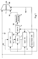
- FIG. 1 there is shown a block diagram indicative of an embodiment of this invention, in which the same constituents as those shown in FIG. 3 are denoted by the same reference numerals.
- the circuit as shown in FIG. 1 includes a voice/silence detection circuit 1 which receives a speech signal 101 and detects whether it is in a voiced or a voiceless state.
- the signal 101 is further supplied to a signal level detection circuit 2 which detects the signal level of the speech signal 101 at specified timings and produces a detection signal 102 thereof.
- This signal 102 is supplied to a holding circuit 3 and temporarily held therein until the circuit 2 operates at the next sampling timing.
- a comparator circuit 4 a control circuit 5
- a background noise generating circuit 6 and a selector 7.
- the speech signal 101 is supplied in common to the voice/silence detection circuit 1, the signal level detection circuit 2, and the selector 7.
- the circuit 1 observes the conditions of the received speech signal 101, and outputs a voice/silence decision signal 103 which is at a high level (high potential) when the received speech signal is voiced and is at a low level (low potential) when it is voiceless.
- This signal 103 is supplied to the signal level detection circuit 2, the control circuit 5, and the selector 7.
- the signal level detection circuit 2 detects the signal level of the received speech signal 101 at the update timing of the background noise level where the signal 103 makes a transition from the high level to the low level, and outputs the detected level signal 102 which is proportional to the signal level.
- the detected level signal 102 is in turn supplied to the preceding detected level holding circuit 3 and the comparator circuit 4.
- the holding circuit 3 fetches and thus temporarily holds the detected level signal 102 every background noise level update timing, and outputs the previously-held level signal as a preceding detected level signal 104 which is in turn supplied to the comparator circuit 4.
- the comparator circuit 4 detects the level variation by comparing the magnitude of the detected level signal 102 and the preceding detected level signal 104 at every background noise level update timing to output the variation (difference value) as a variation signal 105.
- This signal 105 is then input to the control circuit 5.
- the signal 105 thus represents a difference between n-th detected signal and (n-1)th detected signal.
- the control circuit 5 responds to signal 105 and controls its output signal 106 such that the background noise level signal 106, which has been produced in response to the previous ((n-1)th) operation, is raised or lowered by a predetermined specified amount, or not changed.
- This noise level signal 106 is generated and supplied to the selector 7.
- This selector 7 selects the received speech signal 101 when the voice/silence detection signal 103 is at the high level (namely, when it is voiced) and selects the internal background noise 107 when the signal 103 is at the low level (namely, when it is voiceless), and outputs the selected one as an output signal 108.
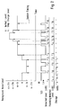
- FIG. 2 shows a timing chart which represents an example of the changing situation versus the time axis, of the background noise level signal 106 which is the output of the control circuit 5, and the changing process of the voice/silence detection signal 103 corresponding to the time axis is also shown in the figure.
- the pair (combination) of the detected level signal 102 (r n ) and the preceding detected level signal 104 (r n-1 ) at every background noise level update timing (shown by the broken line in the figure) where the voice/silence signal 103 makes a transition from the high level to the low level is shown in time sequence in FIG. 2.
- the suffix n of the detected level signal r n corresponds to the number of times of occurrence of the background noise.
- the variation signal 105 output from the comparator circuit 4 is represented in FIG. 2 as the level variation r n - r n-1 .
- the control circuit 5 When the level variation r n - r n-1 is smaller than a minimum value r min specified in advance (namely, when r min > r n - r n-1 ), the control circuit 5 outputs the signal obtained by lowering the level of the preceding ((n-1)th) background noise level by a predetermined specified level value b as the present (n-th) background noise level signal 106. This signal 106 is held by the control circuit 5 until the next background noise level update timing.
- the control circuit 5 holds the level of the present (n-th) background noise level signal 106 at the same level as that of the preceding ((n-1)th) background noise level signal.
- the control circuit 5 outputs the signal obtained by raising the level of the preceding ((n-1)th) background noise level signal by the predetermined specified level b as the present (n-th) background noise level signal 106.
- the maximum value r max and the minimum value r min may be set to be variable (provided that r min ⁇ r max ).
- the control circuit 5 determines the level of the present (n-th) background noise signal 106 so as to be changed from that of the preceding ((n-1)th) background level signal by one step unit ( ⁇ b) at the most, and holds the value until the next background noise level update timing. Therefore, even when the detected level signal 102 undergoes a sudden change due to generation of an impulse noise at a time of signal level detection, the change in the background noise level signal 106 is positively confined within a specified range. In other words, as shown in FIG.
- the background noise level signal 106 undergoes a change of a maximum of one step unit based on the level variation r n - r n-1 , so that there will not be output a signal with large level change and steep gradient, proportional to an impulse noise or the like, and the background noise level signal 106 will follow slowly the changes in the detected level signal 102.
- the level of the internal background noise signal 107 will not undergo a sudden change even when an impulse noise is generated at an updating time of the background noise level during regeneration of a background noise on the receiver side, so that this embodiment is capable of generating a natural background noise free from incongruous aural sensation.
- the level of the background noise undergoes a change only within a specified range, without a sudden change, even when an impulse noise is generated at an updating time of the background noise during regeneration of a background noise on the receiver side. Therefore, this invention exhibits an effect that it can generate a background noise free from incongruous aural sensation.
- the device is controlled such that it selects either one of the signal obtained, by adding or subtracting a predetermined specified level value to or from, or by holding the level at the same value as, the background noise output at one sampling period earlier. Therefore, even when there is generated an impulse noise at a signal detection time, the signal level is changed from the background noise level at one sampling period earlier by one step portion at the most, so that it is possible to generate a background noise which has no sudden change and is free from incongruous aural sensation.
- an impulse noise or the like it is possible to suppress an impulse noise or the like to be output as a background noise, and generate a natural background noise free from incongruous aural sensation by a simple constitution of adding a preceding detected level holding circuit, a comparator circuit which outputs the variation in the detected level signal, and a control circuit which updates the background noise level at every background noise level update timing.
Landscapes
- Engineering & Computer Science (AREA)
- Computational Linguistics (AREA)
- Signal Processing (AREA)
- Health & Medical Sciences (AREA)
- Audiology, Speech & Language Pathology (AREA)
- Human Computer Interaction (AREA)
- Physics & Mathematics (AREA)
- Acoustics & Sound (AREA)
- Multimedia (AREA)
- Noise Elimination (AREA)
Applications Claiming Priority (3)
| Application Number | Priority Date | Filing Date | Title |
|---|---|---|---|
| JP6189054A JP2586827B2 (ja) | 1994-07-20 | 1994-07-20 | 受信装置 |
| JP18905494 | 1994-07-20 | ||
| JP189054/94 | 1994-07-20 |
Publications (3)
| Publication Number | Publication Date |
|---|---|
| EP0694903A2 true EP0694903A2 (fr) | 1996-01-31 |
| EP0694903A3 EP0694903A3 (fr) | 1997-10-22 |
| EP0694903B1 EP0694903B1 (fr) | 2001-10-17 |
Family
ID=16234524
Family Applications (1)
| Application Number | Title | Priority Date | Filing Date |
|---|---|---|---|
| EP95111279A Expired - Lifetime EP0694903B1 (fr) | 1994-07-20 | 1995-07-18 | Circuit récepteur |
Country Status (4)
| Country | Link |
|---|---|
| US (1) | US5692017A (fr) |
| EP (1) | EP0694903B1 (fr) |
| JP (1) | JP2586827B2 (fr) |
| DE (1) | DE69523231T2 (fr) |
Cited By (2)
| Publication number | Priority date | Publication date | Assignee | Title |
|---|---|---|---|---|
| WO1999021167A1 (fr) * | 1997-10-16 | 1999-04-29 | Motorola Limited | Transitions en douceur du bruit de fond |
| US6873604B1 (en) * | 2000-07-31 | 2005-03-29 | Cisco Technology, Inc. | Method and apparatus for transitioning comfort noise in an IP-based telephony system |
Families Citing this family (16)
| Publication number | Priority date | Publication date | Assignee | Title |
|---|---|---|---|---|
| US6212245B1 (en) * | 1995-07-13 | 2001-04-03 | Canon Kabushiki Kaisha | Communication apparatus |
| US5881373A (en) * | 1996-08-28 | 1999-03-09 | Telefonaktiebolaget Lm Ericsson | Muting a microphone in radiocommunication systems |
| JP2001242896A (ja) * | 2000-02-29 | 2001-09-07 | Matsushita Electric Ind Co Ltd | 音声符号化/復号装置およびその方法 |
| US6941161B1 (en) | 2001-09-13 | 2005-09-06 | Plantronics, Inc | Microphone position and speech level sensor |
| GB0214729D0 (en) * | 2002-06-26 | 2002-08-07 | Koninkl Philips Electronics Nv | Digital receiver arrangement and related method |
| GB2451828A (en) * | 2007-08-13 | 2009-02-18 | Snell & Wilcox Ltd | Digital audio processing method for identifying periods in which samples may be deleted or repeated unobtrusively |
| US9818118B2 (en) * | 2008-11-19 | 2017-11-14 | Visa International Service Association | Transaction aggregator |
| US9841282B2 (en) | 2009-07-27 | 2017-12-12 | Visa U.S.A. Inc. | Successive offer communications with an offer recipient |
| US20110047072A1 (en) * | 2009-08-07 | 2011-02-24 | Visa U.S.A. Inc. | Systems and Methods for Propensity Analysis and Validation |
| US20110087546A1 (en) * | 2009-10-09 | 2011-04-14 | Visa U.S.A. Inc. | Systems and Methods for Anticipatory Advertisement Delivery |
| US9342835B2 (en) * | 2009-10-09 | 2016-05-17 | Visa U.S.A | Systems and methods to deliver targeted advertisements to audience |
| US20110093335A1 (en) * | 2009-10-19 | 2011-04-21 | Visa U.S.A. Inc. | Systems and Methods for Advertising Services Based on an SKU-Level Profile |
| US20110093324A1 (en) | 2009-10-19 | 2011-04-21 | Visa U.S.A. Inc. | Systems and Methods to Provide Intelligent Analytics to Cardholders and Merchants |
| US8626705B2 (en) * | 2009-11-05 | 2014-01-07 | Visa International Service Association | Transaction aggregator for closed processing |
| US20110125565A1 (en) * | 2009-11-24 | 2011-05-26 | Visa U.S.A. Inc. | Systems and Methods for Multi-Channel Offer Redemption |
| US10007915B2 (en) | 2011-01-24 | 2018-06-26 | Visa International Service Association | Systems and methods to facilitate loyalty reward transactions |
Family Cites Families (8)
| Publication number | Priority date | Publication date | Assignee | Title |
|---|---|---|---|---|
| JPS5733834A (en) * | 1980-08-07 | 1982-02-24 | Clarion Co Ltd | Frequency modulation noise reducing circuit |
| US4700392A (en) * | 1983-08-26 | 1987-10-13 | Nec Corporation | Speech signal detector having adaptive threshold values |
| JPH0748695B2 (ja) * | 1986-05-23 | 1995-05-24 | 株式会社日立製作所 | 音声符号化方式 |
| DE69121312T2 (de) * | 1990-05-28 | 1997-01-02 | Matsushita Electric Ind Co Ltd | Geräuschsignalvorhersagevorrichtung |
| JP2518765B2 (ja) * | 1991-05-31 | 1996-07-31 | 国際電気株式会社 | 音声符号化通信方式及びその装置 |
| JPH05160773A (ja) * | 1991-12-03 | 1993-06-25 | Toshiba Corp | 音声通信装置 |
| DE4207837A1 (de) * | 1992-03-12 | 1993-09-16 | Sel Alcatel Ag | Verfahren und vorrichtung zur ueberpruefung und erlangung einer zugangsberechtigung |
| US5485522A (en) * | 1993-09-29 | 1996-01-16 | Ericsson Ge Mobile Communications, Inc. | System for adaptively reducing noise in speech signals |
-
1994
- 1994-07-20 JP JP6189054A patent/JP2586827B2/ja not_active Expired - Fee Related
-
1995
- 1995-07-18 EP EP95111279A patent/EP0694903B1/fr not_active Expired - Lifetime
- 1995-07-18 DE DE69523231T patent/DE69523231T2/de not_active Expired - Fee Related
- 1995-07-20 US US08/504,513 patent/US5692017A/en not_active Expired - Fee Related
Non-Patent Citations (1)
| Title |
|---|
| None |
Cited By (4)
| Publication number | Priority date | Publication date | Assignee | Title |
|---|---|---|---|---|
| WO1999021167A1 (fr) * | 1997-10-16 | 1999-04-29 | Motorola Limited | Transitions en douceur du bruit de fond |
| GB2330485B (en) * | 1997-10-16 | 2002-05-29 | Motorola Ltd | Background noise contrast reduction for handovers involving a change of speech codec |
| AU748117B2 (en) * | 1997-10-16 | 2002-05-30 | Google Technology Holdings LLC | Background noise contrast reduction for handovers involving a change of speech codec |
| US6873604B1 (en) * | 2000-07-31 | 2005-03-29 | Cisco Technology, Inc. | Method and apparatus for transitioning comfort noise in an IP-based telephony system |
Also Published As
| Publication number | Publication date |
|---|---|
| DE69523231D1 (de) | 2001-11-22 |
| EP0694903B1 (fr) | 2001-10-17 |
| EP0694903A3 (fr) | 1997-10-22 |
| JPH0832653A (ja) | 1996-02-02 |
| US5692017A (en) | 1997-11-25 |
| JP2586827B2 (ja) | 1997-03-05 |
| DE69523231T2 (de) | 2002-04-18 |
Similar Documents
| Publication | Publication Date | Title |
|---|---|---|
| US5692017A (en) | Receiving circuit | |
| JP4236726B2 (ja) | 音声活動検出方法及び音声活動検出装置 | |
| CA2316242C (fr) | Commande dynamique de gain automatique dans une prothese auditive | |
| EP1326479B2 (fr) | Procédé et dispositif servant à réduire le bruit, en particulier pour des prothèses auditives | |
| US5611018A (en) | System for controlling voice speed of an input signal | |
| US4357491A (en) | Method of and apparatus for detecting speech in a voice channel signal | |
| US4359604A (en) | Apparatus for the detection of voice signals | |
| US5809460A (en) | Speech decoder having an interpolation circuit for updating background noise | |
| EP0772334A3 (fr) | Radiotéléphone | |
| US5819209A (en) | Pitch period extracting apparatus of speech signal | |
| US4158749A (en) | Arrangement for discriminating speech signals from noise | |
| US6516068B1 (en) | Microphone expander | |
| JPH04245720A (ja) | 雑音低減方法 | |
| EP0047589A1 (fr) | Procédé et dispositif de détection de la parole sur une voie téléphonique | |
| JPH07191695A (ja) | 話速変換装置 | |
| JP2576782B2 (ja) | 音声通信制御装置 | |
| JPH05130067A (ja) | 可変閾値型音声検出器 | |
| JPH07192392A (ja) | 話速変換装置 | |
| US20050027518A1 (en) | Multiple step adaptive method for time scaling | |
| JP3601877B2 (ja) | ハンズフリー型音声通信端末器用周囲雑音抑制装置 | |
| EP0753937B1 (fr) | Procédé et circuit pour la suppression de bruit de commutation dans des atténuateurs contrôlés numériquement | |
| JP2793520B2 (ja) | 有音判定回路 | |
| JPH08172415A (ja) | 雑音挿入方法および装置 | |
| SU1494228A1 (ru) | Устройство дл оценки отношени сигнал/помеха | |
| KR970019004A (ko) | 자동볼륨 조정장치 |
Legal Events
| Date | Code | Title | Description |
|---|---|---|---|
| PUAI | Public reference made under article 153(3) epc to a published international application that has entered the european phase |
Free format text: ORIGINAL CODE: 0009012 |
|
| AK | Designated contracting states |
Kind code of ref document: A2 Designated state(s): DE FR GB NL |
|
| PUAL | Search report despatched |
Free format text: ORIGINAL CODE: 0009013 |
|
| AK | Designated contracting states |
Kind code of ref document: A3 Designated state(s): DE FR GB NL |
|
| 17P | Request for examination filed |
Effective date: 19980422 |
|
| RIC1 | Information provided on ipc code assigned before grant |
Free format text: 7G 10L 19/00 A |
|
| GRAG | Despatch of communication of intention to grant |
Free format text: ORIGINAL CODE: EPIDOS AGRA |
|
| 17Q | First examination report despatched |
Effective date: 20001005 |
|
| GRAG | Despatch of communication of intention to grant |
Free format text: ORIGINAL CODE: EPIDOS AGRA |
|
| GRAH | Despatch of communication of intention to grant a patent |
Free format text: ORIGINAL CODE: EPIDOS IGRA |
|
| GRAH | Despatch of communication of intention to grant a patent |
Free format text: ORIGINAL CODE: EPIDOS IGRA |
|
| GRAA | (expected) grant |
Free format text: ORIGINAL CODE: 0009210 |
|
| AK | Designated contracting states |
Kind code of ref document: B1 Designated state(s): DE FR GB NL |
|
| REF | Corresponds to: |
Ref document number: 69523231 Country of ref document: DE Date of ref document: 20011122 |
|
| REG | Reference to a national code |
Ref country code: GB Ref legal event code: IF02 |
|
| ET | Fr: translation filed | ||
| PLBE | No opposition filed within time limit |
Free format text: ORIGINAL CODE: 0009261 |
|
| STAA | Information on the status of an ep patent application or granted ep patent |
Free format text: STATUS: NO OPPOSITION FILED WITHIN TIME LIMIT |
|
| 26N | No opposition filed | ||
| REG | Reference to a national code |
Ref country code: GB Ref legal event code: 732E |
|
| NLS | Nl: assignments of ep-patents |
Owner name: NEC ELECTRONICS CORPORATION |
|
| PGFP | Annual fee paid to national office [announced via postgrant information from national office to epo] |
Ref country code: FR Payment date: 20030711 Year of fee payment: 9 |
|
| PGFP | Annual fee paid to national office [announced via postgrant information from national office to epo] |
Ref country code: GB Payment date: 20030716 Year of fee payment: 9 |
|
| PGFP | Annual fee paid to national office [announced via postgrant information from national office to epo] |
Ref country code: NL Payment date: 20030730 Year of fee payment: 9 |
|
| PGFP | Annual fee paid to national office [announced via postgrant information from national office to epo] |
Ref country code: DE Payment date: 20030731 Year of fee payment: 9 |
|
| REG | Reference to a national code |
Ref country code: FR Ref legal event code: TP |
|
| PG25 | Lapsed in a contracting state [announced via postgrant information from national office to epo] |
Ref country code: GB Free format text: LAPSE BECAUSE OF NON-PAYMENT OF DUE FEES Effective date: 20040718 |
|
| PG25 | Lapsed in a contracting state [announced via postgrant information from national office to epo] |
Ref country code: NL Free format text: LAPSE BECAUSE OF NON-PAYMENT OF DUE FEES Effective date: 20050201 Ref country code: DE Free format text: LAPSE BECAUSE OF NON-PAYMENT OF DUE FEES Effective date: 20050201 |
|
| GBPC | Gb: european patent ceased through non-payment of renewal fee |
Effective date: 20040718 |
|
| PG25 | Lapsed in a contracting state [announced via postgrant information from national office to epo] |
Ref country code: FR Free format text: LAPSE BECAUSE OF NON-PAYMENT OF DUE FEES Effective date: 20050331 |
|
| NLV4 | Nl: lapsed or anulled due to non-payment of the annual fee |
Effective date: 20050201 |
|
| REG | Reference to a national code |
Ref country code: FR Ref legal event code: ST |