EP0694908A1 - Tête magnétique avec entrefer lié par diffusion et noyau feuilleté par diffusion - Google Patents
Tête magnétique avec entrefer lié par diffusion et noyau feuilleté par diffusion Download PDFInfo
- Publication number
- EP0694908A1 EP0694908A1 EP95109991A EP95109991A EP0694908A1 EP 0694908 A1 EP0694908 A1 EP 0694908A1 EP 95109991 A EP95109991 A EP 95109991A EP 95109991 A EP95109991 A EP 95109991A EP 0694908 A1 EP0694908 A1 EP 0694908A1
- Authority
- EP
- European Patent Office
- Prior art keywords
- laminations
- head
- magnetic
- core
- cores
- Prior art date
- Legal status (The legal status is an assumption and is not a legal conclusion. Google has not performed a legal analysis and makes no representation as to the accuracy of the status listed.)
- Withdrawn
Links
- 238000009792 diffusion process Methods 0.000 title claims abstract description 30
- 238000003475 lamination Methods 0.000 claims abstract description 33
- 239000000758 substrate Substances 0.000 claims abstract description 20
- 238000004519 manufacturing process Methods 0.000 claims abstract description 7
- 230000000694 effects Effects 0.000 claims abstract description 6
- 238000000151 deposition Methods 0.000 claims description 9
- 238000000034 method Methods 0.000 claims description 8
- 230000001815 facial effect Effects 0.000 claims 2
- 239000000919 ceramic Substances 0.000 abstract description 5
- 239000000463 material Substances 0.000 abstract description 5
- 238000004804 winding Methods 0.000 abstract description 4
- 238000005304 joining Methods 0.000 abstract description 2
- 230000008021 deposition Effects 0.000 description 3
- VYPSYNLAJGMNEJ-UHFFFAOYSA-N Silicium dioxide Chemical compound O=[Si]=O VYPSYNLAJGMNEJ-UHFFFAOYSA-N 0.000 description 2
- 239000011521 glass Substances 0.000 description 2
- 230000008018 melting Effects 0.000 description 2
- 238000002844 melting Methods 0.000 description 2
- 238000000926 separation method Methods 0.000 description 2
- 238000005253 cladding Methods 0.000 description 1
- 229910052681 coesite Inorganic materials 0.000 description 1
- 229910052906 cristobalite Inorganic materials 0.000 description 1
- 230000006866 deterioration Effects 0.000 description 1
- 229910052737 gold Inorganic materials 0.000 description 1
- 239000011810 insulating material Substances 0.000 description 1
- 239000000696 magnetic material Substances 0.000 description 1
- 239000000377 silicon dioxide Substances 0.000 description 1
- 235000012239 silicon dioxide Nutrition 0.000 description 1
- 229910052709 silver Inorganic materials 0.000 description 1
- 238000004544 sputter deposition Methods 0.000 description 1
- 229910052682 stishovite Inorganic materials 0.000 description 1
- 229910052905 tridymite Inorganic materials 0.000 description 1
Images

Classifications
-
- G—PHYSICS
- G11—INFORMATION STORAGE
- G11B—INFORMATION STORAGE BASED ON RELATIVE MOVEMENT BETWEEN RECORD CARRIER AND TRANSDUCER
- G11B5/00—Recording by magnetisation or demagnetisation of a record carrier; Reproducing by magnetic means; Record carriers therefor
- G11B5/127—Structure or manufacture of heads, e.g. inductive
- G11B5/187—Structure or manufacture of the surface of the head in physical contact with, or immediately adjacent to the recording medium; Pole pieces; Gap features
- G11B5/23—Gap features
- G11B5/232—Manufacture of gap
-
- G—PHYSICS
- G11—INFORMATION STORAGE
- G11B—INFORMATION STORAGE BASED ON RELATIVE MOVEMENT BETWEEN RECORD CARRIER AND TRANSDUCER
- G11B5/00—Recording by magnetisation or demagnetisation of a record carrier; Reproducing by magnetic means; Record carriers therefor
- G11B5/10—Structure or manufacture of housings or shields for heads
-
- G—PHYSICS
- G11—INFORMATION STORAGE
- G11B—INFORMATION STORAGE BASED ON RELATIVE MOVEMENT BETWEEN RECORD CARRIER AND TRANSDUCER
- G11B5/00—Recording by magnetisation or demagnetisation of a record carrier; Reproducing by magnetic means; Record carriers therefor
- G11B5/127—Structure or manufacture of heads, e.g. inductive
- G11B5/147—Structure or manufacture of heads, e.g. inductive with cores being composed of metal sheets, i.e. laminated cores with cores composed of isolated magnetic layers, e.g. sheets
- G11B5/1475—Assembling or shaping of elements
-
- G—PHYSICS
- G11—INFORMATION STORAGE
- G11B—INFORMATION STORAGE BASED ON RELATIVE MOVEMENT BETWEEN RECORD CARRIER AND TRANSDUCER
- G11B5/00—Recording by magnetisation or demagnetisation of a record carrier; Reproducing by magnetic means; Record carriers therefor
- G11B5/127—Structure or manufacture of heads, e.g. inductive
- G11B5/187—Structure or manufacture of the surface of the head in physical contact with, or immediately adjacent to the recording medium; Pole pieces; Gap features
- G11B5/23—Gap features
- G11B5/235—Selection of material for gap filler
Definitions
- This invention relates to a magnetic head, and in particular to a magnetic head having diffusion bonded elements.
- Diffusion bonding is effected by deposition of thin layers of a bonding material, of which Au or Ag are preferred materials, on the two surfaces to be joined by the bonding process. The two surfaces are then placed in abutment and pressure applied to ensure intimate contact. The temperature is raised to between 200 and 400 degrees C, at which temperature the bonding takes place. Once the pieces are bonded they are substantially immune to separation during the further processing of the bonded elements. Thereby, diffusion bonding allows the sequential bonding of different elements of a head without the second bonding process disturbing the first bond.
- quarter cores of the head are deposited on ceramic substrates. These quarter cores consist of successively deposited magnetic laminations separated by insulating layers, and the core thickness of each quarter core is established at one-half the track width of the finished head.
- a layer of diffusion bonding material is deposited on the top lamination surfaces of a pair of quarter cores. The quarter cores are then placed in contact and in geometrical registration and subjected to elevated temperature and pressure to effect bonding of the in-contact laminations of the quarter cores.
- the resultant half core structure Upon completion of this first bonding step, the resultant half core structure has a full magnetic track width, and both faces of the core laminations are planarly clad by the substrates.
- the edges of two half core structures are then lapped to provide the surfaces which form the head's gap line, and an aperture is ground in an edge of one of the half cores to provide a coil winding window.
- the gap line forming surfaces are deposited with diffusion bonding Au layers, placed in abutment, and subjected to the increased pressure and temperature bonding conditions.
- the head structure After the second bonding operation, which does not disturb the previous bond joining the quarter core laminations, the head structure essentially stands complete.
- the head/tape interface is then contoured, and the resultant head finished by winding a coil through the window.
- the deposition time may be effectively halved as the magnetic films are simultaneously deposited on the ceramic bars which, when the head processing is complete, become the cladding elements of the head.
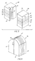
- substrates 10, 12 have quarter core structures 14,16,18,20 deposited thereon.
- the quarter core 14 consists of thin magnetic laminations 22,24, quarter core 16 of thin magnetic laminations 26,28, quarter core 18 of thin magnetic laminations 30, 32 and quarter core 20 of thin magnetic laminations 34,36.
- the laminations (for example, 22,24) are deposited by sputtering, or by other deposition means known in the art, from a magnetic material such as FeRuGaSi in a manner known in the art, and the individual laminations are electrically insulated from its adjacent neighbor by means of thin layers 38,40,42,44 of deposited SiO2 or similar insulating material.
- the substrates 10, 12 are overlaid on each other and the quarter core structure 14 is bonded to that of quarter core structure 20, and the quarter core structure 16 is bonded to quarter core structure 18.
- the surfaces of laminations 24,28,32,36 are deposited with thin bonding layers of Au, 46,48,50,52 respectively.
- the substrates 10,12 are then placed on each other with the quarter core structures 16,18 and 14,20 in geometrical registration and the temperature set between 200-400 degrees C to effect the bonding of the laminations by diffusion of the Au layer 46 into layer 52, and layer 48 into layer 50. After bonding the resultant structure of bonded laminations and substrates is lapped down to lines 54, 56.
- half core 68 consists of the substrate portions 10', 12' sandwiching the head laminations 26',28',32',30', which have previously been diffusion bonded along the bond line 51'.
- the half core 66 consists of substrate portions 10'',12'' sandwiching the head laminations 22',24'34'36' previously diffusion bonded along the line 51''.
- An Au bonding layer 70 is deposited on the face of the half core structure 68, and Au layers 72,74 are deposited on the face of the half core 66.
- the half cores 66,68 are placed with the bonding layers 70 and 72,74 in contact, pressure applied and the temperature raised to 200-400 degrees C to effect diffusion bonding of the half cores 66,68.
- This second bonding step not only joins the two half cores 66,68 but also establishes the gap width 78 (Fig. 4) of the magnetic head.
- the bonded head structure is then contoured to provide the head/tape interface resulting in the completed head structure 76 as seen in Fig. 4.
Landscapes
- Engineering & Computer Science (AREA)
- Manufacturing & Machinery (AREA)
- Magnetic Heads (AREA)
Applications Claiming Priority (2)
| Application Number | Priority Date | Filing Date | Title |
|---|---|---|---|
| US26835494A | 1994-06-30 | 1994-06-30 | |
| US268354 | 2002-10-10 |
Publications (1)
| Publication Number | Publication Date |
|---|---|
| EP0694908A1 true EP0694908A1 (fr) | 1996-01-31 |
Family
ID=23022604
Family Applications (1)
| Application Number | Title | Priority Date | Filing Date |
|---|---|---|---|
| EP95109991A Withdrawn EP0694908A1 (fr) | 1994-06-30 | 1995-06-24 | Tête magnétique avec entrefer lié par diffusion et noyau feuilleté par diffusion |
Country Status (2)
| Country | Link |
|---|---|
| EP (1) | EP0694908A1 (fr) |
| JP (1) | JPH0845014A (fr) |
Citations (6)
| Publication number | Priority date | Publication date | Assignee | Title |
|---|---|---|---|---|
| US4025379A (en) * | 1973-05-03 | 1977-05-24 | Whetstone Clayton N | Method of making laminated magnetic material |
| EP0220012A2 (fr) * | 1985-10-07 | 1987-04-29 | Nippon Mining Company Limited | Film magnétique laminé, méthode de sa fabrication et tête magnétique contenant ce structure |
| CH668331A5 (en) * | 1985-11-11 | 1988-12-15 | Studer Willi Ag | Magnetic head core mfr. from stack of laminations - involves linear machining of patterns from adhesively bonded and rolled sandwich of permeable and non-permeable layers |
| US5162960A (en) | 1989-03-20 | 1992-11-10 | Sony Corporation | Magnetic head with improved core bonding |
| US5208971A (en) * | 1990-05-17 | 1993-05-11 | Matsushita Electric Industrial Co., Ltd. | Process of manufacturing a magnetic head |
| JPH064822A (ja) * | 1992-04-24 | 1994-01-14 | Sony Corp | 磁気ヘッド及びその製造方法 |
-
1995
- 1995-06-24 EP EP95109991A patent/EP0694908A1/fr not_active Withdrawn
- 1995-06-30 JP JP16550095A patent/JPH0845014A/ja active Pending
Patent Citations (6)
| Publication number | Priority date | Publication date | Assignee | Title |
|---|---|---|---|---|
| US4025379A (en) * | 1973-05-03 | 1977-05-24 | Whetstone Clayton N | Method of making laminated magnetic material |
| EP0220012A2 (fr) * | 1985-10-07 | 1987-04-29 | Nippon Mining Company Limited | Film magnétique laminé, méthode de sa fabrication et tête magnétique contenant ce structure |
| CH668331A5 (en) * | 1985-11-11 | 1988-12-15 | Studer Willi Ag | Magnetic head core mfr. from stack of laminations - involves linear machining of patterns from adhesively bonded and rolled sandwich of permeable and non-permeable layers |
| US5162960A (en) | 1989-03-20 | 1992-11-10 | Sony Corporation | Magnetic head with improved core bonding |
| US5208971A (en) * | 1990-05-17 | 1993-05-11 | Matsushita Electric Industrial Co., Ltd. | Process of manufacturing a magnetic head |
| JPH064822A (ja) * | 1992-04-24 | 1994-01-14 | Sony Corp | 磁気ヘッド及びその製造方法 |
Non-Patent Citations (1)
| Title |
|---|
| PATENT ABSTRACTS OF JAPAN vol. 018, no. 208 (P - 1725) 13 April 1994 (1994-04-13) * |
Also Published As
| Publication number | Publication date |
|---|---|
| JPH0845014A (ja) | 1996-02-16 |
Similar Documents
| Publication | Publication Date | Title |
|---|---|---|
| JPH0258714A (ja) | 磁気ヘッド | |
| JP2874787B2 (ja) | 合金磁性薄膜積層体の製造方法 | |
| US4788762A (en) | Method of manufacturing a magnetic head for a video magnetic tape apparatus | |
| JP2618860B2 (ja) | 磁気ヘッド及びその製造方法 | |
| JPH0845014A (ja) | 磁気ヘッドおよびその製造方法 | |
| JPS61217921A (ja) | 薄膜ビデオヘツド | |
| JP2889072B2 (ja) | 薄膜積層磁気ヘッドチップ及びその製法 | |
| JPH06139515A (ja) | 積層型磁気ヘッドの製造方法 | |
| JP2810820B2 (ja) | 磁気ヘッド及び磁気ヘッドの製造方法 | |
| JPS61131209A (ja) | 磁気ヘツド | |
| JPH06111224A (ja) | 磁気ヘッド及びその製造方法 | |
| JPS61123006A (ja) | 磁気ヘツド | |
| JPS6038714A (ja) | 薄膜ビデオヘッド及びその製造方法 | |
| JPH0721512A (ja) | 磁気ヘッドの製造方法 | |
| JPH0792900B2 (ja) | 磁気ヘツドの製造法 | |
| JPS618710A (ja) | 磁気ヘツドの製造方法 | |
| JPH07182616A (ja) | 磁気ヘッドの製造方法 | |
| JPH06325313A (ja) | 磁気ヘッド及びその製造方法 | |
| JPH05159226A (ja) | 磁気ヘッドおよびその製造方法 | |
| JPS59142720A (ja) | 磁気ヘツドコア及びその製造方法 | |
| JPS62273613A (ja) | 磁気ヘツドの製造方法 | |
| JPS60195710A (ja) | 磁気ヘツドの製造方法 | |
| JPS5952419A (ja) | 薄膜磁気ヘツド | |
| JPH0773407A (ja) | 磁気ヘッドチップの製造方法 | |
| JPS63121109A (ja) | 薄膜磁気ヘツド |
Legal Events
| Date | Code | Title | Description |
|---|---|---|---|
| PUAI | Public reference made under article 153(3) epc to a published international application that has entered the european phase |
Free format text: ORIGINAL CODE: 0009012 |
|
| AK | Designated contracting states |
Kind code of ref document: A1 Designated state(s): DE FR GB |
|
| 17P | Request for examination filed |
Effective date: 19960629 |
|
| GRAG | Despatch of communication of intention to grant |
Free format text: ORIGINAL CODE: EPIDOS AGRA |
|
| 17Q | First examination report despatched |
Effective date: 19970127 |
|
| STAA | Information on the status of an ep patent application or granted ep patent |
Free format text: STATUS: THE APPLICATION HAS BEEN WITHDRAWN |
|
| 18W | Application withdrawn |
Withdrawal date: 19970502 |