EP0696096A1 - Appareil de pose ou de transport - Google Patents
Appareil de pose ou de transport Download PDFInfo
- Publication number
- EP0696096A1 EP0696096A1 EP95907828A EP95907828A EP0696096A1 EP 0696096 A1 EP0696096 A1 EP 0696096A1 EP 95907828 A EP95907828 A EP 95907828A EP 95907828 A EP95907828 A EP 95907828A EP 0696096 A1 EP0696096 A1 EP 0696096A1
- Authority
- EP
- European Patent Office
- Prior art keywords
- pipe
- slit
- moving body
- cable
- laying
- Prior art date
- Legal status (The legal status is an assumption and is not a legal conclusion. Google has not performed a legal analysis and makes no representation as to the accuracy of the status listed.)
- Granted
Links
Images




Classifications
-
- H—ELECTRICITY
- H02—GENERATION; CONVERSION OR DISTRIBUTION OF ELECTRIC POWER
- H02G—INSTALLATION OF ELECTRIC CABLES OR LINES, OR OF COMBINED OPTICAL AND ELECTRIC CABLES OR LINES
- H02G1/00—Methods or apparatus specially adapted for installing, maintaining, repairing or dismantling electric cables or lines
- H02G1/06—Methods or apparatus specially adapted for installing, maintaining, repairing or dismantling electric cables or lines for laying cables, e.g. laying apparatus on vehicle
- H02G1/08—Methods or apparatus specially adapted for installing, maintaining, repairing or dismantling electric cables or lines for laying cables, e.g. laying apparatus on vehicle through tubing or conduit, e.g. rod or draw wire for pushing or pulling
-
- H—ELECTRICITY
- H02—GENERATION; CONVERSION OR DISTRIBUTION OF ELECTRIC POWER
- H02G—INSTALLATION OF ELECTRIC CABLES OR LINES, OR OF COMBINED OPTICAL AND ELECTRIC CABLES OR LINES
- H02G1/00—Methods or apparatus specially adapted for installing, maintaining, repairing or dismantling electric cables or lines
- H02G1/06—Methods or apparatus specially adapted for installing, maintaining, repairing or dismantling electric cables or lines for laying cables, e.g. laying apparatus on vehicle
-
- G—PHYSICS
- G02—OPTICS
- G02B—OPTICAL ELEMENTS, SYSTEMS OR APPARATUS
- G02B6/00—Light guides; Structural details of arrangements comprising light guides and other optical elements, e.g. couplings
- G02B6/46—Processes or apparatus adapted for installing or repairing optical fibres or optical cables
- G02B6/50—Underground or underwater installation; Installation through tubing, conduits or ducts
- G02B6/502—Installation methods in fluid conducts, e.g. pipelines
-
- H—ELECTRICITY
- H02—GENERATION; CONVERSION OR DISTRIBUTION OF ELECTRIC POWER
- H02G—INSTALLATION OF ELECTRIC CABLES OR LINES, OR OF COMBINED OPTICAL AND ELECTRIC CABLES OR LINES
- H02G1/00—Methods or apparatus specially adapted for installing, maintaining, repairing or dismantling electric cables or lines
- H02G1/06—Methods or apparatus specially adapted for installing, maintaining, repairing or dismantling electric cables or lines for laying cables, e.g. laying apparatus on vehicle
- H02G1/08—Methods or apparatus specially adapted for installing, maintaining, repairing or dismantling electric cables or lines for laying cables, e.g. laying apparatus on vehicle through tubing or conduit, e.g. rod or draw wire for pushing or pulling
- H02G1/086—Methods or apparatus specially adapted for installing, maintaining, repairing or dismantling electric cables or lines for laying cables, e.g. laying apparatus on vehicle through tubing or conduit, e.g. rod or draw wire for pushing or pulling using fluid as pulling means, e.g. liquid, pressurised gas or suction means
Definitions
- the present invention relates to an apparatus for laying a material to be laid such as a cable outside a pipe along the pipe, for transporting an object at a place where an inflammable substance such as an organic solvent and the like is treated and an electric motor cannot be used. More in detail, it relates to a laying or transporting apparatus of a cable or an object connected to a moving body by propelling the moving body in the pipe by means of a compressed air or a pulling wire.
- a cable etc. is entered into a laid pipe, and a compressed air or a bamboo is passed therethrough, so that the cable etc. is laid in the pipe.
- a heavy cable such as a power electric wire and a control wire cannot be laid between the electric room in the construction and the electric equipments on the site.
- a number of operators are distributed previously between the electric room and the electric equipments then the cable is transferred by the hands of the operators.
- the operators are distributed every about 20 meters, then the first operator pulls the cable while taking a cable head on a leading end of the cable wound around a cable drum and transfers the cable head to the next operator which is distributed about 20 meters away, and the next operator pulls the cable while taking the cable head in the same way, and transfers it to further next operator.
- the cable head passes through the laying place and the cable has been finished to be pulled to the destination, the cable is transferred to a predetermined position of racks and the like by the hands of all of the operators in time to the shout of the leader of the operators.
- a conventional laying operation requires a number of persons, also requires a long time of operation.
- a foothold is established, and then the operators must move on footing boards from a starting point to a terminal point of the cable, so that there are problems that the efficiency of the laying operation is poor, and that it is dangerous.
- the object is laid on a complicated route which is bent up and down, right and left, there are many cases that not only the cable but also the equipments in the vicinity of the route are damaged.
- an object of the present invention to provide a laying or transporting apparatus in which a smaller number of persons are needed for the laying or transporting operation, and the laying or transporting time can be reduced compared with that in the prior art apparatus.
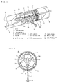
- a laying or transporting apparatus which utilizes a compressed air, according to the present invention, comprises a pipe 9 having a slit 6 along a longitudinal direction thereof throughout a full length thereof, a moving body 23 inserted into the pipe 9 and being movable in the pipe 9 by means of a compressed air fed into the pipe 9, and a connection member 1 connected to the moving body 23 in the pipe 9 at a base end thereof, passing through the slit 6 and positioned outside the pipe 9 at a leading end thereof to which a material 15 to be laid (Fig. 8) such as a cable or an object is connected.
- a sealing wire rod 8 which can blockade the slit 6 is arranged in the pipe 9 throughout the full length of the pipe, and a guide groove 7 for guiding the sealing wire rod 8 so as to blockade the slit 6 at the time of movement of the moving body is disposed on the moving body 23.
- the moving body 23 is inserted into the pipe 9, the connection member 1 is taken out of the slit 6, and the material 15 to be laid is connected to the leading end thereof. After that, the compressed air is introduced into the pipe 9, and then the moving body 23 is propelled, simultaneously the material 15 to be laid outside the pipe 9 is pulled and laid.
- a laying or transporting apparatus which utilizes a pulling wire, according to the present invention, comprises a pipe 49 having a slit 46 along a longitudinal direction thereof throughout a full length thereof, a moving body 63 inserted into the pipe 49 and being movable in the pipe 49, a connection member 41 connected to the moving body 63 in the pipe 49 at a base end thereof, passing through the slit 46 and positioned outside the pipe 49 at a leading end thereof to which a material 55 to be laid (Fig. 15) or an object is connected, and a first pulling wire 51 arranged along the pipe 49 from a terminal end of the pipe 49 and connected to the connection member 41.
- the apparatus comprises a second pulling wire 52 arranged along the pipe 49 from a starting end of the pipe 49 and connected to the moving body 63 in case of laying or transporting a plurality of materials to be laid or the objects.
- the moving body 63 is inserted into the pipe 49 from the starting point of the pipe 49, the connection member 41 is taken out of the pipe through the slit 46. After that, the first pulling wire 51 is connected to the connection member 41 and further the material 55 to be laid is connected to the leading end thereof.
- the moving body 63 is propelled, simultaneously the material 55 to be laid at an outside of the pipe is pulled, then the object is laid from the starting end to the terminal end of the pipe 49.
- the second material to be laid (not shown in the Figures) is laid, the second pulling wire 52 is pulled and the moving body 63 is returned to the starting end of the pipe 49, and then the second material to be laid is laid similarly by pulling the first pulling wire 51.
- a pipe 9 of the first embodiment is a pipe used for jet-pulling propulsion, is made of stainless steel and has a slit 6 along a longitudinal direction of the pipe throughout the full length of the pipe.
- a moving body 23 which is movable by a compressed air (jet-pulling) fed into the pipe is inserted into the pipe 9.
- a sealing wire rod 8 comprising a rubber wire having a circular section which can blockade the slit 6 is arranged in the pipe 9 throughout the full length of the pipe.
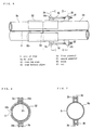
- the pipes 9 are connected in plural corresponding to the laying distance of the cable. As shown in Figs. 5 to 7, a leading end of the pipe 9a to be connected is connected to a base end of a connecting pipe 9b through a coupling pipe 32.
- the coupling pipe 32 is adapted to blockade seams 33 of both of the pipes 9a, 9b while remaining the slits 6 of the pipe 9a to be connected and the connecting pipe 9b.
- the coupling pipe 32 has a slit 32a having a width wider than that of the slit 6, throughout the full length of the pipe.
- One end of the coupling pipe 32 is welded to the base end of the pipe 9a to be connected in such a manner that the slit 6 is positioned at a center of the slit 32a, and a pair of first pedestals 34 are disposed on an outer face of the other end of the coupling pipe 32. Also, a pair of second pedestals 35 are disposed on an outer face of the leading end of the connecting pipe 9b.
- the pedestals 34, 35 each is formed in U-like shape, and welded to the outer face of the pipe.
- a pin 34a is disposed on the first pedestals 34 in a direction perpendicular to the pipe, a base end of a screw 36 is attached pivotably to the pin 34a.
- the screw 36 has a length through which a leading end thereof reaches the second pedestals 35 in a state that the base end of the pipe 9a and the leading end of the pipe 9b are connected to each other.
- the connecting pipe 9b is inserted into an open end of the coupling pipe 32 welded to the pipe 9a to be connected.
- the leading end of the screw 36 is entered between the second pedestals 35 in a state that both of the pipes 9a, 9b are connected to each other, then the screw 36 is disposed on both of the pedestals 34, 35, and then the nuts 37 are screwed. Both of the pipes 9a, 9b are fitted intimately by fastening the nut 37, and the gap is eliminated in the slit 33.
- a pair of the second pedestals 35 may be disposed on an outer face of the other end of the coupling pipe 32, a pair of the first pedestals 34 to which the base end of the screw 36 is attached pivotably may be disposed on the outer face of the leading end of the connecting pipe 9b.
- the moving body 23 has a center shaft 29 which coincides with a center of the pipe at an axis thereof.
- a ring 5 is fixed to a leading end of the center shaft 29, a number of bearing cases 2a are fixed to a center of the center shaft 29, and a sealing portion 26 is fixed to a base end of the center shaft 29.
- the ring 5 aims to pull a sealing wire rod 8 into the pipe 9 after the installing of the pipe 9.
- the bearing cases 2a are arranged radially in rows of three in a center shaft direction at equi-angular distances of 120° with the center shaft 29 as a center, and total 9 pieces, 3 pieces per each row, are provided.
- Bearing balls 2b which can roll on an inner face of the pipe are contained in the bearing cases 2a.
- the sealing portion 26 has a plurality of synthetic rubbers 3 and sponges 4 each having an outer diameter corresponding to an inner diameter of the pipe 9 to form a composite plate, and is constituted by arranging steel plates 12 and screwing the nuts 10b to the bolts 10a penetrating through the composite plate. Thereby, the sealing portion 26 contacts to the inner face of the pipe 9 so as to maintain the gas-tight.
- a guiding groove 7 for guiding the wire rod formed in the longitudinal direction of the pipe 9 is formed on one part of the sealing portion 26.
- the guiding groove 7 has a width of an outer diameter of the sealing wire rod 8, and the sealing wire rod 8 is inserted into the guiding groove 7.
- Two wire retaining rings 11 are fixed to a center of the center shaft 29 so as to be spaced apart from each other.
- a wire 1 as the connection member is passed through two of the rings 11.
- the wire 1 extends to an outside of the pipe 9 through the slit 8.
- a ring 1a for a connection with a cable head 30 ( Fig. 8) is attached to the leading end of the wire 1.
- a number of guide rollers 24 are attached to a cable laying rack 13 through an attaching tool 16 at intervals of about 2 meters from a starting point to a terminal point of the cable laying.
- the guide roller 24 aims to pull the cable with a smaller resistance force, and comprises a pair of swingable horizontal rollers 24a and a pair of vertical rollers 24b spaced apart from each other.
- the horizontal rollers 24a and the vertical rollers 24b are adapted to rotate freely, respectively.
- a number of pipes 9 are attached on the starting point to the terminal point of the cable laying through pipe holders 17 and attaching pieces 16 along the rack 13. Both of the pipes are connected to each other by the above mentioned coupling pipe 32. On this occasion, all of the pipes 9 are fitted in such a manner that the slits 6 are positioned at the lowermost position with respect to the section of the pipe as shown in Figs. 2 to 4.
- the compressor 20 and the drum 18 around which the cable is wound are arranged in the vicinity of the base end of the pipe 9.
- the air hose 21 is connected to the compressor 20 through the air adjusting valve 19.
- the moving body 23 is inserted into the pipe 9 from the base end of the pipe 9 again, and the sealing wire rod 8 is fitted into the guide groove 7 and the ring 1a of the leading end of the wire 1 is previously taken out of the slit 6.
- the leading end of the air hose 21 is connected to the base end of the pipe 9 through the coupling piece 22.
- the cable 15 is an electric cable.
- the wire 1 pulls the cable 15 through the cable head 30. That is, the wire 1 retained on the wire retaining ring 11 of the center shaft 29 shifts the sealing wire rod 8 from the slit 6, and then advances along a center of the slit 6. After the wire 1 passes therethrough, the guide groove 7 guides the sealing wire rod 8 toward the slit 6, and the sealing wire rod 8 contacts closely onto the slit 6.
- the cable 15 is pulled, the cable 15 is drawn out of the drum 18 and laid on the guide rollers 24 with a small resistance force by the guide rollers 24. On this occasion, the drum 18 is rotated by the hand of the operator so as not to add the back tension onto the cable 15.
- the gastightness in the pipe 9 from the coupling piece 22 of the air hose 21 to the moving body 23 is increased, so that the compressed air does not leak outside the pipe.
- the moving body 23 moves, the pressure of the air is maintained and the moving body 23 advances smoothly.
- the moving body 23 is accelerated by opening the air adjusting valve 19 gradually, then the cable 15 is pulled to the destination.
- the operator on the end informs the operator on the start by the communicating means such as the telephone, then the air adjusting valve 19 is closed.
- Figs. 9 and 10 show the second embodiment according to the present invention.
- the same reference numerals as the Figs. 1 to 4 and Fig. 8 represent the same components.
- the characteristic feature in this embodiment resides in that the deflecting piece 25 is attached on the intermediate location of the wire 1 at the outside of the pipe 9.
- the deflecting piece 25 comprises a small pipe made of metal, and a base end of the small pipe is formed so as to be curved outward the guide rollers 24 as shown in Fig. 9.
- the deflecting piece 25 is attached to a channel 25a of U-like in section which is disposed on the intermediate location of the wire 1.
- Reference numeral 14 denotes an already laid cable, and 15 is a cable to be laid newly.
- the horizontal rollers 24a do not rotate, so that the pulling resistance of the second cable 15 to be laid next becomes large. Therefore, after the pipe 9 is held by the holding plate 28, first the already laid cable 14 is inserted through the deflecting piece 25, next, the cable head 30 of the cable 15 to be laid newly is locked on the leading end of the wire 1 similarly to the above mentioned embodiment, and the compressed air is introduced into the pipe 9 similarly to the above mentioned embodiment.
- the moving body 23 is propelled due to the compressed air, first the already laid cable 14 is disengaged from the guide rollers 24 by the deflecting piece 25 and laid directly on the rack 13, so that the guide rollers 24 turn out to be capable of rotating freely. In this state, next, a new cable 15 is laid on the guide rollers 24.
- the cable 15 is locked on the deflecting piece 25, and laid in the same way.
- Fig. 11 shows the third embodiment.
- the same reference numerals as those of Fig. 4 represent the same components.
- the characteristic feature of this embodiment resides in that the slot 6 has a width corresponding to an outer diameter of the sealing wire rods 8, and that a slit covering plate 31 which narrows the width of the slot 6 is welded to an outer face of the pipe 9.
- the plate 31 is welded thereto from both sides of the slit 6 throughout the full length of the plate 9.
- Fig. 12 shows a fourth embodiment.
- the same reference numerals as those of Fig. 4 represent the same components.
- the characteristic feature of this embodiment resides in that a locking portion 8a which is locked on the slit 6 is disposed on the sealing wire rod 8.
- This locking portion 8a is flat rubber which is L-like in section, and formed integrally at the time of extrusion-molding of the wire rod 8 made of rubber which is circle in section.
- the locking portion 8a is locked on one end edge of the slit 6, so that the sealing wire rod 8 turns out not to be separated from the slit 6 even if the locking portion 8a serves as an anchor and then the pipe 9 is curved.
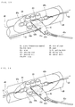
- Fig. 13 and Fig. 15 show a laying apparatus which utilizes the pulling wire of a fifth embodiment.
- the pipe 49 of the fifth embodiment is made of plastic, and has a slit 46 in the longitudinal direction throughout the full length of the pipe similarly to the pipe 9 of the first embodiment.
- a moving body 63 which is movable in the pipe is inserted inside the pipe 49.
- the moving body 63 has a center shaft 69 which coincides with a center of the pipe at a center axis thereof. Rings 45a and 45b are fixed to both ends of the center shaft 69, and a number of bearing cases 42a are fixed to the center of the center shaft 69.
- the bearing cases 42a are disposed radially in rows of three in a center shaft direction at equi-angular distances of 120° with the center shaft 69 as a center, and total 9 pieces, 3 pieces per each row, are provided.
- Bearing balls 42b which can roll on an inner face of the pipe are contained in the bearing cases 42a.
- a base end of a metal plate 41 which is a connection member is welded to the center of the center shaft 69.
- the plate 41 extends outside the pipe 49 through the slit 46.
- Holes 41a and 41b are disposed on a center and a leading end of the plate 41 outside the pipe.
- the hole 41a aims to hang a first pulling wire 51 comprising a fishing line or a thin metal wire
- the hole 41b aims to hang a wire 41c for connecting a cable head 70 (Fig. 15).
- a ring 45b in the pipe aims to hang a second pulling wire 52 comprising a fishing line or a thin metal wire.
- the first pulling wire 51 is wired along the pipe 49 from the terminal end of the pipe 49 which is the end of the cable laying
- the second pulling wire 52 is wired in the pipe from the start end of the pipe 49 which is the starting point of the cable laying.
- a number of guide rollers 64 are attached at regular intervals to a rack 53 which lays the cable similarly to the first embodiment.
- the pipe 49 is laid along the rack 53 from the starting point to the terminal point of the cable laying through the pipe holders and attaching pieces in such a manner that the slits 46 thereof is positioned at the lowermost in the direction of the pipe.
- a reel 71 of the second pulling wire 52 is disposed on a base 72 in the vicinity of the start end of the pipe 49, and also a reel 73 of the first pulling wire 51 is disposed on a base 73 in the vicinity of the terminal end of the pipe 49.
- a leading end of the pulling wire 52 drawn out of the reel 71 is hung on the ring 45b of the moving body 63, and the moving body 63 is inserted thereto from the start end of the pipe 49.
- the plate 41 is previously taken out of the slit 46.
- the leading end of the pulling wire 51 drawn out of the reel 73 is hung on the hole 41a of the plate 41, then a cable head 70 of the cable 55 is connected to the hole 41b of the plate 41 through the wire 41c.
- An operator 77 winds the pulling wire 51 on the reel 73 by rotating a handle 73a, then the moving body 63 is propelled by the pulling wire 51. Thereby, the plate 41 pulls the cable 55 through the cable head 70. The cable 55 is drawn out of a drum 58 arranged in the vicinity of the start end of the pipe 49.
- the operator 76 pulls the pulling wire 52 on the reel 71 by rotating the handle 71a to move the moving body to the start end of the pipe 49 again.
- the second wire is laid by connecting a new cable head to the wire 41c similarly to the first cable.
- Fig. 14 shows a laying apparatus which utilizes the pulling wire of the sixth embodiment.
- the characteristic construction in this example resides in that the first pulling wire 51 is hung on the wing 45a on the leading end of the center shaft 69 instead of the hole 41a of the plate 41. Thereby, since the pulling wire 51 is positioned in the pipe during pulling, there can be decreased the abrasion or the contamination of the pulling wire 51.
- the operator takes the plate 41 going out of the slit 46 by the hand to move the moving body 63 upto the terminal end of the pipe 49.
- the pulling wire 51 is hung on the ring 45a and the reel 71 (Fig. 15) is rotated, then the moving body 63 is returned to the start end of the pipe 49.
- the cable head 70 is connected to the plate 41.
- the cable is laid by rotating the reel 73.
- connection member may be a metal plate having a thickness which can pass through the slit, as shown in the fifth embodiment.
- the apparatus for laying the electric wire is explained in the first to the sixth embodiments, the present invention is not limited thereto, and can be used for the laying apparatus for the other pulling cable and the wire rod and the like. Also, the present invention can be applied for an apparatus for carrying by the compressed air an object at a place where an inflammable substance such as an organic solvent is treated and an electric motor cannot be used.
- the second pulling wire 52 of the fifth and the sixth embodiments may be hung on the plate 41, and the pipes of the fifth and the sixth embodiments may be made of stainless steel.
- the object can be moved over a wide range, an a plurality of the objects can be carried at any intervals.
- the object can be moved on the complicated route even the place where the rails cannot be equipped, so that the use is wide extremely.
- the moving body is inserted into the pipe, the wire connected to the moving body is taking out of the pipe, the material to be laid and the object is connected to the leading end of the wire, the moving body is propelled by utilizing the compressed air or the pulling wire, and the material to be laid or the object outside of the pipe is laid or carried along the pipe. Accordingly, the smaller number of persons can carry out the laying or transporting operation, and can reduce the laying or transporting time sharply compared with that in the prior art apparatuses.
- the operation can be efficiently and safely ensured even if the course is located at the elevated spot and the complicated place.
- the laying or transporting apparatus according to the present invention is useful to lay the cable, or transports an object at a place where an inflammable substance such as an organic solvent is treated and an electric motor cannot be used.
Landscapes
- Physics & Mathematics (AREA)
- General Physics & Mathematics (AREA)
- Optics & Photonics (AREA)
- Electric Cable Installation (AREA)
- Laying Of Electric Cables Or Lines Outside (AREA)
- Light Guides In General And Applications Therefor (AREA)
Applications Claiming Priority (5)
| Application Number | Priority Date | Filing Date | Title |
|---|---|---|---|
| JP4300494 | 1994-02-04 | ||
| JP43004/94 | 1994-02-04 | ||
| JP573495 | 1995-01-18 | ||
| JP5734/95 | 1995-01-18 | ||
| PCT/JP1995/000137 WO1995021482A1 (fr) | 1994-02-04 | 1995-01-31 | Appareil de pose ou de transport |
Publications (3)
| Publication Number | Publication Date |
|---|---|
| EP0696096A1 true EP0696096A1 (fr) | 1996-02-07 |
| EP0696096A4 EP0696096A4 (fr) | 1996-05-15 |
| EP0696096B1 EP0696096B1 (fr) | 1998-09-09 |
Family
ID=26339733
Family Applications (1)
| Application Number | Title | Priority Date | Filing Date |
|---|---|---|---|
| EP95907828A Expired - Lifetime EP0696096B1 (fr) | 1994-02-04 | 1995-01-31 | Appareil de pose ou de transport |
Country Status (8)
| Country | Link |
|---|---|
| US (1) | US5645268A (fr) |
| EP (1) | EP0696096B1 (fr) |
| KR (1) | KR100206516B1 (fr) |
| CN (1) | CN1077338C (fr) |
| CA (1) | CA2159833C (fr) |
| DE (1) | DE69504607T2 (fr) |
| TW (1) | TW278266B (fr) |
| WO (1) | WO1995021482A1 (fr) |
Families Citing this family (9)
| Publication number | Priority date | Publication date | Assignee | Title |
|---|---|---|---|---|
| JP2872166B2 (ja) * | 1996-11-29 | 1999-03-17 | 建一 今野 | 圧縮空気を利用したモニタカメラ搬送装置 |
| US6491475B1 (en) * | 1997-12-26 | 2002-12-10 | Mirai Kogyo Kabushiki Kaisha | Cable bed system utilizing drag route formers and layer device , and cable laying method using same |
| US6681711B2 (en) | 2001-07-26 | 2004-01-27 | American Systems Corporation | System for deploying cable |
| KR100622458B1 (ko) | 2006-04-10 | 2006-09-12 | (주) 선엔지니어링종합건축사사무소 | 공동주택내의 지중케이블 설치용 케이블인입장치 |
| US9429257B2 (en) * | 2012-06-11 | 2016-08-30 | Abba Daddy Llc | Tangle-prevention sleeve for headphone/earphone wire |
| KR101562820B1 (ko) | 2014-01-21 | 2015-10-26 | 대우조선해양 주식회사 | 전선 포설 로봇의 제어 시스템 |
| US9808893B2 (en) | 2013-12-19 | 2017-11-07 | Walhonde Tools Inc. | Apparatus for aligning sections of pipe |
| CN107654030B (zh) * | 2017-09-26 | 2019-06-07 | 重庆雨帝建材有限公司 | 卷材铺张装置 |
| CN114123045B (zh) * | 2021-12-01 | 2022-11-11 | 贵州电网有限责任公司 | 一种穿管引线工具 |
Family Cites Families (17)
| Publication number | Priority date | Publication date | Assignee | Title |
|---|---|---|---|---|
| US356152A (en) * | 1887-01-18 | Conduit system for electric conductors | ||
| US458778A (en) * | 1891-09-01 | Electric subway | ||
| US524789A (en) * | 1894-08-21 | Electrical subway system | ||
| DE189054C (fr) * | ||||
| US521125A (en) * | 1894-06-05 | James j | ||
| CA469451A (fr) * | 1950-11-21 | Eugene Dufresne Joseph | Machines de tringlage | |
| US447350A (en) * | 1891-03-03 | Electrical subway | ||
| US2750151A (en) * | 1954-05-21 | 1956-06-12 | Max H Morris | Guide for an electrician's snake |
| DE7143360U (de) * | 1971-11-17 | 1972-03-09 | Abnox Ag | Einrichtung zum Einziehen von Hilfsseilen in Kabelrohre |
| US3869784A (en) * | 1973-10-03 | 1975-03-11 | Richard R Simpson | Tool for aligning articles |
| US4185809A (en) * | 1978-01-27 | 1980-01-29 | Nelson Jonnes | Method and apparatus for pulling lightweight cable |
| JPS5895909A (ja) * | 1981-12-02 | 1983-06-07 | 古河電気工業株式会社 | 電線の引込方法 |
| FR2599566B1 (fr) * | 1986-05-30 | 1988-09-02 | Morel Atel Electromec | Dispositif pneumatique pour la mise en place de cables dans un tube. |
| US5052608A (en) * | 1989-11-28 | 1991-10-01 | Mcclure Gary W | Pipe fitting tool |
| JPH0734615B2 (ja) * | 1989-12-30 | 1995-04-12 | 未来工業株式会社 | ケーブルの布設方法 |
| JP2567757B2 (ja) * | 1991-06-27 | 1996-12-25 | 未来工業株式会社 | 管内への配線・配管材の布設方法、これの布設装置及びこれに使用される配線・配管用の管 |
| JP3005696B2 (ja) * | 1991-06-28 | 2000-01-31 | 未来工業株式会社 | 配線・配管材布設用シュータ及び配線・配管材布設装置 |
-
1995
- 1995-01-31 EP EP95907828A patent/EP0696096B1/fr not_active Expired - Lifetime
- 1995-01-31 WO PCT/JP1995/000137 patent/WO1995021482A1/fr not_active Ceased
- 1995-01-31 KR KR1019950704300A patent/KR100206516B1/ko not_active Expired - Fee Related
- 1995-01-31 DE DE69504607T patent/DE69504607T2/de not_active Expired - Fee Related
- 1995-01-31 CN CN95190128A patent/CN1077338C/zh not_active Expired - Fee Related
- 1995-01-31 US US08/525,798 patent/US5645268A/en not_active Expired - Fee Related
- 1995-01-31 CA CA002159833A patent/CA2159833C/fr not_active Expired - Fee Related
- 1995-03-31 TW TW084103094A patent/TW278266B/zh active
Also Published As
| Publication number | Publication date |
|---|---|
| CA2159833C (fr) | 1999-01-19 |
| US5645268A (en) | 1997-07-08 |
| CN1077338C (zh) | 2002-01-02 |
| WO1995021482A1 (fr) | 1995-08-10 |
| DE69504607D1 (de) | 1998-10-15 |
| TW278266B (fr) | 1996-06-11 |
| KR100206516B1 (ko) | 1999-07-01 |
| EP0696096A4 (fr) | 1996-05-15 |
| CA2159833A1 (fr) | 1995-08-10 |
| EP0696096B1 (fr) | 1998-09-09 |
| CN1124069A (zh) | 1996-06-05 |
| DE69504607T2 (de) | 1999-05-06 |
| KR960702199A (ko) | 1996-03-28 |
Similar Documents
| Publication | Publication Date | Title |
|---|---|---|
| JP3046356B2 (ja) | 敷設又は運搬装置 | |
| US5645268A (en) | Laying and transporting apparatus | |
| US10995881B2 (en) | Conductor guide system | |
| US4951923A (en) | Electrical wire guide temporarily placed in an electrical wiring junction box to protect the insulation of electrical wires being guided and pulled into this box and through a conduit to the next junction box | |
| US6109561A (en) | Method and apparatus for cable dispensing and placement | |
| US2816734A (en) | Portable hose guide | |
| JP2652602B2 (ja) | 配線・配管材の懸吊部材及び配線・配管装置 | |
| US20180318892A1 (en) | Interlocking teeth for strengthening pinned connection between knuckle-jointed lance segments | |
| US12545560B2 (en) | Line roller assembly | |
| US4655432A (en) | Cable dispensing method | |
| US6726140B2 (en) | Take-up reel for flexible elongated members | |
| JPWO1995021482A1 (ja) | 敷設又は運搬装置 | |
| US4780025A (en) | Device for laying and suspending cables | |
| JP3354168B2 (ja) | 管・ケーブル等の布設具及び管・ケーブル等の布設装置 | |
| KR960016781B1 (ko) | 케이블 행거장치 | |
| CN219959963U (zh) | 一种临时使用电缆敷设支架 | |
| KR101672193B1 (ko) | 케이블 포설 장치 | |
| JPH02236079A (ja) | ケーブル保護管の敷設方法 | |
| JP3838698B2 (ja) | 圧縮空気を利用した敷設又は運搬装置 | |
| JP2001221367A (ja) | 管材布設装置および管材布設方法 | |
| JPH1014040A (ja) | ケーブル敷設用ガイド装置 | |
| CN119460888A (zh) | 一种发电设备用线缆排布装置 | |
| JPH0674016U (ja) | 延線ローラ | |
| JPH07172696A (ja) | 電線等の案内通過装置 | |
| JPH11230410A (ja) | 管路の布設方法 |
Legal Events
| Date | Code | Title | Description |
|---|---|---|---|
| PUAI | Public reference made under article 153(3) epc to a published international application that has entered the european phase |
Free format text: ORIGINAL CODE: 0009012 |
|
| AK | Designated contracting states |
Kind code of ref document: A1 Designated state(s): DE FR GB |
|
| 17P | Request for examination filed |
Effective date: 19960110 |
|
| A4 | Supplementary search report drawn up and despatched | ||
| AK | Designated contracting states |
Kind code of ref document: A4 Designated state(s): DE FR GB |
|
| RAP1 | Party data changed (applicant data changed or rights of an application transferred) |
Owner name: KONNO, KENICHI |
|
| RIN1 | Information on inventor provided before grant (corrected) |
Inventor name: KONNO, KENICHI |
|
| 17Q | First examination report despatched |
Effective date: 19970128 |
|
| GRAG | Despatch of communication of intention to grant |
Free format text: ORIGINAL CODE: EPIDOS AGRA |
|
| GRAG | Despatch of communication of intention to grant |
Free format text: ORIGINAL CODE: EPIDOS AGRA |
|
| GRAH | Despatch of communication of intention to grant a patent |
Free format text: ORIGINAL CODE: EPIDOS IGRA |
|
| GRAH | Despatch of communication of intention to grant a patent |
Free format text: ORIGINAL CODE: EPIDOS IGRA |
|
| GRAA | (expected) grant |
Free format text: ORIGINAL CODE: 0009210 |
|
| AK | Designated contracting states |
Kind code of ref document: B1 Designated state(s): DE FR GB |
|
| REF | Corresponds to: |
Ref document number: 69504607 Country of ref document: DE Date of ref document: 19981015 |
|
| ET | Fr: translation filed | ||
| PLBE | No opposition filed within time limit |
Free format text: ORIGINAL CODE: 0009261 |
|
| STAA | Information on the status of an ep patent application or granted ep patent |
Free format text: STATUS: NO OPPOSITION FILED WITHIN TIME LIMIT |
|
| 26N | No opposition filed | ||
| PGFP | Annual fee paid to national office [announced via postgrant information from national office to epo] |
Ref country code: GB Payment date: 20011214 Year of fee payment: 8 |
|
| PGFP | Annual fee paid to national office [announced via postgrant information from national office to epo] |
Ref country code: DE Payment date: 20011217 Year of fee payment: 8 |
|
| PGFP | Annual fee paid to national office [announced via postgrant information from national office to epo] |
Ref country code: FR Payment date: 20011226 Year of fee payment: 8 |
|
| REG | Reference to a national code |
Ref country code: GB Ref legal event code: IF02 |
|
| PG25 | Lapsed in a contracting state [announced via postgrant information from national office to epo] |
Ref country code: GB Free format text: LAPSE BECAUSE OF NON-PAYMENT OF DUE FEES Effective date: 20030131 |
|
| PG25 | Lapsed in a contracting state [announced via postgrant information from national office to epo] |
Ref country code: DE Free format text: LAPSE BECAUSE OF NON-PAYMENT OF DUE FEES Effective date: 20030801 |
|
| GBPC | Gb: european patent ceased through non-payment of renewal fee | ||
| PG25 | Lapsed in a contracting state [announced via postgrant information from national office to epo] |
Ref country code: FR Free format text: LAPSE BECAUSE OF NON-PAYMENT OF DUE FEES Effective date: 20030930 |
|
| REG | Reference to a national code |
Ref country code: FR Ref legal event code: ST |