EP0696100B1 - Machine électrique tournante - Google Patents
Machine électrique tournante Download PDFInfo
- Publication number
- EP0696100B1 EP0696100B1 EP95305414A EP95305414A EP0696100B1 EP 0696100 B1 EP0696100 B1 EP 0696100B1 EP 95305414 A EP95305414 A EP 95305414A EP 95305414 A EP95305414 A EP 95305414A EP 0696100 B1 EP0696100 B1 EP 0696100B1
- Authority
- EP
- European Patent Office
- Prior art keywords
- rotation shaft
- bearing
- sleeve bearing
- thrust bearing
- sleeve
- Prior art date
- Legal status (The legal status is an assumption and is not a legal conclusion. Google has not performed a legal analysis and makes no representation as to the accuracy of the status listed.)
- Expired - Lifetime
Links
- 230000005611 electricity Effects 0.000 claims description 7
- 230000003068 static effect Effects 0.000 claims description 7
- 239000002184 metal Substances 0.000 claims 1
- 229910001047 Hard ferrite Inorganic materials 0.000 description 2
- XEEYBQQBJWHFJM-UHFFFAOYSA-N Iron Chemical compound [Fe] XEEYBQQBJWHFJM-UHFFFAOYSA-N 0.000 description 2
- 239000012530 fluid Substances 0.000 description 2
- 238000000034 method Methods 0.000 description 2
- 229920001875 Ebonite Polymers 0.000 description 1
- 238000005219 brazing Methods 0.000 description 1
- 230000006866 deterioration Effects 0.000 description 1
- 238000007599 discharging Methods 0.000 description 1
- 230000000694 effects Effects 0.000 description 1
- 229910052742 iron Inorganic materials 0.000 description 1
- 239000002245 particle Substances 0.000 description 1
- 230000002093 peripheral effect Effects 0.000 description 1
- 238000004080 punching Methods 0.000 description 1
- 238000004513 sizing Methods 0.000 description 1
Images


Classifications
-
- H—ELECTRICITY
- H02—GENERATION; CONVERSION OR DISTRIBUTION OF ELECTRIC POWER
- H02K—DYNAMO-ELECTRIC MACHINES
- H02K5/00—Casings; Enclosures; Supports
- H02K5/04—Casings or enclosures characterised by the shape, form or construction thereof
- H02K5/16—Means for supporting bearings, e.g. insulating supports or means for fitting bearings in the bearing-shields
- H02K5/167—Means for supporting bearings, e.g. insulating supports or means for fitting bearings in the bearing-shields using sliding-contact or spherical cap bearings
- H02K5/1675—Means for supporting bearings, e.g. insulating supports or means for fitting bearings in the bearing-shields using sliding-contact or spherical cap bearings radially supporting the rotary shaft at only one end of the rotor
-
- F—MECHANICAL ENGINEERING; LIGHTING; HEATING; WEAPONS; BLASTING
- F16—ENGINEERING ELEMENTS AND UNITS; GENERAL MEASURES FOR PRODUCING AND MAINTAINING EFFECTIVE FUNCTIONING OF MACHINES OR INSTALLATIONS; THERMAL INSULATION IN GENERAL
- F16C—SHAFTS; FLEXIBLE SHAFTS; ELEMENTS OR CRANKSHAFT MECHANISMS; ROTARY BODIES OTHER THAN GEARING ELEMENTS; BEARINGS
- F16C17/00—Sliding-contact bearings for exclusively rotary movement
- F16C17/04—Sliding-contact bearings for exclusively rotary movement for axial load only
- F16C17/08—Sliding-contact bearings for exclusively rotary movement for axial load only for supporting the end face of a shaft or other member, e.g. footstep bearings
Definitions
- the present invention relates to a bearing apparatus in, particularly, a motor for a floppy disc drive device.
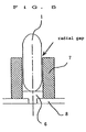
- a floppy disc drive device has been widely used for a computer external memory device, since it allows flexible replacements of floppy discs and easy treatment. Recently, there has been a tendency to down-sizing computers, and therefore, the floppy disc drive devices is included in microcomputers have come to follow this tendency. In addition, as the size of a floppy disc drive device is reduced, the motor for driving a floppy disc must be formed to have a small and thin size. Although conventional bearings for driving a floppy disc drive device have been of ball bearing type, bearings of the type as shown in FIG. 5 have been recently used for reasons as stated above.
- a rotation shaft 1 is supported by a sleeve bearing 7 and a thrust bearing 6, as shown in FIG. 5, and therefore, there is a small gap in the radial direction. So that, when an external force is applied to a rotor yoke or when a magnetic unbalance occurs, inclination of the rotation shaft 1 changes, As a result, read/write characteristics of the floppy disc drive device are deteriorated in some cases. Therefore, a concept of a dynamic pressure type bearing using a fluid such as an oil or the like has been proposed as a method of filling the radial gap.
- the rotation speed of floppy disc drive device drive motor is about 300 rpm, so that sufficient effects cannot be obtained by a dynamic pressure type bearing using a fluid like an oil.
- floppy disc drive device chassis is electrically isolated from the rotation shaft 1, so that it is not possible to form a circuit for discharging static electricity of a floppy disc, which is necessary for floppy disc drive device drive motor.
- the present invention has been made to improve drawbacks of a conventional apparatus as stated above, and an object of the present invention is to provide a bearing apparatus in an electrical rotating machine especially floppy disc drive device motor which has a simple structure, which ensures a sufficient rotational accuracy of a rotation shaft to prevent deterioration in read/write characteristics of floppy disc drive device, and which can discharge static electricity of an floppy disc.
- EP-A-0589514 discloses a rotating machine having a rotor and stator rotatable relatively to one another, the machine comprising a frame mounting a stator yoke which forms part of the stator; a cylindrical shaped sleeve mounted on the frame; a rotation shaft supporting the rotor and having a curve shaped end and a diameter which is smaller than the inside diameter of the sleeve bearing and rotatably supported in said sleeve bearing, and a thrust bearing supporting the curve shaped end of the rotation shaft and, according to the present invention, such a machine is characterised by the upper surface of the thrust bearing being shaped to provide a concave portion, which is offset from the centre line of the sleeve bearing, whereby the curve shaped end of the rotation shaft rests in the concave portion with the rotation shaft inclined to the centre line of, and in contact with, the sleeve bearing, the inclination being stabilised by magnetic attraction between the stator and the rotor; and by
- FIG. 1 is a cross-sectional view showing a first embodiment of the present invention.
- FIG. 2 is an enlarged view showing a bearing portion according to the first embodiment of the present invention.
- FIG. 3 is an enlarged view showing a bearing portion according to a second embodiment of the present invention.
- FIG. 4 is a cross-sectional view showing a part of an other embodiment.
- FIG. 5 is an enlarged view showing a bearing portion of a conventional motor.
- FIG.1 is a cross-sectional view of floppy disc drive device motor according to the present invention .
- reference 1 denotes a rotation shaft of a motor
- reference 2 denotes a rotor yoke.
- the rotor yoke 2 is formed in a disc-like shape by punching a permeable soft iron plate by press-processing, and a hole for allowing the rotation shaft 1 to penetrate is formed in the center of the yoke.
- the rotation shaft 1 is forcibly engaged in the hole, and thus, the rotor yoke 2 is finally fixed to the rotation shaft 1.
- floppy disc When the floppy disc drive device motor is incorporated in the floppy disc drive device, floppy disc is mounted on the upper surface of the rotor yoke 2, so that the floppy disc rotates as the rotor yoke 2 rotates.
- a magnet 3 formed of hard ferrite or hard rubber and hard ferrite particles mixed and kneaded there into is inside the peripheral portion of the rotor yoke 2. This magnet 3 is magnetized such that N- and S-poles alternately appears along the circumferential direction of the rotor yoke 2.
- Reference 4 denotes a stator coil
- reference 5 denotes a stator yoke.
- References 6, 7 and 8 respectively denote a thrust bearing, a sleeve bearing, and a motor frame. Further, the stator yoke 5 is fixed on the motor frame 8. A sleeve bearing 7 is installed in the center of the stator yoke 5, and the rotation shaft 1 is rotatably supported by the bearing 7, which will be described in more detail later.
- the stator yoke 5 is provided with a plurality of magnetic poles formed in a star-like arrangement, in the direction from the center towards the magnet 3.
- a stator coil 4 is wound near the tops of the star-like arrangement.
- FIG. 2 is an enlarged cross-sectional view showing a part of bearing portion (i.e., portion A shown in FIG. 1).
- a thrust bearing 6 is provided on the internal bottom surface of the sleeve bearing 7 having a sleeve shape whose bottom portion is fixed to the motor frame 8.
- a projection 6c is provided at the bottom portion of the thrust bearing 6, and this projection 6c is engaged in a hole formed in the motor frame.
- the end of the bottom portion of the rotation shaft 1 has a hemispheric shape.
- a conical projection 6a forming to the side thereof a concavity, is provided on the upper surface of the thrust bearing 6 at a deviated portion thereof, i.e., at a position offset from the center line of the sleeve bearing 7 indicated by one-dot-dashed line in the figure.
- the bottom portion of the rotation shaft 1 is formed in a hemispherical shape and the projection 6a is provided on the upper surface of the thrust bearing 6 at a portion offset from the center thereof,so that the rotation shaft 1 is inclined with a gap between the rotation shaft 1 and the sleeve bearing 7. Consequently, as shown in FIG. 2, the end of the bottom portion of the rotation shaft 1 is in contact with the thrust bearing 6, and the side wall of the rotation shaft 1 is in contact with the sleeve bearing 7.
- the rotation shaft thus attains three contact points and is stably supported by these contact points.
- FIG. 3 is a partial enlarged cross-sectional view showing another embodiment of the present invention.
- a conical concave portion 6b is formed in the upper surface of a thrust bearing 6, and the end of the bottom portion of this concave portion 6b is situated at a deviated portion, i.e., a position offset from the center line of the sleeve bearing 7 indicated by one-dot-dashed line.
- a deviated portion i.e., a position offset from the center line of the sleeve bearing 7 indicated by one-dot-dashed line.
- those portions which are common to the portions of FIG. 1 are referred to by the same reference symbols, and explanation thereof will be omitted herefrom.
- a concave portion 6b is formed at a deviated portion offset from the center line of the sleeve bearing 7, and therefore, the rotation shaft 1 is inclined.
- the rotation shaft 1 is in contact with the thrust and sleeve bearings 6 and 7 at three points and is stably supported by these contact points, so that the rotation shaft rotates stably.
- the thrust bearing 6 is press-fitted and fixed to the hole formed in the motor frame 8 when assembling the motor. Therefore, it is not possible to perform fine adjustment of the positional relationship between the thrust bearing and the rotation shaft after assembling the motor.
- an engagement part 6c is provided in the bottom portion of the thrust bearing 6 to constitute a rotation portion, as shown in FIGS. 2 and 3, and the thrust bearing 6 is rotatably installed on the motor frame 8 when assembling the motor. After assembling the motor, the rotational position of the thrust bearing 6 is adjusted with a screw driver when testing rotation of a floppy disc drive device motor, to attain the position where the rotation shaft 1 rotates at the highest stability.
- the thrust bearing 6 is fixed to the motor frame 8 by means of an adhering or brazing method or the like.
- a screw portion 9 is provided on an engaging surface of the thrust bearing 6 to be engaged with the motor frame 8, thereby to fix the thrust bearing 6 to the motor frame 8.
- the thrust bearing 6 can be fixed at a particular position to the motor frame 8. Therefore, the thrust bearing 6 is engaged in the motor frame 8 in such a manner in which the thrust bearing 6 does not rotate in relation to the motor frame 8.
- the cross-sections to be engaged with each other may be D- or I-shaped or may be of a convex shape or the like.
- the concave portion is provided on the upper surface of the thrust bearing at a position offset from the center line of the sleeve bearing and is thus deviated.
- the concave portion is provided on the center line, it is possible to form a stable contact portion between the bottom end of the rotation shaft and the thrust bearing as well as a stable contact portion between the side wall of the rotation shaft and the sleeve bearing, by canting the rotation shaft relatively to the sleeve bearing.
- the rotation shaft of a motor can be forcibly inclined with the rotation shaft and the sleeve bearing being kept in contact with each other. Therefore, it is possible to reduce deviation in inclination of the motor rotation shaft and to ensure electric conductance between the motor rotation shaft and the motor body.
Landscapes
- Engineering & Computer Science (AREA)
- General Engineering & Computer Science (AREA)
- Mechanical Engineering (AREA)
- Power Engineering (AREA)
- Motor Or Generator Frames (AREA)
- Rotational Drive Of Disk (AREA)
- Sliding-Contact Bearings (AREA)
Claims (7)
- Machine électrique rotative possédant un rotor et un stator pouvant tourner l'un par rapport à l'autre, la machine comprenant un cadre (8) portant un étrier de stator (5) faisant partie du stator; un palier à douille de forme cylindrique (7) monté sur le cadre (8); un arbre rotatif (1) supportant le rotor et possédant une extrémité de forme courbe et un diamètre qui est inférieur au diamètre interne du palier à douille (7) et supporté en rotation par ledit palier à douille (7), et un palier de butée (6) supportant l'extrémité de forme courbe de l'arbre rotatif (1);
caractérisée en ce que la surface supérieure du palier de butée (6) est conformée (6a, 6b) afin de constituer une partie concave qui est décalée de l'axe central du palier à douille (7), l'extrémité de forme courbe de l'arbre rotatif (1) reposant ainsi sur la partie concave, l'arbre rotatif étant incliné par rapport à l'axe central tout en étant en contact avec le palier à douille (7), l'inclinaison étant stabilisée par l'attraction magnétique entre le stator et le rotor; et par un trajet conducteur de l'électricité statique du rotor vers le cadre par l'intermédiaire de l'arbre rotatif (1) et du palier à douille (7). - Machine selon la revendication 1, caractérisée en ce qu'au moins un élément parmi le palier à douille (7) et le palier de butée (6) est constitué d'un métal et est raccordé, de façon électrique, au cadre (8).
- Machine selon la revendication 1 ou 2, caractérisée en ce que le palier de butée (6) peut tourner par rapport au palier à douille (7) afin de modifier la position angulaire de la partie concave.
- Machine selon l'une quelconque des revendications précédentes, caractérisée en ce que le palier de butée (6) est mobile dans la direction de poussée de l'arbre rotatif (7) afin de régler la position axiale de l'arbre rotatif.
- Machine selon la revendication 1 ou 2, caractérisée en ce que le palier de butée (6) est monté serré dans le palier à douille (7).
- Générateur selon l'une quelconque des revendications précédentes.
- Moteur selon l'une quelconque des revendications précédentes.
Applications Claiming Priority (2)
| Application Number | Priority Date | Filing Date | Title |
|---|---|---|---|
| JP06201340A JP3126880B2 (ja) | 1994-08-03 | 1994-08-03 | モータの軸受装置 |
| JP201340/94 | 1994-08-03 |
Publications (3)
| Publication Number | Publication Date |
|---|---|
| EP0696100A2 EP0696100A2 (fr) | 1996-02-07 |
| EP0696100A3 EP0696100A3 (fr) | 1996-12-18 |
| EP0696100B1 true EP0696100B1 (fr) | 1999-05-06 |
Family
ID=16439408
Family Applications (1)
| Application Number | Title | Priority Date | Filing Date |
|---|---|---|---|
| EP95305414A Expired - Lifetime EP0696100B1 (fr) | 1994-08-03 | 1995-08-02 | Machine électrique tournante |
Country Status (4)
| Country | Link |
|---|---|
| US (1) | US5762422A (fr) |
| EP (1) | EP0696100B1 (fr) |
| JP (1) | JP3126880B2 (fr) |
| DE (1) | DE69509455T2 (fr) |
Families Citing this family (3)
| Publication number | Priority date | Publication date | Assignee | Title |
|---|---|---|---|---|
| JP3208042B2 (ja) * | 1995-06-19 | 2001-09-10 | 株式会社三協精機製作所 | ディスク駆動用モータ |
| DE29721068U1 (de) * | 1997-11-27 | 1998-01-22 | Arturo Salice S.P.A., Novedrate, Como | Verbindungsbeschlag |
| JP2000004557A (ja) * | 1998-03-04 | 2000-01-07 | Seiko Instruments Inc | 空気動圧軸受を備えたスピンドルモ―タ及びこれを駆動源とする回転体装置 |
Family Cites Families (10)
| Publication number | Priority date | Publication date | Assignee | Title |
|---|---|---|---|---|
| US2246738A (en) * | 1941-06-24 | Means fob mounting gyros | ||
| GB375734A (en) * | 1931-09-25 | 1932-06-30 | Fritz Luethy | Improvements in spindle bearings for spinning frames and the like |
| FR2504620B1 (fr) * | 1981-04-27 | 1986-05-16 | Nippon Seiko Kk | Palier a fluide du type a pression dynamique |
| US4434448A (en) * | 1982-07-19 | 1984-02-28 | Westinghouse Electric Corp. | Non-contaminating transformer oil pump, static arrester, and control circuit |
| JPS61241518A (ja) * | 1985-04-19 | 1986-10-27 | Nippon Telegr & Teleph Corp <Ntt> | 油動圧すべり軸受 |
| US4856918A (en) * | 1987-03-10 | 1989-08-15 | Nippon Seiko Kabushiki Kaisha | Bearing device |
| JPH04145215A (ja) * | 1990-10-04 | 1992-05-19 | Canon Inc | 動圧軸受装置 |
| US5277499A (en) * | 1990-10-04 | 1994-01-11 | Canon Kabushiki Kaisha | Dynamic pressure bearing apparatus |
| JPH04277316A (ja) * | 1991-03-05 | 1992-10-02 | Matsushita Electric Ind Co Ltd | 流体軸受式回転ヘッドシリンダ |
| MY108842A (en) * | 1992-09-21 | 1996-11-30 | Koninklijke Philips Electronics Nv | Method of manufacturing a dynamic groove bearing, die suitable for use in such a method, and housing and bearing part manufactured by such a method; data storage unit provided with such a groove bearing, method of manufacturing a rotable scanning unit, and magnetic tape device provided with such a scanning unit |
-
1994
- 1994-08-03 JP JP06201340A patent/JP3126880B2/ja not_active Expired - Fee Related
-
1995
- 1995-08-02 EP EP95305414A patent/EP0696100B1/fr not_active Expired - Lifetime
- 1995-08-02 DE DE69509455T patent/DE69509455T2/de not_active Expired - Fee Related
-
1997
- 1997-06-26 US US08/882,961 patent/US5762422A/en not_active Expired - Fee Related
Also Published As
| Publication number | Publication date |
|---|---|
| EP0696100A2 (fr) | 1996-02-07 |
| DE69509455T2 (de) | 1999-10-28 |
| JPH0847202A (ja) | 1996-02-16 |
| US5762422A (en) | 1998-06-09 |
| JP3126880B2 (ja) | 2001-01-22 |
| DE69509455D1 (de) | 1999-06-10 |
| EP0696100A3 (fr) | 1996-12-18 |
Similar Documents
| Publication | Publication Date | Title |
|---|---|---|
| US4851731A (en) | Structure of a flat-type brushless DC motor | |
| US6844642B2 (en) | Spindle motor for hard disc drive with static charge discharging | |
| US5947608A (en) | Conical bearing apparatus used in a motor | |
| EP0696100B1 (fr) | Machine électrique tournante | |
| US5780947A (en) | Coreless motor | |
| JPH0729731Y2 (ja) | 回転電機 | |
| JP3424797B2 (ja) | スピンドルモータ、及びスピンドルモータを回転体の駆動源とした回転体装置 | |
| JP2005045868A (ja) | 振動モータ | |
| JP3229835B2 (ja) | モータの軸受装置およびこれを用いたモータ | |
| KR100224534B1 (ko) | 회전축이 고정된 스핀들 모터의 자기 베어링 | |
| JPH10174362A (ja) | 一軸受形ファンモータ | |
| JPH08182289A (ja) | 扁平型ブラシレスモータ | |
| JPH05288214A (ja) | スピンドルモータ | |
| US6519112B1 (en) | Liquid dynamic pressure bearing and spindle motor, hard-disk driving unit, and scanner motor using the bearing | |
| JP2596528Y2 (ja) | モータの空気ベアリングによるロータ支持構造及び回転軸支持構造 | |
| JP3986623B2 (ja) | 回転電機 | |
| KR19980069593A (ko) | 디지탈비디오디스크용 스핀들모터의 축지지장치 | |
| US5936809A (en) | Precision rotator | |
| KR100335235B1 (ko) | 디스크구동용스핀들모터 | |
| JP2002130256A (ja) | 動圧気体軸受装置 | |
| JP2005192385A (ja) | スピンドルモータ | |
| KR20000002777U (ko) | 모터에서의 누유 방지구조 | |
| JPH02304773A (ja) | ディスク装置のスピンドルアース構造及びスピンドル製造方法 | |
| JPH0965603A (ja) | モータ構造 | |
| JPH0750583Y2 (ja) | 流体軸受 |
Legal Events
| Date | Code | Title | Description |
|---|---|---|---|
| PUAI | Public reference made under article 153(3) epc to a published international application that has entered the european phase |
Free format text: ORIGINAL CODE: 0009012 |
|
| AK | Designated contracting states |
Kind code of ref document: A2 Designated state(s): DE GB |
|
| PUAL | Search report despatched |
Free format text: ORIGINAL CODE: 0009013 |
|
| AK | Designated contracting states |
Kind code of ref document: A3 Designated state(s): DE GB |
|
| 17P | Request for examination filed |
Effective date: 19970606 |
|
| 17Q | First examination report despatched |
Effective date: 19971216 |
|
| GRAG | Despatch of communication of intention to grant |
Free format text: ORIGINAL CODE: EPIDOS AGRA |
|
| GRAG | Despatch of communication of intention to grant |
Free format text: ORIGINAL CODE: EPIDOS AGRA |
|
| GRAH | Despatch of communication of intention to grant a patent |
Free format text: ORIGINAL CODE: EPIDOS IGRA |
|
| GRAH | Despatch of communication of intention to grant a patent |
Free format text: ORIGINAL CODE: EPIDOS IGRA |
|
| GRAA | (expected) grant |
Free format text: ORIGINAL CODE: 0009210 |
|
| AK | Designated contracting states |
Kind code of ref document: B1 Designated state(s): DE GB |
|
| REF | Corresponds to: |
Ref document number: 69509455 Country of ref document: DE Date of ref document: 19990610 |
|
| PG25 | Lapsed in a contracting state [announced via postgrant information from national office to epo] |
Ref country code: GB Free format text: LAPSE BECAUSE OF NON-PAYMENT OF DUE FEES Effective date: 19990806 |
|
| PLBE | No opposition filed within time limit |
Free format text: ORIGINAL CODE: 0009261 |
|
| STAA | Information on the status of an ep patent application or granted ep patent |
Free format text: STATUS: NO OPPOSITION FILED WITHIN TIME LIMIT |
|
| GBPC | Gb: european patent ceased through non-payment of renewal fee |
Effective date: 19990806 |
|
| 26N | No opposition filed | ||
| PGFP | Annual fee paid to national office [announced via postgrant information from national office to epo] |
Ref country code: DE Payment date: 20080814 Year of fee payment: 14 |
|
| PG25 | Lapsed in a contracting state [announced via postgrant information from national office to epo] |
Ref country code: DE Free format text: LAPSE BECAUSE OF NON-PAYMENT OF DUE FEES Effective date: 20100302 |