EP0696144A2 - Bildaufnahmevorrichtung mit mehreren Linsen und einer Einheit zur Extraktion von übereinstimmenden Punkten - Google Patents
Bildaufnahmevorrichtung mit mehreren Linsen und einer Einheit zur Extraktion von übereinstimmenden Punkten Download PDFInfo
- Publication number
- EP0696144A2 EP0696144A2 EP95305350A EP95305350A EP0696144A2 EP 0696144 A2 EP0696144 A2 EP 0696144A2 EP 95305350 A EP95305350 A EP 95305350A EP 95305350 A EP95305350 A EP 95305350A EP 0696144 A2 EP0696144 A2 EP 0696144A2
- Authority
- EP
- European Patent Office
- Prior art keywords
- image
- area
- image pickup
- template
- images
- Prior art date
- Legal status (The legal status is an assumption and is not a legal conclusion. Google has not performed a legal analysis and makes no representation as to the accuracy of the status listed.)
- Withdrawn
Links
Images








Classifications
-
- G—PHYSICS
- G06—COMPUTING OR CALCULATING; COUNTING
- G06T—IMAGE DATA PROCESSING OR GENERATION, IN GENERAL
- G06T1/00—General purpose image data processing
- G06T1/0007—Image acquisition
-
- G—PHYSICS
- G06—COMPUTING OR CALCULATING; COUNTING
- G06T—IMAGE DATA PROCESSING OR GENERATION, IN GENERAL
- G06T7/00—Image analysis
- G06T7/30—Determination of transform parameters for the alignment of images, i.e. image registration
- G06T7/33—Determination of transform parameters for the alignment of images, i.e. image registration using feature-based methods
- G06T7/337—Determination of transform parameters for the alignment of images, i.e. image registration using feature-based methods involving reference images or patches
-
- H—ELECTRICITY
- H04—ELECTRIC COMMUNICATION TECHNIQUE
- H04N—PICTORIAL COMMUNICATION, e.g. TELEVISION
- H04N13/00—Stereoscopic video systems; Multi-view video systems; Details thereof
- H04N13/20—Image signal generators
- H04N13/204—Image signal generators using stereoscopic image cameras
- H04N13/207—Image signal generators using stereoscopic image cameras using a single two-dimensional [2D] image sensor
- H04N13/221—Image signal generators using stereoscopic image cameras using a single two-dimensional [2D] image sensor using the relative movement between cameras and objects
-
- H—ELECTRICITY
- H04—ELECTRIC COMMUNICATION TECHNIQUE
- H04N—PICTORIAL COMMUNICATION, e.g. TELEVISION
- H04N13/00—Stereoscopic video systems; Multi-view video systems; Details thereof
- H04N13/20—Image signal generators
- H04N13/204—Image signal generators using stereoscopic image cameras
- H04N13/239—Image signal generators using stereoscopic image cameras using two two-dimensional [2D] image sensors having a relative position equal to or related to the interocular distance
-
- H—ELECTRICITY
- H04—ELECTRIC COMMUNICATION TECHNIQUE
- H04N—PICTORIAL COMMUNICATION, e.g. TELEVISION
- H04N13/00—Stereoscopic video systems; Multi-view video systems; Details thereof
- H04N13/20—Image signal generators
- H04N13/296—Synchronisation thereof; Control thereof
-
- H—ELECTRICITY
- H04—ELECTRIC COMMUNICATION TECHNIQUE
- H04N—PICTORIAL COMMUNICATION, e.g. TELEVISION
- H04N19/00—Methods or arrangements for coding, decoding, compressing or decompressing digital video signals
- H04N19/50—Methods or arrangements for coding, decoding, compressing or decompressing digital video signals using predictive coding
- H04N19/503—Methods or arrangements for coding, decoding, compressing or decompressing digital video signals using predictive coding involving temporal prediction
- H04N19/51—Motion estimation or motion compensation
- H04N19/537—Motion estimation other than block-based
-
- G—PHYSICS
- G06—COMPUTING OR CALCULATING; COUNTING
- G06T—IMAGE DATA PROCESSING OR GENERATION, IN GENERAL
- G06T2207/00—Indexing scheme for image analysis or image enhancement
- G06T2207/10—Image acquisition modality
- G06T2207/10004—Still image; Photographic image
- G06T2207/10012—Stereo images
-
- H—ELECTRICITY
- H04—ELECTRIC COMMUNICATION TECHNIQUE
- H04N—PICTORIAL COMMUNICATION, e.g. TELEVISION
- H04N13/00—Stereoscopic video systems; Multi-view video systems; Details thereof
- H04N13/10—Processing, recording or transmission of stereoscopic or multi-view image signals
- H04N13/189—Recording image signals; Reproducing recorded image signals
-
- H—ELECTRICITY
- H04—ELECTRIC COMMUNICATION TECHNIQUE
- H04N—PICTORIAL COMMUNICATION, e.g. TELEVISION
- H04N13/00—Stereoscopic video systems; Multi-view video systems; Details thereof
- H04N13/20—Image signal generators
- H04N13/257—Colour aspects
-
- H—ELECTRICITY
- H04—ELECTRIC COMMUNICATION TECHNIQUE
- H04N—PICTORIAL COMMUNICATION, e.g. TELEVISION
- H04N19/00—Methods or arrangements for coding, decoding, compressing or decompressing digital video signals
- H04N19/50—Methods or arrangements for coding, decoding, compressing or decompressing digital video signals using predictive coding
- H04N19/597—Methods or arrangements for coding, decoding, compressing or decompressing digital video signals using predictive coding specially adapted for multi-view video sequence encoding
-
- H—ELECTRICITY
- H04—ELECTRIC COMMUNICATION TECHNIQUE
- H04N—PICTORIAL COMMUNICATION, e.g. TELEVISION
- H04N13/00—Stereoscopic video systems; Multi-view video systems; Details thereof
- H04N2013/0074—Stereoscopic image analysis
- H04N2013/0081—Depth or disparity estimation from stereoscopic image signals
-
- H—ELECTRICITY
- H04—ELECTRIC COMMUNICATION TECHNIQUE
- H04N—PICTORIAL COMMUNICATION, e.g. TELEVISION
- H04N13/00—Stereoscopic video systems; Multi-view video systems; Details thereof
- H04N2013/0074—Stereoscopic image analysis
- H04N2013/0085—Motion estimation from stereoscopic image signals
-
- H—ELECTRICITY
- H04—ELECTRIC COMMUNICATION TECHNIQUE
- H04N—PICTORIAL COMMUNICATION, e.g. TELEVISION
- H04N13/00—Stereoscopic video systems; Multi-view video systems; Details thereof
- H04N2013/0074—Stereoscopic image analysis
- H04N2013/0088—Synthesising a monoscopic image signal from stereoscopic images, e.g. synthesising a panoramic or high resolution monoscopic image
-
- H—ELECTRICITY
- H04—ELECTRIC COMMUNICATION TECHNIQUE
- H04N—PICTORIAL COMMUNICATION, e.g. TELEVISION
- H04N13/00—Stereoscopic video systems; Multi-view video systems; Details thereof
- H04N2013/0074—Stereoscopic image analysis
- H04N2013/0092—Image segmentation from stereoscopic image signals
-
- H—ELECTRICITY
- H04—ELECTRIC COMMUNICATION TECHNIQUE
- H04N—PICTORIAL COMMUNICATION, e.g. TELEVISION
- H04N13/00—Stereoscopic video systems; Multi-view video systems; Details thereof
- H04N2013/0074—Stereoscopic image analysis
- H04N2013/0096—Synchronisation or controlling aspects
Definitions
- the present invention relates to a compound-eye image pickup device utilizing an imaging optical system including plural image sensor devices and plural lenses.
- a compound-eye image pickup device provided with plural image pick-up systems, each composed of an imaging optical system and an image sensor device and adapted to take the image of a common object, whereby a synthesized image is generated from image signals obtained from the image sensor devices.
- a concern of the present invention is to provide a compound-eye image pickup device in which the range for searching said relative positional information is limited to a partial region of the image, based on the information on the arrangement of the image pickup device and the image taking parameters.
- a second concern of the present invention is to provide a compound-eye image pickup device in which the above-mentioned searching range is set, in consideration of the individual difference, for example in the image pickup parameters, of the plural image pickup systems, to a region not affected by the individual difference plus an additional region in consideration of an error resulting from the individual difference.
- a compound-eye image pickup device comprising plural image pickup systems, search means for searching mutually corresponding pair points from plural images obtained from the image pickup systems, and search range determination means for determining the range to be searched by said search means from image pickup parameters of the plural image pickup systems.
- said search range determination means is adapted to set the search range by selecting a range determined from the image pickup parameters as a basic range and adding a marginal range based on the individual difference of the plural image pickup systems.
- a third concern of the present invention is, in effecting matching operation for synthesizing plural images, to enable determination of corresponding points in the entire area, where the corresponding points can exist, in a reference image, and to enable calculation of similarity in the entire area of the image to be searched, thereby improving the precision of extraction of corresponding points.
- the compound-eye image pickup device of the present embodiment is, as shown in Fig. 2, to obtain a synthesized panoramic image by parallel connection of two images, obtained by taking an object with a right-hand side image pickup system 10R and a left-hand side image pickup system 10L.
- the left-hand side image pickup system 10L which is composed of a phototaking lens group 11L constituting an imaging optical system incorporated in an unrepresented lens barrel, a color-separation prism 12L mounted on said phototaking lens group 11L, for separating the light from the object into three primary colors, and three CCD image sensors 13L (only one being illustrated) provided respectively corresponding to the lights separated by the color-separation prism 12L and respectively having rectangular effective light-receiving areas.
- the phototaking lens group 11L is composed of plural lenses including a focusing lens group 15L driven by a focusing motor 14L and a zooming lens group 17L driven by a zooming motor 16L, and said motors 14L, 16L are driven by control signals from a system control unit 21 and a focus/zoom control unit 22 in an operation control unit 20 for controlling the optical systems.
- a right-hand side image pickup system 10R is constructed similarly to the left-hand side image pickup system 10L, and the optical axis L R of the phototaking lens group 11R of said right-hand side image pickup system 10R and the optical axis L L of the phototaking lens group 11L of the left-hand side image pickup system 10L lie on a same plane.
- the lens barrels incorporating said phototaking lens groups 11L, 11R are respectively connected to the rotary shafts of convergence angle motors 18L, 18R driven by control signals from a convergence angle control unit 23 of the operation control unit 20.
- the rotary shafts of the convergence angle motors 18L, 18R extend perpendicularly to the plane containing the optical axes L L , L R of the phototaking lens group 11L, 11R, and the activation of the convergence angle motors 18L, 18R respectively rotate the phototaking lens groups 11L, 11R integrally with the color-separation prisms 12L, 12R and the CCD sensors 13L, 13R, whereby set is the mutual angle (convergence angle) of the optical axes L L , L R of the phototaking lens groups 11L, 11R.
- the image pickup systems 10L, 10R are respectively provide with focus encoders 24L, 24R for detecting the positions of the focusing lens groups 15L, 15R, zoom encoders 25L, 25R for detecting the positions of the zoom lens groups 17L, 17R, and convergence angle encoders 26L, 26R for detecting the convergence angles.
- These encoders may be composed of externally added devices such as potentiometers or may be so constructed as to detect the respective positions or angles by signal information provided by the driving systems themselves such as stepping motors.
- the image processing unit 30 is provided, as shown in Fig. 3, with an image input unit 32 consisting of a left image memory 31L and a right image memory 31R for respectively storing the image(video) signals from the CCD sensors 13L, 13R (cf. Fig. 2) of the image pickup systems 10L, 10R, an image conversion unit 38 for generating a synthesized image based on left and right images obtained from the video signals entered into the image input unit 32, and a synthesized image memory 39 for storing the image synthesized in the image conversion unit 38, for supply to the image output unit 40.
- an image input unit 32 consisting of a left image memory 31L and a right image memory 31R for respectively storing the image(video) signals from the CCD sensors 13L, 13R (cf. Fig. 2) of the image pickup systems 10L, 10R
- an image conversion unit 38 for generating a synthesized image based on left and right images obtained from the video signals entered into the image input unit 32
- a synthesized image memory 39 for
- the image conversion unit 38 consists of a corresponding point extraction unit 33 for extracting paired corresponding points in the images entered into the image input unit 32, and a synthesis conversion unit 41 for calculating the three-dimensional position (distance information) of the paired corresponding points, based on the result of extraction thereof, and synthesizing an image utilizing said information.
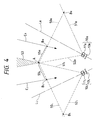
- Fig. 4 illustrates the principal part of the optical systems of the compound-eye image pickup device in Fig. 2, seen from a direction perpendicular to the plane defined by the optical axes L L , L R of the phototaking lens groups 11L, 11R.
- the color-separation prisms 12L, 12R (cf. Fig. 2) are omitted, and the CCD sensors 13L, 13R are illustrated in only one unit at each side.
- the phototaking lens group 11R and the CCD sensor 13R of the right-hand side image pickup system 10R have a focused object plane 50R, and the image taking is limited by the effective light-receiving area of the CCD sensor 13R into a range between lines 51R and 52R, so that an effective object field is defined on the focused object plane 50R, from a crossing point B R to a crossing point A with said lines 51R, 52R.
- an effective object field is similarly defined on the focused object plane 50L, from the crossing point A to a crossing point B L .
- the focusing motors 14L, 14R (cf. Fig. 2) and the zooming motors 16L, 16R (cf. Fig. 2) of the left and right-hand side image pickup systems 10L, 10R are so controlled that the distances between the focused object planes 50L, 50R and the CCD sensors 13L, 13R and the imaging magnifications are mutually same in the left- and right-hand sides.
- the motors, 14L, 14R, 16L, 16R, 18L, 18R are controlled by the operation control unit 20 (cf. Fig. 2) receiving the signals from the encoders 24L, 24R, 25L, 25R, 26L, 26R (cf. Fig. 3).
- the convergence angle motors 18L, 18R are controlled in relation to the positions of the focused object planes 50L, 50R and the positions of the effective-object fields, calculated from the output signals of the focus encoders 24L, 24R and the zoom encoders 25L, 25R.
- the corresponding point extraction unit 33 shown in Fig. 3 extracts paired corresponding points of the images.
- a representative method for such extraction is the template matching method.
- this method there is conceived a template surrounding a point for example in the left image, and corresponding points are determined by the comparison of similarity in the right image, with respect to the image in said template.
- the sign in front of i, j is inverted in the right and left images because the coordinate axis is defined symmetrically to the right and to the left as shown in Fig. 5B.
- the normalized mutual correlation represented by the equation (1) has a maximum value of unity.
- Another known method for this purpose is the DDSA method, which is also a kind of template matching method.
- the remnant difference is calculated by: In the course of calculation of summation, the calculation is interrupted when the remnant difference exceeds a predetermined threshold value, and the calculation proceeds to a next combination of (m R , n R ) and (m L , n L ).
- the threshold value is generally selected as the minimum value of the remnant difference in the past.
- the centers O L , O R of the object-side principal planes of the left and right phototaking lens groups 11L, 11R are positioned on the X-axis, symmetrically with respect to the Z-axis, and the length between said centers O L , O R is defined as the baseline length b.
- said centers O L and O R are represented by coordinates (-b/2, 0, 0) and (b/2, 0, 0). It should be noted that practically, the object is picked up by the optical system shown in Fig. 2, while it is assumed in Fig. 6 for convenience that the image pickup plain is at the position P L , P R in front of the lens optical system.
- a plane defined by the three points P, P L , P R in the three-dimensional space is called an epipolar plane, and the crossing line of the epipolar plane and the sensor plane is called an epipolar line.
- the coordinate (X, Y, Z) of the point P can be given by the following equations (3), (4) and (5):
- X ( b /2) • ⁇ X L + ( b /2) ⁇ / Z L + ⁇ X R -( b /2) ⁇ / Z R ⁇ X L + ( b /2) ⁇ / Z L - ⁇ X R -( b /2) ⁇ / Z
- Z R ⁇ X R - ( b /2) + f • sin( ⁇ ) ⁇ tan( ⁇ ) + f • cos( ⁇ )
- Z L - ⁇ X L + ( b /2) - f • sin( ⁇ ) ⁇ tan( ⁇ ) + f • cos( ⁇ )
- ⁇ is an angle (convergence angle) of the optical axes L L , L R of the left and right phototaking lens groups 11L, 11R to lines respectively passing the centers O L , O R of the object-side principal planes and parallel to the Z-axis
- f is the focal length of the phototaking lens groups 11L, 11R .
- the coordinate (X, Y, Z) of the point P can be determined from the foregoing equations.
- the coordinate conversion is conducted, based on the above-mentioned coordinate, to obtain an image seen from a point, for example from the middle point of the two image pickup systems.
- three axes are represented by X, Y, Z; rotational motions about the three axes by A, B, C; translational motions by U, V, W; focal length by f; coordinate axes in an image pickup plane by x, g; and a point on the image pickup plane corresponding to the object point P(X, Y, Z) by p(x, y).
- the object is picked up by the optical system shown in Fig. 2, while it is assumed in Fig. 6 for convenience that the image pickup plain is at the position P L , P R in front of the lens optical system.
- a point (x o ', y o ') corresponding to (x o , y o ) is represented by:
- the width (c) of the above-mentioned hatched area is given by:
- , wherein ⁇ 0 tan ⁇ 1 ( x 0/ f )
- G x + f • sinB / cos( B - ⁇ 0)
- the hatched areas do not contain the taken images, but the points corresponding to the image from (O, W) to (G, W) in the right image should be present, if the corresponding image exists, in a portion of a same width in the left image. Consequently, a range (d) in the left image lacks the corresponding points.
- a point (h, w) in the left image if G ⁇ h, should have a corresponding point, in the right image, within a range from (G, W) to (h, w).
- a portion corresponding to the errors is added to the above-mentioned basic search region, by substituting these parameters into the equation (10) to derive (X', Y', Z') anew and calculating (u, v) corresponding thereto.
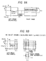
- a portion in consideration of the worst errors is usually added. For example a portion (i) shown in Fig. 9A is added in the vertical direction, and, in the horizontal direction, a portion (f) of (i) x (j) as shown in Fig. 9B is added.
- the extraction of the corresponding point is conducted after correction for the convergence angle of the images.
- the convergence angle of the images In the following there will be explained an embodiment without such correction of the convergence angle.
- the search range in the vertical direction is selected as the entire vertical range of the image or about a half thereof.
- the search range in the horizontal direction is selected, according to the consideration explained in the foregoing, as a hatched area (g) in Fig. 10.
- the search in searching the corresponding points in the images obtained from plural image pickup systems, the search is not conducted over the entire image but is limited in a portion thereof according to the phototaking parameters of the image pickup system, whereby the time required for extracting the corresponding point can be significantly reduced. Also such limitation of the search range eliminates extraction of erroneous corresponding point outside said search range, thereby improving the reliability.
- the search range is determined by adding a marginal range corresponding to such individual fluctuation to the basic search range determined from the phototaking parameters, whereby the search time can be reduced even in the presence of the errors, while maintaining the reliability of the search.
- a third embodiment of the present invention providing a method for extracting corresponding points in plural images, for clarifying the correspondence between time-sequentially obtained plural images or plural images obtained from plural image pickup systems, and an image processing unit therefor.
- the template matching method is known as a representative method for extraction of the corresponding points, for clarifying the correspondence among plural images.
- this method there is conceived a template surrounding a point, in a reference image, for which the corresponding point is to be searched, and the corresponding point is determined by calculating the similarity between said template and a range in the searched image.
- Fig. 11 for explaining the principle of the template matching method.
- a template 703 of a certain size around said point Q is prepared.
- This template 703 is moved in the searched image 702 with the calculation of similarity at each position, and the corresponding point to the point Q in the reference image 701 is determined at a position in the searched image 702 where the similarity is highest.
- F(i, j) indicates the searched image while A(i, j) indicates the template, and these equations provide the similarity when the template is at a position (x, y).
- the corresponding point is given where E(x, y) becomes minimum, and the theoretical minimum of E(x, y) is zero.
- the corresponding point is given where ⁇ (x, y) becomes maximum, of which theoretical maximum is 1.
- the template 802 or 803 can only be prepared for the points present in a central area 804 of the reference image, and the extraction of the corresponding point cannot be achieved for the points present in the peripheral area of the reference image 801. Similarly the similarity cannot be calculated in the entire searched image but only in the central area thereof.
- the object of the present embodiment is to provide a method for extracting corresponding points in plural images, and an image processing device therefor, enabling extraction of the corresponding point for any point in the entire reference image and also enabling calculation of similarity in the entire searched image, thereby improving the precision of extraction of the corresponding point.
- the above-mentioned object can be attained, according to the present embodiment, by a method of extracting corresponding points among plural images, based on the template matching method, for clarifying the correspondence among said plural images, wherein, in extracting the corresponding points in first and second images, the area of the template is varied depending on the position of said template on said first image.
- the area of the template is varied in case it is limited by the first image area in the peripheral portion thereof.
- the area of calculation is varied according to the overlapping said varied template and the second image.
- the calculation area is further varied in case it is limited by the second image area in the peripheral portion thereof.
- the image processing device of the present embodiment for clarifying the correspondence between plural images by the template matching method, comprises image input means for entering first and second images, and template varying means for varying the area of the template according to the position thereof on said first image.
- Said template varying means is provided with first area limiting means for limiting the area of said template to the area of said first image, in the peripheral portion thereof. It is further provided with calculation area varying means for varying the calculation area, based on the overlapping of said template varied in area and said second image. Said calculation area varying means is provided with second area limiting means for limiting said calculation area to the area of said second image in the peripheral portion thereof. It is further provided with moving object extraction means for extracting a moving object based on the extracted corresponding points. There is further provided epipolar conversion means for effecting epipolar conversion on the images prior to the extraction of the corresponding points, in case said first and second images are taken simultaneously with different image pickup devices. There is further provided distance calculation means for calculating the distance from the extracted corresponding points to the object.
- the template matching method of the above-explained configuration enables to prepare the template, for searching the corresponding point, in the entire area of the reference image, and to calculate the similarity in the entire area of the searched image.
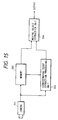
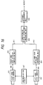
- Fig. 15 illustrates an example of the system relating to the extraction of corresponding points in the image processing device of the third embodiment.
- a camera 201 constituting an image pickup device; a memory 202 for storing the image obtained by the camera 201; a corresponding point extraction unit 203 for extracting corresponding points in the image stored in the memory 202 and an image currently obtained by the camera 201; and a moving object extraction unit 204 for extracting a moving object, based on moving vectors of the pixels, obtained by the corresponding point extraction unit 203.
- This system is used for precisely extracting a moving object from the image taken by the camera 201 and displaying the moving object only or cutting out the area of the moving object for the purpose of moving image compression.
- the above-explained system functions in the following manner.
- the image entered from the camera 201 is supplied to the memory 202 and the corresponding point extraction unit 203.
- the memory 202 has a capacity of plural images, in order that the currently entered image is not overwritten on the previously entered image.
- the corresponding point extraction unit 203 effects extraction of the corresponding points in the entire area of the entered image and an immediately preceding image from the memory 202, as will be explained later.
- the corresponding point extraction unit 203 determines movement vectors based on the immediately preceding input image.
- the moving object extraction unit 204 classifies the movement vectors of the pixels of the reference image, obtained in the corresponding point extraction unit 203, according to the direction and magnitude of the vectors, thus dividing the areas and extracts an area of the moving vectors, different from those of the background, as a moving object.
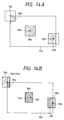
- Figs. 14A and 14B illustrate the preparation of the template in the reference image and the movement of the template in the searched image.
- hatched areas indicate templates 104 - 106 corresponding to points 101 - 103 for which the corresponding points are to be searched. If the image in Fig. 14A is taken as the reference image 110 from the memory 202, the template is prepared in the conventional manner in the central area of the reference image 110 (template 105). In the periportion of the reference image 110, an area of the same size as the template 105 in the central portion of the reference image 110 is considered about the point 101 or 103, and an overlapping portion of said area and the reference image 110 is defined as the template 104 or 106 (hatched areas in Fig. 14A).
- the template of a point in the central area of the reference image 110 has a size of 7 ⁇ 7 pixels
- the template 104 for the point 101 in Fig. 14A has a size of 4 ⁇ 4 pixels.
- the template for a point, for which the corresponding point is to be searched, in the peripheral portion of the reference image 110 is different in shape and size in comparison with the temperature for the point in the central area, and the position of the point for which the corresponding point is to be searched is displaced from the center of the template.
- Fig. 14B for explaining the method of calculating the similarity, with the above-explained template, in a searched image 120 entered from the camera 201.
- the template 106 in the reference image 110 shown in Fig. 14A is used.
- the point 103 for which the corresponding point is to be search is placed in succession on the points 111 - 113 in the search image 120 shown in Fig. 14B, whereupon overlapping between the template 106 and the searched image 120 takes place in grid-patterned areas in Fig. 14B.
- the similarity is calculated according to the foregoing equation (21) or (22), utilizing the pixel values in said grid-patterned areas.
- a moving object can be extracted with satisfactory precision in a system provided, as shown in Fig. 15, with the corresponding point extraction unit 203 enabling to prepare the template in the entire reference image and to move the template in the entire area of the searched image.
- the method of the present embodiment enables precise extraction of the moving area in the unit of each pixel, thereby achieving an improvement in the compression rate and an improvement in the resolving power when the image in expanded.
- Fig. 16 shows an example of the system for extracting the corresponding points in a fourth embodiment of the image processing device, adapted for obtaining the distance distribution of the object based on images obtained from plural cameras.
- a right-hand side camera 301 constituting an image pickup device
- a left-hand side camera 302 constituting an image pickup device
- a right-hand side epipolar conversion unit 303 for converting the image, obtained with a convergence angle by the right-hand side camera 301, into a state without convergence angle
- a left-hand side epipolar conversion unit 304 of a similar function a corresponding point extraction unit 305 for extracting the corresponding points of the images obtained by the right- and lefthand side epipolar conversion units 303, 304
- a distance measurement unit 307 for calculating, by trigonometric principle, the distance distribution of the object based on the corresponding points obtained from the corresponding point extraction unit 305
- a synchronization circuit 307 for synchronizing the timing of phototaking of the cameras 301, 302.
- the right- and left-hand side cameras 301, 302 simultaneously provide a right image 308 and a left image 309, which are subjected to epipolar conversion, into a state without convergence angle, respectively by the epipolar conversion units 303, 304.
- X, Y, Z three axes are represented by X, Y, Z; rotational motions about the three axes by A, B, C; transnational motions by U, V, W; focal length by f; coordinate axes in an image pickup plane by x, y; and a point on the image pickup plane corresponding to the object point P(X, Y, Z) by p(x, y).
- the epipolar conversion can be achieved by the above-written equations.
- Said convergence angle can be measured, for example by an encoder in the convergence angle control unit, though it is not illustrated in Fig. 17.
- the corresponding points are extracted from the right-hand side epipolar image 311 and the left-hand side epipolar image 312, obtained after the above-mentioned conversion, in the corresponding point extraction unit 305.
- the template With the left-hand side epipolar image 312 as the reference image, the template can be prepared in the entire area of the reference image as in the foregoing embodiment. However the movable range of the template within the searched right-hand side epipolar image 311 is different from that in the third embodiment.
- the obtained images are equivalent to those taken in a mutually parallel state. Consequently, in the vertical direction of the images, the corresponding points are present in a same height in the images. Consequently, for extracting the corresponding point of a point 504 in the reference image 501, the template 503 only needs to be moved in a single row as shown in Figs. 18A and 18B, and the calculation area in the searched image 502 varies as 505 - 507.
- the distance measurement unit 306 calculates the distance distribution of the object by the trigonometric method explained in the following.
- centers O L , O R of the object-side principal planes of the left and right phototaking lens groups 301, 302 are positioned on the X-axis, symmetrically with respect to the Z-axis, and the length between said centers O L , O R is defined as the baseline b, whereby the corinates of the centers O L , O R are represented respectively by (-b/2, 0, 0) and (b/2, 0, 0).
- the object is picked up by the optical system shown in Fig. 2, while it is assumed in Fig. 6 for convenience that the image pickup plain is at the position P L , P R in front of the lens optical system.
- the object is to determine the point P(X P , Y P , Z P )
- the system utilizing the corresponding point extraction unit 305 capable of extracting the points corresponding to all the pixels in the reference image, as shown in Fig. 16, can provide a smooth distance distribution in the pixel level, instead of the distribution in the unit of the image block.
- the images are subjected to epipolar conversion, but it is also possible to effect extraction of the corresponding points by moving the template in the entire area of the searched image without such epipolar conversion, as in the first embodiment.
- the corresponding points can be extracted for all the pixels in the reference image.
- the present invention is applicable either to a system composed of plural equipment, or to an apparatus consisting of a single equipment. It is naturally applicable also to a case where the present invention is achieved by the supply of a program to a system or an apparatus.
- the present invention in extracting the corresponding points among plural images, the present invention enables to determine the corresponding points for the entire area, where the corresponding points are present, in the reference image, whereby the corresponding points are obtained in a larger number and at a higher density than in the conventional method and the precision of extraction of the corresponding points can be improved.
Landscapes
- Engineering & Computer Science (AREA)
- Multimedia (AREA)
- Signal Processing (AREA)
- Physics & Mathematics (AREA)
- General Physics & Mathematics (AREA)
- Theoretical Computer Science (AREA)
- Computer Vision & Pattern Recognition (AREA)
- Testing, Inspecting, Measuring Of Stereoscopic Televisions And Televisions (AREA)
Applications Claiming Priority (4)
| Application Number | Priority Date | Filing Date | Title |
|---|---|---|---|
| JP181609/94 | 1994-08-02 | ||
| JP6181609A JPH0846855A (ja) | 1994-08-02 | 1994-08-02 | 複眼撮像装置 |
| JP30606694A JPH08161502A (ja) | 1994-12-09 | 1994-12-09 | 複数画像間の対応点抽出方法及び画像処理装置 |
| JP306066/94 | 1994-12-09 |
Publications (2)
| Publication Number | Publication Date |
|---|---|
| EP0696144A2 true EP0696144A2 (de) | 1996-02-07 |
| EP0696144A3 EP0696144A3 (de) | 1996-04-24 |
Family
ID=26500721
Family Applications (1)
| Application Number | Title | Priority Date | Filing Date |
|---|---|---|---|
| EP95305350A Withdrawn EP0696144A3 (de) | 1994-08-02 | 1995-07-31 | Bildaufnahmevorrichtung mit mehreren Linsen und einer Einheit zur Extraktion von übereinstimmenden Punkten |
Country Status (2)
| Country | Link |
|---|---|
| US (1) | US6236748B1 (de) |
| EP (1) | EP0696144A3 (de) |
Cited By (4)
| Publication number | Priority date | Publication date | Assignee | Title |
|---|---|---|---|---|
| GB2336963A (en) * | 1998-05-02 | 1999-11-03 | Sharp Kk | Controller for three dimensional display and method of reducing crosstalk |
| WO2002073980A1 (en) | 2001-03-14 | 2002-09-19 | Koninklijke Philips Electronics N.V. | Self adjusting stereo camera system |
| EP1087205A3 (de) * | 1999-09-22 | 2003-01-02 | Fuji Jukogyo Kabushiki Kaisha | Stereo-Abstandsmesser |
| KR101884565B1 (ko) * | 2017-04-20 | 2018-08-02 | 주식회사 이볼케이노 | 2차원 이미지를 이용한 객체의 3차원 모델링 장치 및 방법 |
Families Citing this family (27)
| Publication number | Priority date | Publication date | Assignee | Title |
|---|---|---|---|---|
| NO304715B1 (no) * | 1997-05-06 | 1999-02-01 | Dimensions As | FremgangsmÕte ved bildebehandling |
| JP3571893B2 (ja) * | 1997-12-03 | 2004-09-29 | キヤノン株式会社 | 画像記録装置及び画像記録方法、画像データベース生成装置及び画像データベース生成方法 |
| JP3349121B2 (ja) * | 1999-09-22 | 2002-11-20 | 富士重工業株式会社 | ステレオカメラの取付構造 |
| JP3760068B2 (ja) * | 1999-12-02 | 2006-03-29 | 本田技研工業株式会社 | 画像認識装置 |
| IL139995A (en) * | 2000-11-29 | 2007-07-24 | Rvc Llc | System and method for spherical stereoscopic photographing |
| US6947059B2 (en) * | 2001-08-10 | 2005-09-20 | Micoy Corporation | Stereoscopic panoramic image capture device |
| US20040201754A1 (en) * | 2001-10-12 | 2004-10-14 | Mcalister Micheal J. | Dual camera mounting arrangement for a wide screen imaging system |
| US7136171B2 (en) * | 2001-12-19 | 2006-11-14 | General Electric Company | Method for the extraction of image features caused by structure light using template information |
| US20040001145A1 (en) * | 2002-06-27 | 2004-01-01 | Abbate Jeffrey A. | Method and apparatus for multifield image generation and processing |
| US20060203085A1 (en) * | 2002-11-28 | 2006-09-14 | Seijiro Tomita | There dimensional image signal producing circuit and three-dimensional image display apparatus |
| JP3945430B2 (ja) * | 2003-03-19 | 2007-07-18 | コニカミノルタホールディングス株式会社 | 画像による対象物の計測方法および撮像装置 |
| KR20070007059A (ko) | 2003-12-26 | 2007-01-12 | 미코이 코포레이션 | 다중-차원 촬영 장치, 시스템, 및 방법 |
| JP4670303B2 (ja) * | 2004-10-06 | 2011-04-13 | ソニー株式会社 | 画像処理方法及び画像処理装置 |
| US7872665B2 (en) | 2005-05-13 | 2011-01-18 | Micoy Corporation | Image capture and processing |
| JP5409107B2 (ja) * | 2009-05-13 | 2014-02-05 | 任天堂株式会社 | 表示制御プログラム、情報処理装置、表示制御方法、および情報処理システム |
| US8462209B2 (en) * | 2009-06-26 | 2013-06-11 | Keyw Corporation | Dual-swath imaging system |
| JP5405264B2 (ja) | 2009-10-20 | 2014-02-05 | 任天堂株式会社 | 表示制御プログラム、ライブラリプログラム、情報処理システム、および、表示制御方法 |
| JP4754031B2 (ja) * | 2009-11-04 | 2011-08-24 | 任天堂株式会社 | 表示制御プログラム、情報処理システム、および立体表示の制御に利用されるプログラム |
| EP2355526A3 (de) | 2010-01-14 | 2012-10-31 | Nintendo Co., Ltd. | Computerlesbares Speichermedium mit einem Anzeigesteuerungsprogramm darauf, Anzeigesteuerungsvorrichtung, Anzeigesteuerungssystem und Anzeigesteuerungsverfahren |
| US9693039B2 (en) | 2010-05-27 | 2017-06-27 | Nintendo Co., Ltd. | Hand-held electronic device |
| WO2012049768A1 (ja) * | 2010-10-15 | 2012-04-19 | 株式会社モルフォ | 画像処理装置、画像処理方法及び画像処理プログラム |
| CN102081296B (zh) * | 2010-12-01 | 2012-11-07 | 南京航空航天大学 | 仿复眼视觉动目标快速定位及全景图同步获取装置及方法 |
| JP5956808B2 (ja) | 2011-05-09 | 2016-07-27 | キヤノン株式会社 | 画像処理装置およびその方法 |
| TWI578271B (zh) * | 2012-10-23 | 2017-04-11 | 義晶科技股份有限公司 | 動態影像處理方法以及動態影像處理系統 |
| CN103985134B (zh) * | 2014-06-04 | 2017-04-05 | 无锡维森智能传感技术有限公司 | 一种环视标定合成效果的检测方法 |
| US10437065B2 (en) * | 2017-10-03 | 2019-10-08 | Microsoft Technology Licensing, Llc | IPD correction and reprojection for accurate mixed reality object placement |
| CN120254572B (zh) * | 2025-05-30 | 2025-08-15 | 洛阳理工学院 | 一种基于电压信号处理的电子设备电性能测试装置及方法 |
Family Cites Families (12)
| Publication number | Priority date | Publication date | Assignee | Title |
|---|---|---|---|---|
| JP2603215B2 (ja) * | 1985-07-04 | 1997-04-23 | キヤノン株式会社 | 画像認識方法及び装置 |
| JP2649810B2 (ja) | 1987-10-28 | 1997-09-03 | 株式会社エイ・ティ・アール通信システム研究所 | 立体画像の冗長度圧縮装置 |
| US4819064A (en) * | 1987-11-25 | 1989-04-04 | The United States Of America As Represented By The Administrator Of The National Aeronautics And Space Administration | Television monitor field shifter and an opto-electronic method for obtaining a stereo image of optimal depth resolution and reduced depth distortion on a single screen |
| US4951140A (en) | 1988-02-22 | 1990-08-21 | Kabushiki Kaisha Toshiba | Image encoding apparatus |
| US5585945A (en) * | 1988-06-13 | 1996-12-17 | Canon Kabushiki Kaisha | Image synthesis with reduced memory requirements |
| JPH0220988A (ja) | 1988-07-08 | 1990-01-24 | Fujitsu Ltd | 動画像符号化装置における動ベクトル検出方式 |
| US4900128A (en) * | 1988-11-01 | 1990-02-13 | Grumman Aerospace Corporation | Three dimensional binocular correlator |
| US5577130A (en) * | 1991-08-05 | 1996-11-19 | Philips Electronics North America | Method and apparatus for determining the distance between an image and an object |
| EP0563737B1 (de) | 1992-03-23 | 1997-09-10 | Canon Kabushiki Kaisha | Bildaufnahmevorrichtung mit mehreren Linsen und Korrektur von Falschregistrierung |
| JPH05265081A (ja) * | 1992-03-23 | 1993-10-15 | Canon Inc | 複眼撮像装置 |
| JP2883265B2 (ja) | 1993-09-24 | 1999-04-19 | キヤノン株式会社 | 画像処理装置 |
| US5473383A (en) | 1994-06-15 | 1995-12-05 | Eastman Kodak Company | Mechanism for controllably deinterlacing sequential lines of video data field based upon pixel signals associated with three successive interlaced video fields |
-
1995
- 1995-07-31 EP EP95305350A patent/EP0696144A3/de not_active Withdrawn
- 1995-07-31 US US08/509,142 patent/US6236748B1/en not_active Expired - Lifetime
Non-Patent Citations (1)
| Title |
|---|
| None |
Cited By (7)
| Publication number | Priority date | Publication date | Assignee | Title |
|---|---|---|---|---|
| GB2336963A (en) * | 1998-05-02 | 1999-11-03 | Sharp Kk | Controller for three dimensional display and method of reducing crosstalk |
| US6573928B1 (en) | 1998-05-02 | 2003-06-03 | Sharp Kabushiki Kaisha | Display controller, three dimensional display, and method of reducing crosstalk |
| US7233347B2 (en) | 1998-05-02 | 2007-06-19 | Sharp Kabushiki Kaisha | Display controller, three dimensional display, and method of reducing crosstalk |
| EP1087205A3 (de) * | 1999-09-22 | 2003-01-02 | Fuji Jukogyo Kabushiki Kaisha | Stereo-Abstandsmesser |
| WO2002073980A1 (en) | 2001-03-14 | 2002-09-19 | Koninklijke Philips Electronics N.V. | Self adjusting stereo camera system |
| US8085293B2 (en) | 2001-03-14 | 2011-12-27 | Koninklijke Philips Electronics N.V. | Self adjusting stereo camera system |
| KR101884565B1 (ko) * | 2017-04-20 | 2018-08-02 | 주식회사 이볼케이노 | 2차원 이미지를 이용한 객체의 3차원 모델링 장치 및 방법 |
Also Published As
| Publication number | Publication date |
|---|---|
| US6236748B1 (en) | 2001-05-22 |
| EP0696144A3 (de) | 1996-04-24 |
Similar Documents
| Publication | Publication Date | Title |
|---|---|---|
| EP0696144A2 (de) | Bildaufnahmevorrichtung mit mehreren Linsen und einer Einheit zur Extraktion von übereinstimmenden Punkten | |
| EP0645926B1 (de) | Bildverarbeitungsvorrichtung und -verfahren. | |
| US5798791A (en) | Multieye imaging apparatus | |
| EP0971261B1 (de) | Vorrichtung zur Herstellung eines Stereoskopischen Bildes | |
| US6643396B1 (en) | Acquisition of 3-D scenes with a single hand held camera | |
| JP3107929B2 (ja) | 複眼撮像装置 | |
| JP2874710B2 (ja) | 三次元位置計測装置 | |
| US6839081B1 (en) | Virtual image sensing and generating method and apparatus | |
| US20070165129A1 (en) | Method of and apparatus for selecting a stereoscopic pair of images | |
| EP1087257B1 (de) | Stereoskopisches Kamerasystem in einem Fahrzeug | |
| JPH08336165A (ja) | 複眼撮像装置 | |
| JP2002077947A (ja) | 立体画像補正方法及びこれを用いた立体画像装置 | |
| KR100399047B1 (ko) | 교차축 입체 카메라의 주시각 제어 장치 및 그 방법 | |
| JPH0795621A (ja) | 画像記録再生装置 | |
| JPH10170227A (ja) | 表示装置 | |
| JP2003319418A (ja) | ステレオ画像表示方法およびステレオ画像表示装置 | |
| JP2974500B2 (ja) | 複眼撮像装置 | |
| JPH07177423A (ja) | 複眼撮像装置 | |
| JPH0799644A (ja) | 画像通信装置 | |
| JPH0846855A (ja) | 複眼撮像装置 | |
| JPH1023469A (ja) | 三次元情報処理装置及び三次元情報処理方法 | |
| JP3706642B2 (ja) | 撮像再生装置及び再生方法 | |
| JP2015022630A (ja) | 画像処理装置、画像処理方法およびプログラム | |
| Schenk et al. | Recovering epipolar geometry in 3-D vision systems | |
| JPH079673B2 (ja) | 両眼視系の対応点決定装置 |
Legal Events
| Date | Code | Title | Description |
|---|---|---|---|
| PUAI | Public reference made under article 153(3) epc to a published international application that has entered the european phase |
Free format text: ORIGINAL CODE: 0009012 |
|
| AK | Designated contracting states |
Kind code of ref document: A2 Designated state(s): DE FR GB |
|
| PUAL | Search report despatched |
Free format text: ORIGINAL CODE: 0009013 |
|
| AK | Designated contracting states |
Kind code of ref document: A3 Designated state(s): DE FR GB |
|
| 17P | Request for examination filed |
Effective date: 19960904 |
|
| 17Q | First examination report despatched |
Effective date: 19980528 |
|
| APAB | Appeal dossier modified |
Free format text: ORIGINAL CODE: EPIDOS NOAPE |
|
| APAB | Appeal dossier modified |
Free format text: ORIGINAL CODE: EPIDOS NOAPE |
|
| APAD | Appeal reference recorded |
Free format text: ORIGINAL CODE: EPIDOS REFNE |
|
| APAF | Appeal reference modified |
Free format text: ORIGINAL CODE: EPIDOSCREFNE |
|
| APAF | Appeal reference modified |
Free format text: ORIGINAL CODE: EPIDOSCREFNE |
|
| APBT | Appeal procedure closed |
Free format text: ORIGINAL CODE: EPIDOSNNOA9E |
|
| STAA | Information on the status of an ep patent application or granted ep patent |
Free format text: STATUS: THE APPLICATION HAS BEEN WITHDRAWN |
|
| 18W | Application withdrawn |
Effective date: 20060223 |