EP0696512B1 - Machine à imprimer par stencil - Google Patents
Machine à imprimer par stencil Download PDFInfo
- Publication number
- EP0696512B1 EP0696512B1 EP95305513A EP95305513A EP0696512B1 EP 0696512 B1 EP0696512 B1 EP 0696512B1 EP 95305513 A EP95305513 A EP 95305513A EP 95305513 A EP95305513 A EP 95305513A EP 0696512 B1 EP0696512 B1 EP 0696512B1
- Authority
- EP
- European Patent Office
- Prior art keywords
- stencil paper
- printing drum
- peripheral surface
- clamp plate
- outer peripheral
- Prior art date
- Legal status (The legal status is an assumption and is not a legal conclusion. Google has not performed a legal analysis and makes no representation as to the accuracy of the status listed.)
- Expired - Lifetime
Links
Images





Classifications
-
- B—PERFORMING OPERATIONS; TRANSPORTING
- B41—PRINTING; LINING MACHINES; TYPEWRITERS; STAMPS
- B41L—APPARATUS OR DEVICES FOR MANIFOLDING, DUPLICATING OR PRINTING FOR OFFICE OR OTHER COMMERCIAL PURPOSES; ADDRESSING MACHINES OR LIKE SERIES-PRINTING MACHINES
- B41L13/00—Stencilling apparatus for office or other commercial use
- B41L13/04—Stencilling apparatus for office or other commercial use with curved or rotary stencil carriers
Definitions
- the present invention relates to a mimeographic printing machine.
- a mimeographic printing machine of prior art having a stencil paper preparing device
- the leading edge of a mimeograph stencil paper wrapped around the outer peripheral surface of a printing drum is clamped by an openable-closable clamp plate.
- the printing paper is carried into the apparatus in synchronization with the rotation of the printing drum, and printing is performed by transferring the ink to this paper through the perforating section of the stencil paper wrapped around the printing drum.
- stencil paper discharge operation is carried out for example as follows. First, the clamp plate is opened to release the stencil paper. In this state, the printing drum is rotated to insert a stencil paper discharge craw into a stencil paper discharge position between the printing drum and the leading edge of the stencil paper raised from the outer peripheral surface of the printing drum. Thus the leading edge of the stencil paper is led between rollers, by which the stencil paper is stripped from the printing drum with the rotation of the rollers, being carried to be ejected out to the used stencil paper holding section.
- the stencil paper wrapped around the printing drum is clamped at the leading edge having an edge nearly parallel with the direction of the axis of the printing drum by means of an openable-closable clamp plate which rotates on the center of a shaft parallel with the direction of the axis of the printing drum.
- a larger part of the stencil paper located on the delay side in the direction of printing drum rotation is held on the outer peripheral surface of the printing drum with the adhesion of the ink supplied through the opening provided in the printing drum.
- the area ranging from the leading edge of the stencil paper to the opening area of the printing drum becomes free.
- This area of the stencil paper that has become free is curled (upward curl) in the direction in which the stencil paper goes away from the outer peripheral surface of the printing drum or is curled (downward curl) inwardly to approach the outer peripheral surface of the printing drum.
- the curling direction of the free leading edge of the stencil paper depends upon several conditions explained below.
- the stencil paper is generally supplied in the form of roll, and the rolled condition of the stencil paper determines the curling direction.
- the stencil paper is a laminate of a thermoplastic synthetic resin film and a porous substrate. When this stencil paper is rolled, the curling direction is determined by whether a portion appearing on the outermost surface is the thermoplastic synthetic resin film or the porous substrate. Temperature and humidity changes can be the factors that determine the curling direction.
- This raising member is designed to operate in connection with the opening and closing of the clamp plate; when the clamp plate is opened, the raising member rises in the vicinity of the leading edge to raise the leading edge off the outer peripheral surface of the printing drum, thereby providing a clearance between the outer peripheral surface of the printing drum and the raised leading edge of the stencil paper to thus prevent the adhesion of the stencil paper to the printing drum.
- JP-A-4-69073 discloses a mimeographic printing machine according to the preamble of claim 1.
- the present invention is characterized in the features of the characterizing portion of claim 1 with optional features in the dependant claims.
- the leading edge of the stencil paper that has been clamped by the clamping means on the outer peripheral surface of the printing drum becomes free.
- the stencil paper retaining member keeps the leading edge of the stencil paper in an appropriately raised state, thereby allowing the movement of the leading edge of the stencil paper to the stencil paper conveying means without being affected by the rotational speed of the printing drum at the time of stencil paper discharge.
- the stencil paper raised by the raising member curls in a direction in which it approaches the outer peripheral surface of the printing drum, the stencil paper can be prevented from slipping down to the delay side of printing drum rotation if caused by the rise of the raising member because the vicinity of the leading edge is held on the outer peripheral surface of the printing drum by means of the stencil paper retaining member. Therefore, there is properly formed a clearance between the outer peripheral surface of the printing drum and the stencil paper into which the stencil paper discharge craw can be inserted, thus properly leading the leading edge of the stencil paper to the conveying means.
- Fig. 1 shows one embodiment of the mimeographic printing machine of the present invention.
- the mimeographic printing machine 1 has an original image reading section 20, a thermal stencil paper preparing section 30, a mimeograph mechanism section 40, a stencil paper discharge section 50, a paper feeding section 60, and a paper delivery section 70.
- the original image reading section 20 has an original setting table 21, a pair of original feed rollers 22, an image sensor 23 of for example a contact type which optically reads an original image and converts it to an electric signal, and an original discharge tray 24 for stacking the original copy after reading the image.
- the stencil paper making section 30 has a thermal head 31 provided with a plurality of heating elements arranged perpendicularly to the paper surface in the drawing, and a platen roller 32 provided oppositely to the thermal head 31, so that the mimeograph stencil paper S can be thermally perforated and conveyed to the printing drum 2 side described later.
- a pair of upper and lower original feed rollers 33 Adjacently to the thermal head 31 and the platen roller 32 there are mounted a pair of upper and lower original feed rollers 33, a stencil paper cutter 36 consisting of a pair of upper and lower blades, that is, a fixed blade 34 and a movable blade 35, for cutting a series of perforated stencils S to each stencil paper, and a stencil paper guide plate 39 consisting of a lower stencil paper guide plate 37 and an upper stencil paper guide plate 38 for guiding the prepared stencil paper S to the clamping section of the printing drum 2 described later.
- the mimeograph mechanism section 40 has the cylindrical printing drum 2 rotatable on the center axis thereof and having an ink pervious area.
- the printing drum 2 is driven by a main motor 3 to rotate in a clockwise direction in Fig. 1.
- a stencil paper clamp section as a clamping means which comprises a stage section 4 and a clamp plate 5 for clamping one end of the stencil paper in cooperation with the stage section 4.
- the clamp plate 5 is designed to turn through about 180 degrees on the stage section 4, to thereby selectively clamp or unclamp the leading edge of the stencil paper S.
- an ink supply mechanism section 9 including a squeegee roller 7 and a doctor rod 8, thereby enabling to supply the ink to the inner peripheral surface of the printing drum 2.
- an impression roller 10 is vertically movably mounted. The impression roller 10 presses, against the outer peripheral surface of the printing drum 2, the paper P that has been fed in between the printing drum 2 and the impression roller 10 in synchronization with the rotation of the printing drum 2, thus transferring to the paper P the ink supplied through the ink-pervious area of the printing drum 2 and the opening area of the stencil paper S.
- the stencil paper discharge section 50 has a stencil paper discharge craw 51.
- the stencil paper discharge craw 51 is pivotally supported on a shaft 52, and with its base end portion a solenoid 53 for driving the stencil paper discharge craw is interconnected.
- the solenoid 53 for driving the stencil paper discharge craw is driven, the stencil paper discharge craw 51 is rotated within the range of specific angle on the center of the shaft 52. That is, the stencil paper discharge craw 51 is driven so that the leading edge of the stencil paper discharge craw 51 will move between the stencil paper S stripping position near the surface of the printing drum 2 and the waiting position apart by a specific distance from the printing drum 2.
- the stencil paper S that has been stripped from the printing drum 2 at the stripping position is guided in a direction (to the right in Fig. 1) in which the stencil paper S will come off the printing drum 2.
- a pair of stencil paper discharge rollers 56 including an upper roller 54 and a lower roller 55 for conveying the stencil paper S.
- a discharged stencil paper storing box 57 Adjacently to the stencil paper discharge rollers 56, in the direction of conveyance, a discharged stencil paper storing box 57 is provided for discharging and storing used stencils S conveyed on the stencil paper discharge rollers 56.
- the paper feed section 60 has a paper feed table 61 for load the printing paper P which is driven to move up and down by a means of a vertically moving mechanism not shown, a pickup roller 62 for taking out the paper P one by one from the paper feed table 61, a paper feed clutch 63 for intermittently transmitting the rotation of the main motor 3 to the pickup roller 62, and a pair of paper conveying rollers 64 for feeding the paper P at a specific timing between the printing drum 2 and the impression roller 10.
- the paper delivery section 70 has a separating craw 71 for separating the printed paper P from the printing drum 2, and a belt conveyor-type delivery apparatus 73 for conveying the printed paper P stripped from the printing drum 2 by the separating craw 71, to the paper receiving tray 72.
- the printing drum 2 has a generally cylindrical shape with a pair of flanges 12 and 13 having rigidity inserted in both open ends of a cylindrical peripheral wall 11; the peripheral wall 11 and both flanges 12 and 13 are fastened by fastening means such as screws.
- fastening means such as screws.
- the peripheral wall of the printing drum 2 has a rectangular opening section O which is an ink-pervious area having a number of openings, and an unopening section N which is an ink-impervious area.
- the perforated image section corresponds to the opening section O. Therefore, the ink supplied to the inner surface of the printing drum 2 during printing from the ink supply mechanism section provided inside the printing drum 2 passes out through the opening section O of the printing drum 2 and the perforated image section of the stencil paper S, being transferred to the paper P which is pressed against the outer peripheral surface of the printing drum 2.
- a stage section 4 having two flat surfaces A and B arranged in the direction of rotation of the printing drum 2 is fastened by screws.
- the flat surfaces A serve as a stencil paper support surfaces which, together with the clamp plate 5, holds the leading edge of the stencil paper.
- two types of bearings 14 and 15 are juxtaposed along a direction parallel with the rotating shaft of the printing drum within the range between the flat surfaces A and B arranged in the direction of rotation of the printing drum 2.
- a pair of pivot shafts 16 which are rotatably supported on the bearings 14 and 15, so that the clamp plate 5 is rotatable on the center of these pivot shafts 16.
- a gear 17 is mounted on the outer end part of one pivot shaft 16 of the clamp plate 5.
- a clamp solenoid 18 shown in Fig. 1 is mounted on the body frame side which is a fastening member not shown.
- the clamp solenoid 18 can move up and down a clamp driving unit 19 having a driving gear 19a and a motor not shown which is a driving power source of the driving gear 19a, and can move the driving gear 19a into selective mesh with the gear 19 of the pivot shaft 16.
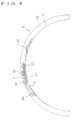
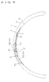
- the clamp plate 5 rotates through about 180 degrees on the stage section 4 of the printing drum 2. That is, the clamp plate 5 is driven to rotate on the center of the pivot shaft 16 between the clamp position (the position shown in Figs.
- a plurality of rectangular magnetic plates 40 are fixed in a row on the flat surface A of the stage section 4.
- the clamp plate 5 holding the leading edge of the stencil paper S, when attracted to the upper surface of the magnetic plate 40, is fixed in the clamp position and the leading edge of the stencil paper is clamp on the outer peripheral surface of the printing drum 2.
- a belt-like magnetic plate 41 is provided along the direction of a generating line of the printing drum 2, on the flat surface B of the stage section 4. The clamp plate 5, when attracted to the upper surface of this magnetic plate 41, is fastened in the unclamp position where the stencil paper S is not clamped.
- the clamp plate 5 can rotate between the clamp position shown in Figs. 2 and 3 in which the clamp plate 5 is magnetically attracted by the magnetic plate 40 to hold the leading edge of the stencil paper S and the unclamp position shown in Figs. 4 and 5 in which the clamp plate is turned through 180 degrees from the clamp position and magnetically attracted by the other magnetic plate 41.
- stencil paper holding means 80 and 90 are provided in both positions off the clamp area of the stencil paper S, in the vicinity of both ends of the clamp plate 5, on the stage section 4.
- the stencil paper holding means 80 and 90 are members for retaining both sides near the leading edge of the stencil paper S on the outer peripheral surface of the printing drum 2, that is, on the upper surface of the stage section 4 in the present embodiment, when the clamp plate 5 is released.
- a driven member 81 which is an approximately L-shaped plate member is rotatably attached by a screw 82 in relation to the stage section 4.
- a torsion coil spring 83 as an energizing member.
- One arm 83a of the torsion coil spring 83 is held on the flange 13, while the other arm 83b is engaged in a slot section 84a formed in the vertical piece 83 of the driven member 81. Therefore the driven member 81, though pressed towards the center of the printing drum 2 on the center of the screw 82, is engaged with a part of the bearing 15 as shown in Fig. 6, being checked from further rotation.
- the other arm 83b of the torsion coil spring 83 has a ring-like end, which serves as a holding member 85 for holding the stencil paper S.
- the clamp plate 5 is open and the holding member 85 formed in a shape of ring is holding, on the upper surface of the stage section 4, the side part of the stencil paper S at a specific distance on the delay side of rotation of the printing drum 2 from the leading edge of the stencil paper S.
- the holding member 85 moves between the holding position where the side part of the stencil paper S is held by the holding member 85 and the non-holding position apart from the holding position, particularly when the holding member 85 moves from the non-holding position to the holding position, the side part of the stencil paper S must not be caught and turned up by the forward end of the holding member 85.
- the adoption of the ring-shaped holding member 85 can prevent this trouble. That is, the holding member 85 may be of any other shape than the ring shape so long as it can obviate the above-described disadvantage. Also, any other member such as a spherical resin member may be installed on the forward end of the arms 83b and 93b.
- This stencil paper holding member 90 also has a driven member 91 rotatably supported by fastening by a screw 92 to the stage section 4.
- a screw 92 To this screw 92 is installed the torsion coil spring 93 as an energizing member.
- One arm 93a of the torsion coil spring 93 is engaged with the bearing 16, while the other arm 93b is engaged in the slot 94a formed in the vertical piece 94 of the driven member 91. Therefore, an engaging section 94c formed on the vertical piece 94 of the driven member 91 is engaged with the side part of the stage section 4 located on the flange 12 side as shown in Fig. 7, thereby being checked from further rotation.
- the forward end of the other arm 93b of the torsion coil spring 93 is formed in a shape of ring, which portion serves as a holding member 95 for holding the stencil paper S.
- the clamp plate 5 is open and the holding member 95 formed in the shape of ring holds on the upper surface of the stage section 4 the side part of the stencil paper S at a specific distance apart towards the delay side of rotation of the printing drum 2 from the leading edge of the stencil paper S.
- the holding members 85 and 95 of the stencil paper holding means function to hold both sides near the leading edge of the stencil paper S to the stage section 4 as shown in Figs. 4, 6 and 7.
- a raising member 100 which functions with the opening and closing operation of the clamp plate 5.
- This raising member 100 is a member which forces to raise the vicinity of the leading edge of the stencil paper S from the stage section 4 when the clamp plate 5 is opened, thereby facilitating the following stripping operation to remove the stencil paper S from the printing drum 2.
- the raising member 100 is an elastic sheet-like member, which can be produced of for example an approximately 0.5 to 0.005 mm thick polyester sheet, carbon fiber sheet, etc.
- the base section 101 of the raising member 100 is secured on the flat surface A of the stage section 4.
- the base section 101 of the raising member 100 is a belt-like member disposed longitudinally along the axis of the printing drum 2; the length thereof in the lengthwise direction is equal to the width of the stencil paper S.
- a plurality of slender belt-like raising sections 102 are extended as one unit.
- Each of the belt-like raising sections 102 is disposed in a position corresponding to a gap between a plurality of magnetic plates.
- On the stage section 4 between the flat surfaces A and B is provided a shaft 103 parallel with the axis of the printing drum 2. Furthermore, each of the raising sections 102 passes under the shaft 103, being led to the other magnetic plate 41 side; and the forward end of the raising section 102 is secured to the clamp plate 5.
- the clamp plate 5 when turned through about 180 degrees from the state shown in Figs. 2 and 3, is attracted by the other magnetic plate 41 as shown in Figs. 4 and 5, thereby unclamping the stencil paper S.
- the clamp plate 5 rotates towards releasing the stencil paper as described above, the raising section 102 surrounding the shaft 103 is pushed out to the stencil paper S side.
- the raising section 102 being secured together with the base section 101 on the stage section 4, rises, at the shaft 103, into a curved form on the flat surface A side of the stage section 4.
- the stencil paper S released from the clamp plate 5 is forced to separate from the upper surface of the magnetic plate 40 by the operation of the raising section 102 which moves upwards, even if the leading edge of the stencil paper S is held electrostatically or otherwise in close contact with the upper surface of the magnetic plate 40.
- the mimeograph stencil paper S is wrapped around the printing drum 2 with the leading edge thereof fixed by means of the clamp plate 5 when printing is performed.
- the holding members 85 and 95 of the stencil paper holding means 80 and 90 are released from the stencil paper S, and therefore the printing operation will be performed without any trouble.
- the printing drum 2 is positioned in a position shown in Fig. 1.
- the clamp solenoid 18 is energized to move the driving gear 19a of the clamp driving unit 19 into mesh with the gear 17 mounted on the pivot shaft 16 of the clamp plate 5.
- the driving gear 19a of the clamp driving unit 19 is driven to thereby rotate the gear 17, the clamp plate 5 clamping the stencil paper S turns in a direction in which the clamp plate 5 moves away from the stencil paper S.
- the clamp plate 5 is attracted by the magnetic plate 41, thus releasing the stencil paper S.
- the printing drum 2 rotates clockwise in Fig. 1.
- the stencil paper discharge craw driving solenoid 53 operates in synchronization with the rotation of the printing drum 2, moving the stencil paper discharge craw 51 towards approaching the printing drum 2, being set in a position in which the stencil paper S is removed. Then, the leading edge of the stencil paper S thus released is guided by the stencil paper discharge craw 51 to the stencil paper discharge rollers 56.
- the stencil paper S is peeled from the printing drum 2 by the rotation of the printing drum 2 and the stencil paper discharge rollers 56, and is stored in the discharged stencil paper storing box 57.
- the holding members 85 and 95 of the stencil paper holding means 80 and 90 hold both sides near the leading edge of the stencil paper S to the stage section 4 as shown in Figs. 4, 6 and 7.
- the stencil paper holding means 80 and 90 hold the stencil paper S in an appropriately raised state even in the case the stencil paper S is curled (upward curl) off the outer peripheral surface of the printing drum 2.
- the stencil paper S can be properly guided to the stencil paper discharge rollers 56 without being affected by the speed of rotation of the printing drum 2 at the time of stencil paper discharge.
- the raising member 100 and the stencil paper holding means 80 and 90 are provided in the present embodiment, the vicinity of the leading edge of the stencil paper S is pressed to the outer peripheral surface of the printing drum 2 by the stencil paper holding means 80 and 90 when raised by the raising section 102, thereby preventing the dislocation of the stencil paper S from the printing drum 2 and accordingly properly forming a gap between the printing drum 2 and the stencil paper S into which the stencil paper discharge craw 51 can be inserted to guide the leading edge of the stencil paper S properly to the stencil paper discharge rollers 56.
- the vicinity of the leading edge of the stencil paper S is held by the holding members 85 and 95 of the stencil paper holding means 80 and 90 in such a position between the base end of the raising section 102 and the opening section O that the raising operation of the raising section 102 will not be interfered with.
- the mimeographic printing machine of the present invention has a stencil paper holding means for holding the vicinity of the leading edge of the stencil paper on the printing drum side when the clamping means clamping the leading edge of the stencil paper wrapped around the printing drum is released.
- a stencil paper jam resulting from the curling of the leading edge of the stencil paper when the stencil paper is released from the clamping means can be prevented, allowing properly guiding the leading edge of the stencil paper to the stencil paper discharge section. Smooth discharge of the paper after release from the clamping means is obtained.
Landscapes
- Separation, Sorting, Adjustment, Or Bending Of Sheets To Be Conveyed (AREA)
- Manufacture Or Reproduction Of Printing Formes (AREA)
- Screen Printers (AREA)
- Supply, Installation And Extraction Of Printed Sheets Or Plates (AREA)
Claims (7)
- Machine d'impression par stencil, comportant:un tambour d'impression cylindrique (2) qui présente une zone perméable à l'encre pour laisser passer l'encre d'une surface périphérique intérieure vers une surface périphérique externe, et est entraíné en rotation sur son axe central avec un papier de stencil (S) ayant une zone perforée enroulé autour de ladite surface périphérique externe;des moyens d'alimentation en encre (9) prévus dans ledit tambour d'impression, afin de délivrer l'encre à ladite surface périphérique intérieure; etdes moyens de retenue (5) prévus sur ladite surface périphérique externe dudit tambour d'impression (2), afin de maintenir sur ledit tambour d'impression (2) un bord avant dudit papier de stencil (S) enroulé autour de ladite surface périphérique externe; et caractérisée par :des moyens de maintien de papier de stencil (80, 90) prévus sur ladite surface périphérique externe dudit tambour d'impression (2), afin de maintenir sur ledit tambour d'impression (2) le voisinage du bord avant dudit papier de stencil (S) quand lesdits moyens de retenue (5) ont relâché ledit papier de stencil (S.).
- Machine d'impression par stencil selon la revendication 1, dans laquelle lesdits moyens de maintien de papier de stencil (80, 90) sont agencés afin de relâcher ledit papier de stencil (S) lorsque lesdits moyens de retenue (5 ) ont serré ledit papier de stencil (S).
- Machine d'impression par stencil selon la revendication 2, dans laquelle lesdits moyens de retenue (5) ont un arbre (16) prévu sur ladite surface périphérique externe dudit tambour d'impression (2) parallèlement à l'axe central dudit tambour d'impression (2), et une plaque de serrage (5) tournant sur le centre dudit arbre (16).
- Machine d'impression par stencil selon la revendication 3, dans laquelle lesdits moyens de maintien de papier de stencil (80, 90) ont un élément entraíne (81, 91) qui est prévu sur ladite surface périphérique externe dudit tambour d'impression (2) afin d'être mobile entre l'intérieur et l'extérieur de la plage de rotation de ladite plaque de serrage (5), et se déplace hors de la plage de rotation de ladite plaque de serrage (5), en contact avec la partie d'extrémité de ladite plaque de serrage (5) qui tourne; un élément d'activation (83, 93) destiné à activer pour une mise en place de l'élément entraíné (81, 91) dans la plage de rotation de ladite plaque de serrage (5); et un élément de maintien (85, 95) prévu sur ledit élément entrainé (81, 91), afin de maintenir sur ledit côté de tambour d'impression le voisinage du bord avant dudit papier de stencil (S) quand ledit élément entraíné (81, 91) a été placé dans la plage de rotation de ladite plaque de serrage (5).
- Machine d'impression par stencil selon la revendication 4, comportant en outre : un élément de soulèvement (100) prévu sur ladite surface périphérique externe dudit tambour d'impression (2), qui se dresse à l'extérieur de ladite surface périphérique externe dudit tambour d'impression (2) afin de soulever ledit papier de stencil (S) à l'écart de ladite surface périphérique externe dudit tambour d'impression (2) lorsque ledit papier de stencil (S) est relâché par lesdits moyens de retenue (5).
- Machine d'impression par stencil selon la revendication 5, dans laquelle lesdits moyens de retenue (5) ayant une surface de support de papier de stencil (A) sur ladite surface périphérique externe dudit tambour d' impression (2) afin de maintenir le bord avant dudit papier de stencil (S) entre ladite surface de support de papier de stencil (A) et ladite plaque de serrage (5).
- Machine d'impression par stencil selon la revendication 6, dans laquelle ledit élément de soulèvement (100) est une pièce mince élastique fixée à une extrémité par ladite plaque de serrage (5) et à l'autre extrémité sur ladite surface périphérique externe dudit tambour d'impression (2), et une partie entre ladite première extrémité et ladite autre extrémité est disposée au moins en partie au-dessus d'au moins une partie de ladite surface de support de papier de stencil (A), et ledit élément de soulèvement (100) se dresse à l'écart de ladite surface de support de papier de stencil (A) lorsque ladite plaque de serrage (5) se déplace à l'écart de ladite surface de support de papier de stencil (A).
Applications Claiming Priority (2)
| Application Number | Priority Date | Filing Date | Title |
|---|---|---|---|
| JP185791/94 | 1994-08-08 | ||
| JP6185791A JPH0848069A (ja) | 1994-08-08 | 1994-08-08 | 孔版印刷装置 |
Publications (2)
| Publication Number | Publication Date |
|---|---|
| EP0696512A1 EP0696512A1 (fr) | 1996-02-14 |
| EP0696512B1 true EP0696512B1 (fr) | 1998-10-28 |
Family
ID=16176963
Family Applications (1)
| Application Number | Title | Priority Date | Filing Date |
|---|---|---|---|
| EP95305513A Expired - Lifetime EP0696512B1 (fr) | 1994-08-08 | 1995-08-08 | Machine à imprimer par stencil |
Country Status (4)
| Country | Link |
|---|---|
| US (1) | US5566612A (fr) |
| EP (1) | EP0696512B1 (fr) |
| JP (1) | JPH0848069A (fr) |
| DE (1) | DE69505609T2 (fr) |
Families Citing this family (1)
| Publication number | Priority date | Publication date | Assignee | Title |
|---|---|---|---|---|
| JP2005199471A (ja) | 2004-01-13 | 2005-07-28 | Riso Kagaku Corp | 孔版印刷装置 |
Family Cites Families (8)
| Publication number | Priority date | Publication date | Assignee | Title |
|---|---|---|---|---|
| US1497149A (en) * | 1922-11-25 | 1924-06-10 | Lehmann Karl August Albert | Duplex-card-stamping apparatus |
| US3948169A (en) * | 1974-11-14 | 1976-04-06 | Weber Marking Systems, Inc. | Coaxially mounted stencil drum and rubber mat roller segments |
| JPS5996983A (ja) * | 1982-11-26 | 1984-06-04 | Riso Kagaku Corp | 孔版式製版印刷装置 |
| JPS61104854A (ja) * | 1984-10-29 | 1986-05-23 | Riso Kagaku Corp | 印刷装置の原紙係止装置 |
| JP2828462B2 (ja) * | 1989-06-22 | 1998-11-25 | 理想科学工業株式会社 | 孔版印刷装置 |
| JPH0469073A (ja) * | 1990-07-03 | 1992-03-04 | Asmo Co Ltd | 回転位置検出器を備えた超音波モータ |
| JP3026677B2 (ja) * | 1992-05-20 | 2000-03-27 | 株式会社リコー | 孔版印刷機の排版装置 |
| JP3283090B2 (ja) * | 1993-03-18 | 2002-05-20 | 理想科学工業株式会社 | 孔版原紙の着版方法および孔版印刷用版胴 |
-
1994
- 1994-08-08 JP JP6185791A patent/JPH0848069A/ja active Pending
-
1995
- 1995-07-27 US US08/507,842 patent/US5566612A/en not_active Expired - Fee Related
- 1995-08-08 DE DE69505609T patent/DE69505609T2/de not_active Expired - Fee Related
- 1995-08-08 EP EP95305513A patent/EP0696512B1/fr not_active Expired - Lifetime
Also Published As
| Publication number | Publication date |
|---|---|
| EP0696512A1 (fr) | 1996-02-14 |
| US5566612A (en) | 1996-10-22 |
| JPH0848069A (ja) | 1996-02-20 |
| DE69505609T2 (de) | 1999-03-25 |
| DE69505609D1 (de) | 1998-12-03 |
Similar Documents
| Publication | Publication Date | Title |
|---|---|---|
| EP0110204B1 (fr) | Duplicateur à stencil permettant l'impression automatique ainsi que la perforation, le chargement et la sortie automatique du stencil | |
| JPH09201934A (ja) | シートロールの自動先端剥離装置および製版装置 | |
| US5535671A (en) | Stencil duplicating machine applying uniform tension to a stencil | |
| US4966073A (en) | Mimeographic printing apparatus with a stencil guide | |
| US5566612A (en) | Mimeographic printing machine | |
| EP0713768B1 (fr) | Dispositif de montage de l'extrémité avant d'un stencil dans une machine rotative d'impression par stencil | |
| US5782178A (en) | Stencil printer | |
| JP3350258B2 (ja) | 排版装置 | |
| EP1086824B1 (fr) | Machine d'impression au pochoir | |
| US6382093B1 (en) | Stencil printing machine having controlled transport of stencil to container | |
| EP0860293B1 (fr) | Dispositif de déchargement d'un stencil d'une presse rotative avec protection contre contamination d'encre | |
| JP3746562B2 (ja) | 孔版印刷装置の排紙・搬送装置 | |
| JP2813301B2 (ja) | 孔版印刷装置 | |
| JP3768631B2 (ja) | 製版印刷装置 | |
| JP4462707B2 (ja) | 製版装置および孔版印刷装置 | |
| US5513564A (en) | Stencil duplicating machine | |
| KR0168236B1 (ko) | 공판식 제판인쇄장치의 착판 및 배판장치 | |
| JPH06255227A (ja) | 孔版印刷装置の給排版装置 | |
| EP1072426B1 (fr) | Unité et méthode pour retirer un stencil | |
| KR0168237B1 (ko) | 공판식 인쇄기기의 인쇄용 원지필름 장착기구 | |
| JPH0811415A (ja) | 孔版印刷装置 | |
| JP2640232B2 (ja) | 孔版印刷用原紙の処理装置 | |
| JPH02273Y2 (fr) | ||
| JPH04129787A (ja) | 輪転式孔版印刷装置 | |
| JP2008307715A (ja) | 孔版印刷装置 |
Legal Events
| Date | Code | Title | Description |
|---|---|---|---|
| PUAI | Public reference made under article 153(3) epc to a published international application that has entered the european phase |
Free format text: ORIGINAL CODE: 0009012 |
|
| AK | Designated contracting states |
Kind code of ref document: A1 Designated state(s): DE FR GB |
|
| 17P | Request for examination filed |
Effective date: 19960704 |
|
| 17Q | First examination report despatched |
Effective date: 19970523 |
|
| GRAG | Despatch of communication of intention to grant |
Free format text: ORIGINAL CODE: EPIDOS AGRA |
|
| GRAG | Despatch of communication of intention to grant |
Free format text: ORIGINAL CODE: EPIDOS AGRA |
|
| GRAG | Despatch of communication of intention to grant |
Free format text: ORIGINAL CODE: EPIDOS AGRA |
|
| GRAH | Despatch of communication of intention to grant a patent |
Free format text: ORIGINAL CODE: EPIDOS IGRA |
|
| GRAH | Despatch of communication of intention to grant a patent |
Free format text: ORIGINAL CODE: EPIDOS IGRA |
|
| GRAA | (expected) grant |
Free format text: ORIGINAL CODE: 0009210 |
|
| AK | Designated contracting states |
Kind code of ref document: B1 Designated state(s): DE FR GB |
|
| REF | Corresponds to: |
Ref document number: 69505609 Country of ref document: DE Date of ref document: 19981203 |
|
| ET | Fr: translation filed | ||
| PLBE | No opposition filed within time limit |
Free format text: ORIGINAL CODE: 0009261 |
|
| STAA | Information on the status of an ep patent application or granted ep patent |
Free format text: STATUS: NO OPPOSITION FILED WITHIN TIME LIMIT |
|
| 26N | No opposition filed | ||
| REG | Reference to a national code |
Ref country code: GB Ref legal event code: IF02 |
|
| PGFP | Annual fee paid to national office [announced via postgrant information from national office to epo] |
Ref country code: GB Payment date: 20030724 Year of fee payment: 9 Ref country code: FR Payment date: 20030724 Year of fee payment: 9 |
|
| PG25 | Lapsed in a contracting state [announced via postgrant information from national office to epo] |
Ref country code: GB Free format text: LAPSE BECAUSE OF NON-PAYMENT OF DUE FEES Effective date: 20040808 |
|
| PGFP | Annual fee paid to national office [announced via postgrant information from national office to epo] |
Ref country code: DE Payment date: 20041028 Year of fee payment: 10 |
|
| GBPC | Gb: european patent ceased through non-payment of renewal fee |
Effective date: 20040808 |
|
| PG25 | Lapsed in a contracting state [announced via postgrant information from national office to epo] |
Ref country code: FR Free format text: LAPSE BECAUSE OF NON-PAYMENT OF DUE FEES Effective date: 20050429 |
|
| REG | Reference to a national code |
Ref country code: FR Ref legal event code: ST |
|
| PG25 | Lapsed in a contracting state [announced via postgrant information from national office to epo] |
Ref country code: DE Free format text: LAPSE BECAUSE OF NON-PAYMENT OF DUE FEES Effective date: 20060301 |