EP0697062B1 - Procede et dispositif permettant l'apport regule d'un agent reducteur dans des gaz d'echappement contenant de l'oxyde nitrique - Google Patents
Procede et dispositif permettant l'apport regule d'un agent reducteur dans des gaz d'echappement contenant de l'oxyde nitrique Download PDFInfo
- Publication number
- EP0697062B1 EP0697062B1 EP94913016A EP94913016A EP0697062B1 EP 0697062 B1 EP0697062 B1 EP 0697062B1 EP 94913016 A EP94913016 A EP 94913016A EP 94913016 A EP94913016 A EP 94913016A EP 0697062 B1 EP0697062 B1 EP 0697062B1
- Authority
- EP
- European Patent Office
- Prior art keywords
- catalytic converter
- exhaust gas
- reducing agent
- reducing
- converter unit
- Prior art date
- Legal status (The legal status is an assumption and is not a legal conclusion. Google has not performed a legal analysis and makes no representation as to the accuracy of the status listed.)
- Expired - Lifetime
Links
Images

Classifications
-
- F—MECHANICAL ENGINEERING; LIGHTING; HEATING; WEAPONS; BLASTING
- F01—MACHINES OR ENGINES IN GENERAL; ENGINE PLANTS IN GENERAL; STEAM ENGINES
- F01N—GAS-FLOW SILENCERS OR EXHAUST APPARATUS FOR MACHINES OR ENGINES IN GENERAL; GAS-FLOW SILENCERS OR EXHAUST APPARATUS FOR INTERNAL-COMBUSTION ENGINES
- F01N11/00—Monitoring or diagnostic devices for exhaust-gas treatment apparatus
-
- B—PERFORMING OPERATIONS; TRANSPORTING
- B01—PHYSICAL OR CHEMICAL PROCESSES OR APPARATUS IN GENERAL
- B01D—SEPARATION
- B01D53/00—Separation of gases or vapours; Recovering vapours of volatile solvents from gases; Chemical or biological purification of waste gases, e.g. engine exhaust gases, smoke, fumes, flue gases, aerosols
- B01D53/30—Controlling by gas-analysis apparatus
-
- B—PERFORMING OPERATIONS; TRANSPORTING
- B01—PHYSICAL OR CHEMICAL PROCESSES OR APPARATUS IN GENERAL
- B01D—SEPARATION
- B01D53/00—Separation of gases or vapours; Recovering vapours of volatile solvents from gases; Chemical or biological purification of waste gases, e.g. engine exhaust gases, smoke, fumes, flue gases, aerosols
- B01D53/34—Chemical or biological purification of waste gases
- B01D53/74—General processes for purification of waste gases; Apparatus or devices specially adapted therefor
- B01D53/86—Catalytic processes
- B01D53/8696—Controlling the catalytic process
-
- B—PERFORMING OPERATIONS; TRANSPORTING
- B01—PHYSICAL OR CHEMICAL PROCESSES OR APPARATUS IN GENERAL
- B01D—SEPARATION
- B01D53/00—Separation of gases or vapours; Recovering vapours of volatile solvents from gases; Chemical or biological purification of waste gases, e.g. engine exhaust gases, smoke, fumes, flue gases, aerosols
- B01D53/34—Chemical or biological purification of waste gases
- B01D53/92—Chemical or biological purification of waste gases of engine exhaust gases
- B01D53/94—Chemical or biological purification of waste gases of engine exhaust gases by catalytic processes
- B01D53/9404—Removing only nitrogen compounds
- B01D53/9409—Nitrogen oxides
-
- B—PERFORMING OPERATIONS; TRANSPORTING
- B01—PHYSICAL OR CHEMICAL PROCESSES OR APPARATUS IN GENERAL
- B01D—SEPARATION
- B01D53/00—Separation of gases or vapours; Recovering vapours of volatile solvents from gases; Chemical or biological purification of waste gases, e.g. engine exhaust gases, smoke, fumes, flue gases, aerosols
- B01D53/34—Chemical or biological purification of waste gases
- B01D53/92—Chemical or biological purification of waste gases of engine exhaust gases
- B01D53/94—Chemical or biological purification of waste gases of engine exhaust gases by catalytic processes
- B01D53/9495—Controlling the catalytic process
-
- F—MECHANICAL ENGINEERING; LIGHTING; HEATING; WEAPONS; BLASTING
- F01—MACHINES OR ENGINES IN GENERAL; ENGINE PLANTS IN GENERAL; STEAM ENGINES
- F01N—GAS-FLOW SILENCERS OR EXHAUST APPARATUS FOR MACHINES OR ENGINES IN GENERAL; GAS-FLOW SILENCERS OR EXHAUST APPARATUS FOR INTERNAL-COMBUSTION ENGINES
- F01N13/00—Exhaust or silencing apparatus characterised by constructional features
- F01N13/009—Exhaust or silencing apparatus characterised by constructional features having two or more separate purifying devices arranged in series
- F01N13/0097—Exhaust or silencing apparatus characterised by constructional features having two or more separate purifying devices arranged in series the purifying devices are arranged in a single housing
-
- F—MECHANICAL ENGINEERING; LIGHTING; HEATING; WEAPONS; BLASTING
- F01—MACHINES OR ENGINES IN GENERAL; ENGINE PLANTS IN GENERAL; STEAM ENGINES
- F01N—GAS-FLOW SILENCERS OR EXHAUST APPARATUS FOR MACHINES OR ENGINES IN GENERAL; GAS-FLOW SILENCERS OR EXHAUST APPARATUS FOR INTERNAL-COMBUSTION ENGINES
- F01N3/00—Exhaust or silencing apparatus having means for purifying, rendering innocuous, or otherwise treating exhaust
- F01N3/08—Exhaust or silencing apparatus having means for purifying, rendering innocuous, or otherwise treating exhaust for rendering innocuous
- F01N3/10—Exhaust or silencing apparatus having means for purifying, rendering innocuous, or otherwise treating exhaust for rendering innocuous by thermal or catalytic conversion of noxious components of exhaust
- F01N3/103—Oxidation catalysts for HC and CO only
-
- F—MECHANICAL ENGINEERING; LIGHTING; HEATING; WEAPONS; BLASTING
- F01—MACHINES OR ENGINES IN GENERAL; ENGINE PLANTS IN GENERAL; STEAM ENGINES
- F01N—GAS-FLOW SILENCERS OR EXHAUST APPARATUS FOR MACHINES OR ENGINES IN GENERAL; GAS-FLOW SILENCERS OR EXHAUST APPARATUS FOR INTERNAL-COMBUSTION ENGINES
- F01N3/00—Exhaust or silencing apparatus having means for purifying, rendering innocuous, or otherwise treating exhaust
- F01N3/08—Exhaust or silencing apparatus having means for purifying, rendering innocuous, or otherwise treating exhaust for rendering innocuous
- F01N3/10—Exhaust or silencing apparatus having means for purifying, rendering innocuous, or otherwise treating exhaust for rendering innocuous by thermal or catalytic conversion of noxious components of exhaust
- F01N3/105—General auxiliary catalysts, e.g. upstream or downstream of the main catalyst
- F01N3/106—Auxiliary oxidation catalysts
-
- F—MECHANICAL ENGINEERING; LIGHTING; HEATING; WEAPONS; BLASTING
- F01—MACHINES OR ENGINES IN GENERAL; ENGINE PLANTS IN GENERAL; STEAM ENGINES
- F01N—GAS-FLOW SILENCERS OR EXHAUST APPARATUS FOR MACHINES OR ENGINES IN GENERAL; GAS-FLOW SILENCERS OR EXHAUST APPARATUS FOR INTERNAL-COMBUSTION ENGINES
- F01N3/00—Exhaust or silencing apparatus having means for purifying, rendering innocuous, or otherwise treating exhaust
- F01N3/08—Exhaust or silencing apparatus having means for purifying, rendering innocuous, or otherwise treating exhaust for rendering innocuous
- F01N3/10—Exhaust or silencing apparatus having means for purifying, rendering innocuous, or otherwise treating exhaust for rendering innocuous by thermal or catalytic conversion of noxious components of exhaust
- F01N3/18—Exhaust or silencing apparatus having means for purifying, rendering innocuous, or otherwise treating exhaust for rendering innocuous by thermal or catalytic conversion of noxious components of exhaust characterised by methods of operation; Control
- F01N3/20—Exhaust or silencing apparatus having means for purifying, rendering innocuous, or otherwise treating exhaust for rendering innocuous by thermal or catalytic conversion of noxious components of exhaust characterised by methods of operation; Control specially adapted for catalytic conversion
- F01N3/206—Adding periodically or continuously substances to exhaust gases for promoting purification, e.g. catalytic material in liquid form, NOx reducing agents
- F01N3/208—Control of selective catalytic reduction [SCR], e.g. by adjusting the dosing of reducing agent
-
- F—MECHANICAL ENGINEERING; LIGHTING; HEATING; WEAPONS; BLASTING
- F01—MACHINES OR ENGINES IN GENERAL; ENGINE PLANTS IN GENERAL; STEAM ENGINES
- F01N—GAS-FLOW SILENCERS OR EXHAUST APPARATUS FOR MACHINES OR ENGINES IN GENERAL; GAS-FLOW SILENCERS OR EXHAUST APPARATUS FOR INTERNAL-COMBUSTION ENGINES
- F01N13/00—Exhaust or silencing apparatus characterised by constructional features
- F01N13/008—Mounting or arrangement of exhaust sensors in or on exhaust apparatus
-
- F—MECHANICAL ENGINEERING; LIGHTING; HEATING; WEAPONS; BLASTING
- F01—MACHINES OR ENGINES IN GENERAL; ENGINE PLANTS IN GENERAL; STEAM ENGINES
- F01N—GAS-FLOW SILENCERS OR EXHAUST APPARATUS FOR MACHINES OR ENGINES IN GENERAL; GAS-FLOW SILENCERS OR EXHAUST APPARATUS FOR INTERNAL-COMBUSTION ENGINES
- F01N2240/00—Combination or association of two or more different exhaust treating devices, or of at least one such device with an auxiliary device, not covered by indexing codes F01N2230/00 or F01N2250/00, one of the devices being
- F01N2240/40—Combination or association of two or more different exhaust treating devices, or of at least one such device with an auxiliary device, not covered by indexing codes F01N2230/00 or F01N2250/00, one of the devices being a hydrolysis catalyst
-
- F—MECHANICAL ENGINEERING; LIGHTING; HEATING; WEAPONS; BLASTING
- F01—MACHINES OR ENGINES IN GENERAL; ENGINE PLANTS IN GENERAL; STEAM ENGINES
- F01N—GAS-FLOW SILENCERS OR EXHAUST APPARATUS FOR MACHINES OR ENGINES IN GENERAL; GAS-FLOW SILENCERS OR EXHAUST APPARATUS FOR INTERNAL-COMBUSTION ENGINES
- F01N2390/00—Arrangements for controlling or regulating exhaust apparatus
- F01N2390/02—Arrangements for controlling or regulating exhaust apparatus using electric components only
-
- F—MECHANICAL ENGINEERING; LIGHTING; HEATING; WEAPONS; BLASTING
- F01—MACHINES OR ENGINES IN GENERAL; ENGINE PLANTS IN GENERAL; STEAM ENGINES
- F01N—GAS-FLOW SILENCERS OR EXHAUST APPARATUS FOR MACHINES OR ENGINES IN GENERAL; GAS-FLOW SILENCERS OR EXHAUST APPARATUS FOR INTERNAL-COMBUSTION ENGINES
- F01N2560/00—Exhaust systems with means for detecting or measuring exhaust gas components or characteristics
- F01N2560/02—Exhaust systems with means for detecting or measuring exhaust gas components or characteristics the means being an exhaust gas sensor
- F01N2560/021—Exhaust systems with means for detecting or measuring exhaust gas components or characteristics the means being an exhaust gas sensor for measuring or detecting ammonia NH3
-
- F—MECHANICAL ENGINEERING; LIGHTING; HEATING; WEAPONS; BLASTING
- F01—MACHINES OR ENGINES IN GENERAL; ENGINE PLANTS IN GENERAL; STEAM ENGINES
- F01N—GAS-FLOW SILENCERS OR EXHAUST APPARATUS FOR MACHINES OR ENGINES IN GENERAL; GAS-FLOW SILENCERS OR EXHAUST APPARATUS FOR INTERNAL-COMBUSTION ENGINES
- F01N2560/00—Exhaust systems with means for detecting or measuring exhaust gas components or characteristics
- F01N2560/02—Exhaust systems with means for detecting or measuring exhaust gas components or characteristics the means being an exhaust gas sensor
- F01N2560/026—Exhaust systems with means for detecting or measuring exhaust gas components or characteristics the means being an exhaust gas sensor for measuring or detecting NOx
-
- F—MECHANICAL ENGINEERING; LIGHTING; HEATING; WEAPONS; BLASTING
- F01—MACHINES OR ENGINES IN GENERAL; ENGINE PLANTS IN GENERAL; STEAM ENGINES
- F01N—GAS-FLOW SILENCERS OR EXHAUST APPARATUS FOR MACHINES OR ENGINES IN GENERAL; GAS-FLOW SILENCERS OR EXHAUST APPARATUS FOR INTERNAL-COMBUSTION ENGINES
- F01N2560/00—Exhaust systems with means for detecting or measuring exhaust gas components or characteristics
- F01N2560/06—Exhaust systems with means for detecting or measuring exhaust gas components or characteristics the means being a temperature sensor
-
- F—MECHANICAL ENGINEERING; LIGHTING; HEATING; WEAPONS; BLASTING
- F01—MACHINES OR ENGINES IN GENERAL; ENGINE PLANTS IN GENERAL; STEAM ENGINES
- F01N—GAS-FLOW SILENCERS OR EXHAUST APPARATUS FOR MACHINES OR ENGINES IN GENERAL; GAS-FLOW SILENCERS OR EXHAUST APPARATUS FOR INTERNAL-COMBUSTION ENGINES
- F01N2560/00—Exhaust systems with means for detecting or measuring exhaust gas components or characteristics
- F01N2560/07—Exhaust systems with means for detecting or measuring exhaust gas components or characteristics the means being an exhaust gas flow rate or velocity meter or sensor, intake flow meters only when exclusively used to determine exhaust gas parameters
-
- F—MECHANICAL ENGINEERING; LIGHTING; HEATING; WEAPONS; BLASTING
- F01—MACHINES OR ENGINES IN GENERAL; ENGINE PLANTS IN GENERAL; STEAM ENGINES
- F01N—GAS-FLOW SILENCERS OR EXHAUST APPARATUS FOR MACHINES OR ENGINES IN GENERAL; GAS-FLOW SILENCERS OR EXHAUST APPARATUS FOR INTERNAL-COMBUSTION ENGINES
- F01N2560/00—Exhaust systems with means for detecting or measuring exhaust gas components or characteristics
- F01N2560/08—Exhaust systems with means for detecting or measuring exhaust gas components or characteristics the means being a pressure sensor
-
- F—MECHANICAL ENGINEERING; LIGHTING; HEATING; WEAPONS; BLASTING
- F01—MACHINES OR ENGINES IN GENERAL; ENGINE PLANTS IN GENERAL; STEAM ENGINES
- F01N—GAS-FLOW SILENCERS OR EXHAUST APPARATUS FOR MACHINES OR ENGINES IN GENERAL; GAS-FLOW SILENCERS OR EXHAUST APPARATUS FOR INTERNAL-COMBUSTION ENGINES
- F01N2570/00—Exhaust treating apparatus eliminating, absorbing or adsorbing specific elements or compounds
- F01N2570/18—Ammonia
-
- F—MECHANICAL ENGINEERING; LIGHTING; HEATING; WEAPONS; BLASTING
- F01—MACHINES OR ENGINES IN GENERAL; ENGINE PLANTS IN GENERAL; STEAM ENGINES
- F01N—GAS-FLOW SILENCERS OR EXHAUST APPARATUS FOR MACHINES OR ENGINES IN GENERAL; GAS-FLOW SILENCERS OR EXHAUST APPARATUS FOR INTERNAL-COMBUSTION ENGINES
- F01N2610/00—Adding substances to exhaust gases
- F01N2610/02—Adding substances to exhaust gases the substance being ammonia or urea
-
- F—MECHANICAL ENGINEERING; LIGHTING; HEATING; WEAPONS; BLASTING
- F01—MACHINES OR ENGINES IN GENERAL; ENGINE PLANTS IN GENERAL; STEAM ENGINES
- F01N—GAS-FLOW SILENCERS OR EXHAUST APPARATUS FOR MACHINES OR ENGINES IN GENERAL; GAS-FLOW SILENCERS OR EXHAUST APPARATUS FOR INTERNAL-COMBUSTION ENGINES
- F01N2610/00—Adding substances to exhaust gases
- F01N2610/14—Arrangements for the supply of substances, e.g. conduits
- F01N2610/1453—Sprayers or atomisers; Arrangement thereof in the exhaust apparatus
- F01N2610/146—Control thereof, e.g. control of injectors or injection valves
-
- F—MECHANICAL ENGINEERING; LIGHTING; HEATING; WEAPONS; BLASTING
- F01—MACHINES OR ENGINES IN GENERAL; ENGINE PLANTS IN GENERAL; STEAM ENGINES
- F01N—GAS-FLOW SILENCERS OR EXHAUST APPARATUS FOR MACHINES OR ENGINES IN GENERAL; GAS-FLOW SILENCERS OR EXHAUST APPARATUS FOR INTERNAL-COMBUSTION ENGINES
- F01N2900/00—Details of electrical control or of the monitoring of the exhaust gas treating apparatus
- F01N2900/06—Parameters used for exhaust control or diagnosing
- F01N2900/08—Parameters used for exhaust control or diagnosing said parameters being related to the engine
-
- F—MECHANICAL ENGINEERING; LIGHTING; HEATING; WEAPONS; BLASTING
- F02—COMBUSTION ENGINES; HOT-GAS OR COMBUSTION-PRODUCT ENGINE PLANTS
- F02B—INTERNAL-COMBUSTION PISTON ENGINES; COMBUSTION ENGINES IN GENERAL
- F02B3/00—Engines characterised by air compression and subsequent fuel addition
- F02B3/06—Engines characterised by air compression and subsequent fuel addition with compression ignition
-
- Y—GENERAL TAGGING OF NEW TECHNOLOGICAL DEVELOPMENTS; GENERAL TAGGING OF CROSS-SECTIONAL TECHNOLOGIES SPANNING OVER SEVERAL SECTIONS OF THE IPC; TECHNICAL SUBJECTS COVERED BY FORMER USPC CROSS-REFERENCE ART COLLECTIONS [XRACs] AND DIGESTS
- Y02—TECHNOLOGIES OR APPLICATIONS FOR MITIGATION OR ADAPTATION AGAINST CLIMATE CHANGE
- Y02T—CLIMATE CHANGE MITIGATION TECHNOLOGIES RELATED TO TRANSPORTATION
- Y02T10/00—Road transport of goods or passengers
- Y02T10/10—Internal combustion engine [ICE] based vehicles
- Y02T10/12—Improving ICE efficiencies
-
- Y—GENERAL TAGGING OF NEW TECHNOLOGICAL DEVELOPMENTS; GENERAL TAGGING OF CROSS-SECTIONAL TECHNOLOGIES SPANNING OVER SEVERAL SECTIONS OF THE IPC; TECHNICAL SUBJECTS COVERED BY FORMER USPC CROSS-REFERENCE ART COLLECTIONS [XRACs] AND DIGESTS
- Y02—TECHNOLOGIES OR APPLICATIONS FOR MITIGATION OR ADAPTATION AGAINST CLIMATE CHANGE
- Y02T—CLIMATE CHANGE MITIGATION TECHNOLOGIES RELATED TO TRANSPORTATION
- Y02T10/00—Road transport of goods or passengers
- Y02T10/10—Internal combustion engine [ICE] based vehicles
- Y02T10/40—Engine management systems
Definitions
- the invention relates to a method and a device for the controlled introduction of a reducing agent into a nitrogen-containing exhaust gas of an internal combustion engine with a catalyst unit for nitrogen oxide reduction installed in the exhaust pipe.
- DeNO X catalysts are to be used in vehicles with diesel and lean mix engines, i.e. engines with overstoichiometric combustion, on which the nitrogen oxides contained in the exhaust gas are mixed with a suitable reducing agent, usually ammonia, according to the selective catalytic reduction process ( SCR) can be converted to environmentally friendly nitrogen and water.
- SCR selective catalytic reduction process
- the reducing agent or a preliminary stage of the reducing agent is introduced into the exhaust gas in the direction of flow of the exhaust gas upstream of the catalyst and then enters the catalyst in a preferably homogeneous mixture with the nitrogen oxides contained in the exhaust gas.
- the internal combustion engines are operated with variable load and speed during traction. This means that the amounts of nitrogen oxide generated per unit of time and the exhaust gas mass flows and temperatures are subject to large fluctuations.
- ammonia is poisonous and, even at concentrations of only about 5 ppm, represents a significant odor nuisance for humans. For this reason, a slip of ammonia must be avoided.
- JP-A-55 093 917 it is known to record the exhaust gas mass flow, the nitrogen oxide concentration in the exhaust gas and the exhaust gas temperature and the temperature of the denitration catalyst. Using this data, a rate of reducing agent is introduced into the exhaust gas in accordance with the nitrogen oxide rate catalytic activity of the catalyst which is dependent on the temperature of the catalyst is taken into account. It has been shown that this method does not avoid reducing agent slip or nitrogen oxide slip, particularly in the case of positive and negative load jumps.
- the invention is therefore based on the object of specifying a method and a device for the controlled introduction of a reducing agent into a nitrogen-containing exhaust gas which meet the above-mentioned requirements.
- this object is achieved according to the invention in that at least one operational parameter of the exhaust gas, at least one operational parameter of the catalytic converter unit and possibly at least one operational parameter of the engine for determining the nitrogen oxide rate M NO x are detected, and that according to the nitrogen oxide rate M NO x an intermediate value Z 1 (M R ) can be determined for the reducing agent rate M R , which is reduced by a reducing agent rate M D desorbed by the catalyst unit or increased by a reducing agent rate M A adsorbed by the catalyst unit.
- this object is achieved according to the invention in that a control unit, means assigned to this control unit for detecting at least one operationally relevant parameter of the exhaust gas, at least one operationally relevant parameter of the catalytic converter unit and possibly at least one operationally relevant parameter of the engine and one assigned to the control unit Reducing agent supply unit, with which a reducing agent can be introduced into the exhaust line in the flow direction of the exhaust gas upstream of the catalytic converter unit, is provided, the control unit being provided for setting the reducing agent rate M R introduced into the exhaust gas as a function of the operationally relevant parameters considering one from the catalyst unit adsorbed reducing agent rate M A or a reducing agent rate M D desorbed by the catalyst unit.
- the reducing agent rate M R introduced into the exhaust gas is sufficient for all operating states of the internal combustion engine, which are characterized by a continuous or discontinuous evaluation and evaluation of the operationally relevant parameters, to convert the nitrogen oxides completely catalytically.
- the reducing agent rate M R is also set such that slipping of the reducing agent is avoided. This exact setting of the reducing agent rate M R is achieved in particular by including the operational parameters of the catalyst.
- the reducing agent rate M R required for the catalytic conversion of the nitrogen oxides is not exclusively in accordance with the nitrogen oxide rate M NO contained in the exhaust gas x metered, but is partially replaced in particular in the event of positive load jumps of the internal combustion engine by the reducing Mitcelranen M D desorbed by the catalyst. This avoids an overdosing of the reducing agent, as a result of which a slipping of reducing agent is avoided completely, especially in the event of positive load jumps in the internal combustion engine.
- the intermediate value can be increased by the adsorbed reducing agent rate M A , as a result of which there is always a sufficient amount of reducing agent for converting the nitrogen oxides and furthermore the catalyst is kept in a defined loading state with the reducing agent.
- the nitrogen oxide rate M NO x it is advantageous if the air mass flow, the control rod travel corresponding to the position of the fuel injection device, the boost pressure and / or the engine speed are used as the operationally relevant parameters of the engine.
- the acquisition of these parameters is with modern electronic Diesel controls are usually common anyway, so that in most cases there is no additional effort.
- the mass flow can also be determined, for example, arithmetically by measuring the engine speed, the boost pressure or the charge air temperature with simultaneous knowledge of the engine stroke volume. It is possible to reduce the nitrogen oxide rate M NO x by comparing the operationally relevant parameters from the known map data of the engine. This map data is preferably stored in the control unit. This procedure is used in particular when no sensor is installed in the exhaust pipe as a means for measuring the nitrogen oxide concentration.
- the nitrogen oxide rate M NO arriving at the catalyst can be determined from the mass flow and the nitrogen oxide concentration of the exhaust gas X be determined. With simultaneous knowledge of the temperature of the exhaust gas, as will be shown, a suitable reducing agent rate M R can then be determined in accordance with the temperature profile of the catalytic activity of the catalyst and metered into the exhaust gas.
- the intermediate value is reduced with a decreasing exhaust gas temperature and increased with an increasing exhaust gas temperature when the exhaust gas temperature on the catalyst is lower than the temperature T (k max ) at which the catalyst has maximum catalytic activity k max .
- T (k max ) the temperature at which the catalyst has maximum catalytic activity k max .
- the intermediate value is reduced with increasing operating time t B. This avoids the occurrence of a reduction agent slippage when the catalytic activity of the catalyst decreases and / or the storage capacity of the catalyst for the reducing agent decreases. Such a slip would otherwise be the same if the nitrogen oxide rate M NO contained in the exhaust gas remained unchanged x rated reducing agent rate M R occur.
- the intermediate value is reduced in accordance with the exhaust gas temperatures on the catalytic converter evaluated with the operating time t B. In this way, the determination of the reducing agent rate M R takes into account the absolute temperatures and temperature gradients the catalyst was exposed to during operation.
- the entire catalytic converter is "empty" when the internal combustion engine starts.
- the control unit can therefore, when setting the reducing agent rate M R, from a precisely defined initial state with regard to the loading of the Go out catalyst with the reducing agent, which contributes to the accuracy of the reducing agent dosage.
- the reducing agent supply unit comprises an injection valve for an aqueous urea solution that can be adjusted by means of the control unit.
- This is a technically simple solution for supplying the reducing agent.
- An aqueous urea solution can be carried easily and safely in the vehicle and simply hydrolyzes to ammonia, carbon dioxide and water in a so-called hydrolysis catalytic converter.
- the catalyst unit then preferably comprises, in the flow direction of the exhaust gas, a hydrolysis catalyst, a DeNO x catalyst and optionally an oxidation catalyst, which is used as an ammonia slip killer and for the catalytic conversion of hydrocarbons and carbon monoxide.
- control unit includes a memory for all possible parameters of the exhaust gas, the catalytic converter and possibly the engine which are operationally relevant for determining the reducing agent rate M R , and the means for detecting the operationally relevant parameters with their signals have a corresponding memory value for call up the reducing agent rate M R , the stored value being present at an output of the control unit for controlling the reducing agent supply unit.
- control unit comprises a microprocessor subunit, which uses a program to determine the reducing agent rate M R from the operationally relevant parameters of the exhaust gas, the catalytic converter and, if appropriate, the engine, which are detected by the means.
- control unit comprises a microprocessor subunit, which uses a program to determine the reducing agent rate M R from the operationally relevant parameters of the exhaust gas, the catalytic converter and, if appropriate, the engine, which are detected by the means.
- the various operationally relevant parameters can be weighted relative to one another and their absolute values can be weighted according to their value for the dosage of the reducing agent.
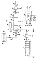
- Figure 1 shows a schematic representation of the exhaust pipe 2 of a 300 kW charge air-cooled diesel engine 4 with a measuring point 5 connected to the diesel engine 4.
- a further measuring point 6 a catalyst unit 8 and an additional measuring point 20 are installed in sequence.
- the catalyst unit 8 comprises an inlet chamber 12, one in turn Hydrolysis catalytic converter 14, a DeNO x catalytic converter 16 and an oxidation catalytic converter 18.
- a blue burner exhaust pipe 22 and a reducing agent supply pipe 32 with an adjustable injection valve 24 for the controlled addition of a reducing agent 26 are connected to the inlet chamber 12 of the catalytic converter unit 8.
- hot exhaust gas 36 from a blue burner 28 is introduced into the inlet chamber 12 via the blue burner exhaust line 22.
- the reducing agent 26, in the exemplary embodiment an aqueous urea solution, is stored in a reducing agent tank 30 and fed to the injection valve 24 via the reducing agent supply line 32.
- the injection valve 24 By means of the injection valve 24, the reducing agent 26 is injected into the inlet chamber 12 within a zone which is delimited by perforated plates 34 against the walls of the inlet chamber 12.
- the exhaust gas 10 and possibly the blue burner exhaust gas 36 enter the inlet chamber 12 outside this zone; they penetrate the holes in the perforated plates 34 and thereby take the reducing agent 26 injected into the inlet chamber 12 with them. This prevents the reducing agent 26 from depositing disadvantageously on the walls of the inlet chamber 12.
- a control unit 38 with a microprocessor sub-unit 40 is provided for setting the reducing agent rate M R metered into the exhaust gas 10. Via inputs E 1 to E 4, the control unit 38 detects operationally relevant parameters, the knowledge of which is necessary for setting the suitable reducing agent rate M R. By means of the measuring point 5, which comprises a series of sensors, the air mass flow, the control rod path, which corresponds to the position of the diesel injector, the boost pressure and the speed of the diesel engine 4 are detected. This data is available at input E 1 .
- the mass flow and the pressure from the am Input E 1 existing parameters of the diesel engine 4 are calculated. It would also be possible to measure the pressure and also the mass flow via separate sensors in the further measuring point 6.
- the temperature of the exhaust gas 10 measured by means of the additional measuring point 20 downstream of the catalyst unit 8 is present at the input E 3 .
- the input-relevant parameters of the catalyst unit 8 are present at the input E 4 , namely their catalytic activity and their pressure and temperature profile, their specific storage capacity C R for the reducing agent 26 and their pressure and temperature profile and their physical size, such as the catalytic weight active mass, geometry and heat transfer. These parameters can be stored, for example, on an accessory diskette 44 as a supplement to the catalyst unit 8. They can be loaded (implemented) into the microprocessor sub-unit 40 by means of a floppy disk drive 42, which is installed in the control unit 38.
- the injection valve 24 for the reducing agent 26 is controlled and thus adjusted via an output A 1 .
- the setting of the reducing agent rate M R metered into the exhaust gas 10 by means of the injection valve 24 takes place as a function of the operationally relevant parameters of the engine 4, the exhaust gas 10 and the catalytic converter 8, which will be explained in more detail below.
- the blue burner 28 can be switched on and off as required via an output A 2 .
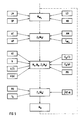
- a flow chart for determining the reducing agent rate M R is shown in FIG. 5.
- the control unit 38 first determines the nitrogen oxide content in the exhaust gas 10 by detecting the parameters measured by the measuring point 5. This takes place in particular in the microprocessor subunit 40 which, by comparing the characteristics of the parameters air mass flow LM, control rod travel GP, boost pressure LD and engine speed MD, the nitrogen oxide rate M NO x determined in terms of hardware or software, as described, for example, in DE-OS 36 15 021.
- the temperature KT of the catalyst unit 8 is determined by means of the control unit 38, for example computationally by averaging or by integrating the differential equation for the heat transfer of the catalyst unit 8.
- this second intermediate value Z 2 (M R ) is reduced in accordance with the decrease in the catalytic activity k (cf. FIG. 2).
- This adaptation of the second intermediate value is overlaid with the adaptation to the pressure profile of the catalytic activity.
- the pressure curve increases with increasing absolute pressure on the catalytic converter.
- the dosing of the reducing agent 26 in the event of a positive load jump takes place already when the control rod travel GP (accelerator pedal) is increased passed) without waiting for an increase in the temperature T at the catalyst unit 8.
- the expected temperature increase is calculated in advance on the basis of the operationally relevant data by means of the control unit 38.
- the reducing agent 26 introduced into the inlet chamber by means of the injection valve 24 is guided into the hydrolysis catalytic converter 14 by means of the exhaust gas 10.
- the aqueous urea solution used in the exemplary embodiment hydrolyzes to ammonia, carbon dioxide and water.
- the hydrolysis is caused by precious metal constituents contained in the hydrolysis catalyst 14 and the elevated temperature prevailing there.
- the nitrogen oxides are converted to nitrogen and water together with the ammonia by contacting the catalytically active material of the DeNO x catalyst 16.
- the hydrocarbons are already largely catalytically converted at temperatures above 300 ° C.
- Another step for determining the reducing agent rate M R can optionally be carried out.
- a qualitative course of the catalytic activity k shown in FIG. 4 depending on the total operating time t B is shown in the exemplary embodiment, for example via the operationally relevant parameters of the catalytic converter unit 8 implemented and taken into account in the control unit 38.
- the nitrogen oxide rate M NO x reducing agent rate M R metered into the exhaust gas, ie initially the second intermediate value Z 2 (M R ) is reduced with increasing total operating time t B.
- a third intermediate value Z 3 (M R ) derived from the second intermediate value Z 2 (M R ) can additionally or alternatively correspond to that with the operating time t B evaluated exhaust gas temperatures can be determined on the catalyst unit 8, which is reduced compared to the second intermediate value Z 2 (M R ).
- the microprocessor subunit 40 can, for example, calculate the integral over the time profile of the temperature KT on the catalyst unit 8.
- the catalyst parameters can be checked and, if necessary, corrected. If a specified limit value is undershot, a request to replace the catalyst unit 8 can also be reported.
- a further correction of the third intermediate value Z 3 (M R ) that is formed is optionally carried out in the exemplary embodiment by taking into account the space velocity RG of the exhaust gas 10 in the catalyst unit 8.
- the catalyst unit 8 is at a maximum space velocity RG max , which is derived on the basis of its geometry, designed. If this maximum exhaust gas space velocity in the catalytic converter unit 8 is exceeded, the third intermediate value Z 3 (M R ) is then reduced, thereby preventing the reducing agent 26 with the exhaust gas 10 from being "blown through” through the catalytic converter unit 8 and consequently resulting in undesirable ammonia slip. This reduction can be carried out, for example, according to the ratio of the maximum space velocity to the currently prevailing exhaust gas space velocity.
- reducing agent rate M R metered into the exhaust gas 10 is set to zero when the temperature AT of the exhaust gas falls below a temperature T min according to FIG. 2 or exceeds a temperature T max according to FIG. It depends on the pressure and temperature profile of the catalytic activity k of the catalyst unit 8 used, at what temperature T min and at what temperature T max .
- the DeNO x catalyst 16 selected in the exemplary embodiment its catalytically active substance titanium oxide TiO 2 and one or more of the additives V x Mo y O 32-z with x, y ⁇ 1; x + y ⁇ 12 and z ⁇ 1, tungsten oxide WO 3 , molybdenum oxide MO 3 and vanadium oxide V 2 O 5 , the temperature T min is about 240 ° C and the temperature T max is about 550 ° C. Within this temperature window ammonia slip and undesirable reactions of the ammonia with sulfur oxides contained in the exhaust gas and the formation of undesirable nitrogen compounds, such as laughing gas N 2 O, are particularly well avoided.
- the exhaust gas 10 can at least partially be recirculated into the intake air of the diesel engine 4 after passing through a charging turbine of a turbocharger (not shown here).
- means for cooling the exhaust gas can be switched on, which cause the temperature of the exhaust gas 10 to drop below the temperature T max again.
- This can be effected, for example, by introducing the exhaust gas 10 into a cooling section (not shown here), for example an air / air heat exchanger, or by switching on an airflow cooling system for a section of the exhaust gas line 2 and / or by injecting water into the exhaust gas 10.
- the catalytic converter unit 8 is free of reducing agents 26 and hydrocarbons before the diesel engine 4 is started up. At the same time, this increases the safety margin that can be used when the reducing agent 26 is metered in to avoid slipping of the reducing agent.
- This “emptying” of the catalytic converter unit 8 can be carried out, for example, by briefly idling operation following the use mode with the blue burner 28 switched on and / or by switching the blue burner 28 on before starting the diesel engine 4.
- the method carried out according to FIG. 5 for determining the reducing agent rate M R can be carried out by means of the known control units, e.g. B. Hybrid-based computers can be performed several times per second.
- the measuring point 6 is equipped with a sensor for measuring the nitrogen oxide concentration and the volume flow of the exhaust gas 10
- the construction compared to FIG. 1 is simpler. Because the nitrogen oxide rate M NO x is now determined directly from the volume flow and the nitrogen oxide concentration of the exhaust gas 10, it is now only necessary to record the air mass flow of the diesel engine 4 via the input E 1 . However, the method explained with reference to FIG. 1 and the device for metering the reducing agent 26 into the nitrogen oxide-containing exhaust gas 10 of the diesel engine 4 shown in FIG. 1 remain otherwise unchanged.
- the setting of the reducing agent rate M R becomes almost trivial if the measuring points 6 and 20 comprise sensors for measuring the nitrogen oxide or nitrogen oxide and reducing agent concentration.
- the reducing agent rate M R can then be set on the basis of the nitrogen oxide concentration in the exhaust gas 10 and readjusted by means of the nitrogen oxide and reducing agent concentration in the exhaust gas 10 measured with the measuring point 20 behind the catalytic converter 8 by means of the control unit 38, for example in the millisecond range.
Landscapes
- Engineering & Computer Science (AREA)
- Chemical & Material Sciences (AREA)
- Chemical Kinetics & Catalysis (AREA)
- Combustion & Propulsion (AREA)
- Health & Medical Sciences (AREA)
- Mechanical Engineering (AREA)
- General Engineering & Computer Science (AREA)
- Analytical Chemistry (AREA)
- Oil, Petroleum & Natural Gas (AREA)
- General Chemical & Material Sciences (AREA)
- Environmental & Geological Engineering (AREA)
- Biomedical Technology (AREA)
- Materials Engineering (AREA)
- Toxicology (AREA)
- Exhaust Gas After Treatment (AREA)
- Treating Waste Gases (AREA)
Claims (18)
- Procédé d'apport régulé d'un agent réducteur (26) à un gaz d'échappement (10) contenant des oxydes d'azote d'un moteur (4) à combustion interne, comportant une unité de catalyseur (8) qui est montée dans un conduit (2) pour le gaz d'échappement et qui est destinée à diminuer la teneur en oxyde d'azote, dans lequel au moins un paramètre du gaz d'échappement (10) qui est pertinent du point de vue du fonctionnement, au moins un paramètre de l'unité de catalyseur (8) qui est pertinent du point de vue du fonctionnement, et le cas échéant au moins un paramètre du moteur (4) qui est pertinent du point de vue du fonctionnement sont détectés pour déterminer le taux d'oxyde d'azote MNOx, caractérisé en ce qu'il consiste à déterminer en fonction du taux d'oxyde d'azote MNOx une valeur intermédiaire Z1(ṀR) pour le taux d'agent réducteur ṀR qui est diminuée d'un taux d'agent réducteur ṀD désorbé de l'unité de catalyseur (8) ou qui est augmentée d'un taux d'agent réducteur ṀA adsorbé par l'unité de catalyseur (8).
- Procédé suivant la revendication 1,
caractérisé en ce que l'on tient compte lors de la détermination du taux d'agent réducteur ṀD désorbé et du taux d'agent réducteur ṀA adsorbé, du fait que la capacité spécifique CR d'emmagasinage de l'agent réducteur diminue lorsque la température du gaz d'échappement s'élève et augmente lorsque la pression du gaz d'échappement augmente. - Procédé suivant la revendication 1 ou 2,
caractérisé en ce que la diminution a lieu déjà pour une variation dans le temps du trajet de la tige de réglage qui provoque un saut positif de charge en fonction d'un calcul préalable de la température T du catalyseur (8). - Procédé suivant l'une des revendications 1 à 3,
caractérisé en ce que l'augmentation a lieu déjà pour un abaissement de température ayant lieu effectivement sur l'unité de catalyseur (8). - Procédé suivant l'une des revendications 1 à 4,
caractérisé en ce que la valeur intermédiaire Z1(ṀR) diminue lorsque la température du gaz d'échappement s'abaisse et augmente lorsque la température du gaz d'échappement s'élève, si la température du gaz. d'échappement sur l'unité de catalyseur (8) est plus basse qu'une température T(kmax) pour laquelle l'unité de catalyseur (8) présente une activité catalytique maximum kmax. - Procédé suivant l'une des revendications 1 à 5,
caractérisé en ce que la valeur intermédiaire Z1(ṀR) diminue lorsque la température du gaz d'échappement s'élève et augmente lorsque la température du gaz d'échappement s'abaisse, si la température du gaz d'échappement sur l'unité de catalyseur (8) est plus haute qu'une température T(kmax) pour laquelle l'unité de catalyseur (8) présente une activité catalytique maximum kmax. - Procédé suivant l'une des revendications 1 à 6,
caractérisé en ce que la valeur intermédiaire diminue lorsque l'on dépasse une vitesse spatiale pour laquelle l'unité de catalyseur (8) est conçue. - Procédé suivant l'une des revendications 1 à 7,
caractérisé en ce que la valeur intermédiaire diminue lorsque la durée de fonctionnement tB augmente. - Procédé suivant la revendication 8,
caractérisé en ce que la valeur intermédiaire diminue en fonction des températures du gaz d'échappement sur l'unité de catalyseur (8) pondérées par la durée de fonctionnement tB. - Procédé suivant l'une des revendications 1 à 9,
caractérisé en ce que l'unité de catalyseur (8) est, avant la mise en fonctionnement du moteur à combustion interne (4), débarrassée par combustion avec évaporation de l'agent réducteur (26) et des hydrocarbures. - Procédé suivant l'une des revendications 1 à 10,
caractérisé en ce qu'il est prévu comme paramètre du moteur (4) qui est pertinent du point de vue du fonctionnement le courant massique d'air (LM), le trajet de la tige de réglage (GP) correspondant au dispositif d'injection de carburant, la pression de suralimentation (LD) et/ou le régime (MD) du moteur. - Procédé suivant l'une des revendications 1 à 11,
caractérisé en ce qu'il est prévu comme paramètre du gaz d'échappement (10) qui est pertinent du point de vue du fonctionnement sa température (AT), sa pression (AP), son courant massique (AM) et sa concentration en oxyde d'azote (CNOx) , et cela de préférence tous ensemble. - Procédé suivant l'une des revendications 1 à 12,
caractérisé en ce qu'il est prévu comme paramètre de l'unité de catalyseur (8) qui est pertinent du point de vue du fonctionnement sa température (KT), son activité catalytique (k) avec sa courbe de pression et de température (k(p) et k(T)), sa capacité d'emmagasinage CR spécifique de l'agent réducteur (26) avec sa courbe de pression de température (CR(p) et CR(T)) et ses grandeurs physiques, comme par exemple le poids de la masse catalytiquement active, la géométrie et la transmission de chaleur, et cela de préférence tous ensemble. - Dispositif d'apport commandé d'un agent réducteur (26) au gaz d'échappement (10) contenant de l'oxyde d'azote d'un moteur à combustion interne (4) ayant une unité de catalyseur (8) montée dans le conduit (2) pour les gaz d'échappement en vue de diminuer les oxydes d'azote, ce dispositif étant destiné à la mise en oeuvre du procédé suivant l'une des revendication 1 à 13, caractérisé en ce qu'il est prévue une unité de contrôle (38), des moyens (5, 6, 20, 42, 44) associés à cette unité de contrôle (38) et destinée à détecter au moins un paramètre du gaz d'échappement (10) qui est pertinent du point de vue du fonctionnement, au moins un paramètre de l'unité catalyseur (8) qui est pertinent du point de vue du fonctionnement et le cas échéant au moins un paramètre du moteur (4) qui est pertinent au point de vue du fonctionnement, et une unité d'amenée d'agent réducteur (24, 30, 32) associée à l'unité de commande (38), et par laquelle un agent réducteur (26) peut être amené en amont dans le sens d'écoulement du gaz d'échappement (10) de l'unité de catalyseur (8) dans le conduit (2) pour le gaz d'échappement, l'unité de contrôle (38) étant prévue pour régler en fonction des paramètres qui sont pertinents du point de vue du fonctionnement, le taux d'agent réduction ṀR introduit dans le gaz d'échappement (10), et cela en tenant compte d'un taux ṀA d'agent réducteur adsorbé par l'unité de catalyseur (8) ou d'un taux d'agent réducteur ṀD désorbé par l'unité de catalyseur (8).
- Dispositif suivant la revendication 14,
caractérisé en ce que l'unité de catalyseur (8) comprend successivement dans le sens d'écoulement du gaz d'échappement (10) un catalyseur (14) d'hydrolyse, un catalyseur (16) DeNOx et le cas échéant un catalyseur (18) d'oxydation. - Dispositif suivant la revendication 14 ou 15,
caractérisé en ce que l'unité d'apport d'agent réducteur (24, 30, 32) comporte une vanne (34) d'injection de l'agent réducteur (26), de préférence une solution aqueuse, qui peut être réglée par l'unité de contrôle (38). - Dispositif suivant l'une des revendications 14 à16,
caractérisé en ce que l'unité de contrôle (38) comporte une mémoire pour tous les paramètres possibles du gaz d'échappement (10), de l'unité de catalyseur (8) et le cas échéant du moteur (4) qui sont pertinents du point de vue du fonctionnement pour la détermination du taux d'agent réducteur ṀR et en ce que les moyens (5, 6, 20, 42, 44) interrogent par leurs signaux une valeur de mémoire adéquate pour le taux d'agent réducteur ṀR, la valeur en mémoire s'appliquant à une sortie (A1) de l'unité de contrôle (38) pour commander l'unité d'envoi d'agent réducteur (24, 30, 32). - Dispositif suivant l'une des revendications 14 à 16,
caractérisé en ce que l'unité de contrôle (38) comprend une sous-unité (40) à microprocesseur qui, au moyen d'un programme, détermine le taux d'agent réducteur ṀR à partir des paramètres du gaz d'échappement (10), de l'unité de catalyseur (8) et, le cas échéant, du moteur qui sont pertinents du point de vue du fonctionnement et qui sont déterminés à l'aide des moyens (5, 6, 20, 42, 44).
Applications Claiming Priority (3)
| Application Number | Priority Date | Filing Date | Title |
|---|---|---|---|
| DE4315278A DE4315278A1 (de) | 1993-05-07 | 1993-05-07 | Verfahren und Einrichtung zur Dosierung eines Reduktionsmittels in ein stickoxidhaltiges Abgas |
| DE4315278 | 1993-05-07 | ||
| PCT/DE1994/000463 WO1994027035A1 (fr) | 1993-05-07 | 1994-04-27 | Procede et dispositif permettant l'apport regule d'un agent reducteur dans des gaz d'echappement contenant de l'oxyde nitrique |
Publications (2)
| Publication Number | Publication Date |
|---|---|
| EP0697062A1 EP0697062A1 (fr) | 1996-02-21 |
| EP0697062B1 true EP0697062B1 (fr) | 1996-09-25 |
Family
ID=6487516
Family Applications (1)
| Application Number | Title | Priority Date | Filing Date |
|---|---|---|---|
| EP94913016A Expired - Lifetime EP0697062B1 (fr) | 1993-05-07 | 1994-04-27 | Procede et dispositif permettant l'apport regule d'un agent reducteur dans des gaz d'echappement contenant de l'oxyde nitrique |
Country Status (7)
| Country | Link |
|---|---|
| US (1) | US5628186A (fr) |
| EP (1) | EP0697062B1 (fr) |
| JP (1) | JP3342014B2 (fr) |
| AT (1) | ATE143460T1 (fr) |
| DE (2) | DE4315278A1 (fr) |
| ES (1) | ES2091694T3 (fr) |
| WO (1) | WO1994027035A1 (fr) |
Cited By (6)
| Publication number | Priority date | Publication date | Assignee | Title |
|---|---|---|---|---|
| WO1998035143A1 (fr) * | 1997-02-06 | 1998-08-13 | Siemens Aktiengesellschaft | Procede et dispositif de commande d'une systeme de combustion, epuration catalytique des gaz d'echappement et systeme de combustion |
| WO1999049956A1 (fr) * | 1998-03-31 | 1999-10-07 | Siemens Aktiengesellschaft | Procede et dispositif de suppression catalytique d'un polluant contenu dans les gaz d'echappement d'une installation a combustion interne |
| US6119448A (en) * | 1997-08-21 | 2000-09-19 | Man Nutzfahrzeuge Ag | Method for metering a reducing agent into NOx -containing exhaust gas of an internal combustion engine |
| FR2872544A1 (fr) | 2004-06-30 | 2006-01-06 | Bosch Gmbh Robert | Procede de gestion d'un catalyseur utilise pour nettoyer les gaz d'echappement d'un moteur a combustion interne et dispositif pour la mise en oeuvre du procede |
| DE10163006B4 (de) * | 2000-12-21 | 2010-06-24 | Toyota Jidosha Kabushiki Kaisha, Toyota-shi | Vorrichtung und Verfahren zur Abgasreinigung für einen Verbrennungsmotor |
| US8196390B2 (en) | 2005-12-23 | 2012-06-12 | Robert Bosch Gmbh | Procedure and device to monitor an exhaust gas after-treatment system |
Families Citing this family (186)
| Publication number | Priority date | Publication date | Assignee | Title |
|---|---|---|---|---|
| EP0652435A3 (fr) * | 1993-11-04 | 1996-11-20 | Siemens Ag | Détecteur pour déterminer le gradient d'une concentration. |
| DE59503286D1 (de) * | 1994-08-10 | 1998-09-24 | Siemens Ag | Verfahren zur katalytischen umsetzung von im abgas eines verbrennungsmotors enthaltenen stickoxiden |
| US5943858A (en) * | 1995-05-19 | 1999-08-31 | Siemens Aktiengesellschaft | Premixing chamber for an exhaust gas purification system |
| JPH0913955A (ja) * | 1995-06-27 | 1997-01-14 | Komatsu Ltd | ディーゼルエンジンの排気ガス浄化装置 |
| DE19531028A1 (de) * | 1995-08-23 | 1997-02-27 | Siemens Ag | Verfahren zur Abgasreinigung und Abgas-Reinigungseinrichtung für einen Verbrennungsmotor |
| DE19536571C2 (de) * | 1995-09-29 | 1998-09-03 | Siemens Ag | Verfahren sowie Vorrichtung zur Dosierung der Eingabe eines Reduktionsmittels in den Abgas- oder Abluftstrom einer Verbrennungsanlage |
| ES2129993T3 (es) * | 1995-09-29 | 1999-06-16 | Siemens Ag | Procedimiento y dispositivo para la conversion de una substancia contaminante en un gas de escape en un catalizador. |
| US6345496B1 (en) | 1995-11-09 | 2002-02-12 | Toyota Jidosha Kabushiki Kaisha | Method and device for purifying exhaust gas of an engine |
| KR100287051B1 (ko) * | 1995-11-17 | 2001-09-07 | 와다 아끼히로 | 엔진의 배기가스 정화 방법 및 장치 |
| DE19545169A1 (de) * | 1995-12-04 | 1997-06-05 | Bayerische Motoren Werke Ag | Verfahren zur Funktionsüberwachung eines HC-Adsorbers |
| JP3713831B2 (ja) * | 1996-04-19 | 2005-11-09 | トヨタ自動車株式会社 | 内燃機関の排気浄化装置 |
| JP3454334B2 (ja) * | 1996-06-18 | 2003-10-06 | トヨタ自動車株式会社 | 排気浄化方法及びその装置 |
| DE19629163C1 (de) * | 1996-07-19 | 1997-10-09 | Daimler Benz Ag | Verfahren und Vorrichtung zum stickoxidemissionsarmen Betrieb eines Verbrennungsmotors |
| DE19646646C2 (de) * | 1996-11-12 | 1998-12-10 | Daimler Benz Ag | Verfahren und Vorrichtung zur Stickoxidreduktionsmittelzudosierung zum Abgas einer Verbrennungsanlage |
| US6361754B1 (en) * | 1997-03-27 | 2002-03-26 | Clean Diesel Technologies, Inc. | Reducing no emissions from an engine by on-demand generation of ammonia for selective catalytic reduction |
| US5924280A (en) * | 1997-04-04 | 1999-07-20 | Clean Diesel Technologies, Inc. | Reducing NOx emissions from an engine while maximizing fuel economy |
| DE19721440A1 (de) * | 1997-05-21 | 1998-11-26 | Degussa | Verfahren zur Reinigung eines mageren Abgases und Katalysatorsystem hierfür |
| DE19726392A1 (de) * | 1997-06-21 | 1998-12-24 | Bosch Gmbh Robert | Gemischabgabevorrichtung |
| DE19731865C2 (de) * | 1997-07-24 | 1999-05-06 | Siemens Ag | Abgasreinigungsanlage für das Abgas eines Dieselmotors |
| US6003305A (en) | 1997-09-02 | 1999-12-21 | Thermatrix, Inc. | Method of reducing internal combustion engine emissions, and system for same |
| US5989010A (en) | 1997-09-02 | 1999-11-23 | Thermatrix, Inc. | Matrix bed for generating non-planar reaction wave fronts, and method thereof |
| DE19738859A1 (de) * | 1997-09-05 | 1999-03-11 | Bosch Gmbh Robert | Gemischabgabevorrichtung |
| DE19749400C2 (de) | 1997-11-07 | 2001-11-29 | Siemens Ag | Verfahren zur Verringerung des NOX-Gehaltes im Abgas einer Dieselbrennkraftmaschine |
| DE19749607C1 (de) * | 1997-11-10 | 1999-03-18 | Siemens Ag | Verfahren und Einrichtung zur Verminderung der Anzahl von Partikeln in einem Abgas |
| DE19756251C1 (de) * | 1997-12-17 | 1999-07-22 | Siemens Ag | Verfahren und Vorrichtung zur Reduzierung der Stickoxide im Abgas einer Verbrennungsanlage |
| US8833062B1 (en) | 2013-03-15 | 2014-09-16 | Daimier Ag | Catalytic reduction of NOx |
| GB9802504D0 (en) | 1998-02-06 | 1998-04-01 | Johnson Matthey Plc | Improvements in emission control |
| DE19807935C1 (de) | 1998-02-25 | 1999-08-26 | Siemens Ag | Vorrichtung zur Reduzierung des NO¶x¶-Gehaltes im Abgas einer Brennkraftmaschine |
| DE19811257A1 (de) * | 1998-03-14 | 1999-09-16 | Volkswagen Ag | Verfahren zur Steuerung der Abgasnachbehandlung eines DI-Otto- und Magermotors |
| DE19817994A1 (de) * | 1998-04-22 | 1999-11-04 | Emitec Emissionstechnologie | Verfahren und Vorrichtung zur Reinigung von Stickoxid (NO¶x¶) enthaltendem Abgas eines Verbrennungsmotors |
| DE19818448A1 (de) | 1998-04-24 | 1999-10-28 | Siemens Ag | Verfahren und Vorrichtung zur katalytischen Reduzierung von Stickoxiden im Abgas einer Verbrennungsanlage |
| GB9808876D0 (en) | 1998-04-28 | 1998-06-24 | Johnson Matthey Plc | Combatting air pollution |
| DE19824915C1 (de) * | 1998-06-04 | 1999-02-18 | Daimler Benz Ag | Verfahren zum Wechseln der Betriebsart einer direkt-einspritzenden Otto-Brennkraftmaschine |
| JP2001303934A (ja) * | 1998-06-23 | 2001-10-31 | Toyota Motor Corp | 内燃機関の排気浄化装置 |
| JP4280335B2 (ja) * | 1998-08-26 | 2009-06-17 | エム アー エヌ ヌツツフアールツオイゲ アクチエンゲゼルシヤフト | 内燃機関の窒素含有排ガス中への還元剤の供給方法 |
| DE19840404A1 (de) | 1998-09-04 | 2000-03-09 | Siemens Ag | Verfahren zur katalytischen Entfernung von polyzyklischen aromatischen Nitro-, Nitroso- und/oder Amino-Verbindungen |
| DE19843136A1 (de) * | 1998-09-21 | 2000-03-30 | Siemens Ag | Abgasreinigungsanlage und Verfahren zur katalytischen Verringerung des Schadstoffgehalts im Abgas einer Verbrennungsanlage |
| DE19843423A1 (de) * | 1998-09-22 | 2000-03-30 | Siemens Ag | Verfahren und Vorrichtung zur katalytischen Beseitigung eines Schadstoffes aus dem Abgas einer Verbrennungsanlage |
| DE19843960A1 (de) * | 1998-09-24 | 2000-03-30 | Siemens Ag | Verfahren und Vorrichtung zur katalytischen Verringerung des Schadstoffgehalts im Abgas einer Verbrennungsanlage |
| US6125629A (en) * | 1998-11-13 | 2000-10-03 | Engelhard Corporation | Staged reductant injection for improved NOx reduction |
| FR2787037B1 (fr) * | 1998-12-09 | 2002-01-11 | Inst Francais Du Petrole | Procede et dispositif d'elimination des oxydes d'azote dans une ligne d'echappement de moteur a combustion interne |
| DE19901915C1 (de) * | 1999-01-19 | 2000-04-20 | Siemens Ag | Verfahren zur katalytischen Umsetzung von im Abgas eines Verbrennungsmotors enthaltenen Stickoxiden |
| EP1033480A1 (fr) * | 1999-02-17 | 2000-09-06 | Man Nutzfahrzeuge Ag | Procédé de dosage d'un agent de réduction dans le gaz d'échappement d'un moteur à combustion interne contenant de l'oxyde d'azote |
| DE19919472C2 (de) * | 1999-04-29 | 2001-04-19 | Bosch Gmbh Robert | Vorrichtung und Verfahren zur Detektion von Ammoniak |
| DE19922959A1 (de) | 1999-05-19 | 2000-11-23 | Daimler Chrysler Ag | Abgasreinigungsanlage mit Stickoxidreduktion unter Reduktionsmittelzugabe |
| DE19924029C2 (de) * | 1999-05-26 | 2001-05-23 | Porsche Ag | Verfahren zur Überwachung der Funktion eines Systems zur Abgasnachbehandlung |
| US6182444B1 (en) | 1999-06-07 | 2001-02-06 | Ford Global Technologies, Inc. | Emission control system |
| DE19929935A1 (de) * | 1999-06-29 | 2000-07-27 | Siemens Ag | Einrichtung zur Entstickung von Abgas |
| US6295809B1 (en) | 1999-07-12 | 2001-10-02 | Ford Global Technologies, Inc. | Emission control system with a catalyst |
| US6293097B1 (en) * | 1999-08-16 | 2001-09-25 | Ford Global Technologies, Inc. | On-board reductant delivery system |
| US6266955B1 (en) | 1999-08-20 | 2001-07-31 | Caterpillar Inc. | Diagnostic system for an emissions control on an engine |
| US6237326B1 (en) * | 1999-08-24 | 2001-05-29 | Ford Global Technolgies, Inc. | Engine control system and method with lean catalyst and particulate filter |
| US6253543B1 (en) * | 1999-08-24 | 2001-07-03 | Ford Global Technologies, Inc. | Lean catalyst and particulate filter control |
| DE19944009A1 (de) * | 1999-09-14 | 2001-03-22 | Siemens Ag | Verfahren zum Betrieb eines SCR-Katalysators |
| US6354079B1 (en) * | 1999-11-26 | 2002-03-12 | Hyundai Motor Company | Apparatus and method of purifying NOx in the exhaust gas of the diesel engine |
| US6311484B1 (en) | 2000-02-22 | 2001-11-06 | Engelhard Corporation | System for reducing NOx transient emission |
| US6269633B1 (en) | 2000-03-08 | 2001-08-07 | Ford Global Technologies, Inc. | Emission control system |
| JP2001276564A (ja) * | 2000-03-30 | 2001-10-09 | Miura Co Ltd | ボイラの脱硝装置 |
| US6427439B1 (en) | 2000-07-13 | 2002-08-06 | Ford Global Technologies, Inc. | Method and system for NOx reduction |
| US6408616B1 (en) * | 2000-07-20 | 2002-06-25 | Ford Global Technologies, Inc. | Diesel OBD-II system for detection of degradation of catalyst activity |
| JP3613676B2 (ja) * | 2000-07-24 | 2005-01-26 | トヨタ自動車株式会社 | 内燃機関の排気浄化装置 |
| DE10038741A1 (de) * | 2000-08-09 | 2002-02-21 | Porsche Ag | Verfahren und Vorrichtung zur Zuführung eines Reduktionsmittels in eine Katalysatoreinrichtung |
| DE10047519A1 (de) * | 2000-09-22 | 2002-04-18 | Bosch Gmbh Robert | Verfahren und Vorrichtung zur Dosierung eines Reduktionsmittels zur Entfernung von Stickoxiden aus Abgasen |
| US6415602B1 (en) | 2000-10-16 | 2002-07-09 | Engelhard Corporation | Control system for mobile NOx SCR applications |
| JP3719127B2 (ja) * | 2000-10-25 | 2005-11-24 | トヨタ自動車株式会社 | NOx排出抑止型ハイブリッド車 |
| JP3982178B2 (ja) | 2000-10-27 | 2007-09-26 | トヨタ自動車株式会社 | 有害ガス成分排出抑制型車輌 |
| JP3794468B2 (ja) * | 2000-12-19 | 2006-07-05 | 三菱電機株式会社 | 内燃機関の排気ガス浄化装置 |
| DE10100420A1 (de) * | 2001-01-08 | 2002-07-11 | Bosch Gmbh Robert | Verfahren und Vorrichtung zur Steuerung eines Abgasnachbehandlungssystems |
| DE10100419A1 (de) * | 2001-01-08 | 2002-07-11 | Bosch Gmbh Robert | Verfahren und Vorrichtung zur Steuerung eines Abgasnachbehandlungssystems |
| DE10103771A1 (de) * | 2001-01-27 | 2002-08-14 | Omg Ag & Co Kg | Verfahren zur Wiederherstellung der katalytischen Aktivität eines Katalysators, welcher im Abgastrakt eines Dieselmotors angeordnet ist und wenigstens eine Oxidationsfunktion aufweist |
| US6449945B1 (en) | 2001-04-18 | 2002-09-17 | Ford Global Technologies, Inc. | Emission control system |
| US6421599B1 (en) | 2001-08-09 | 2002-07-16 | Ford Global Technologies, Inc. | Control strategy for an internal combustion engine in a hybrid vehicle |
| US6928359B2 (en) * | 2001-08-09 | 2005-08-09 | Ford Global Technologies, Llc | High efficiency conversion of nitrogen oxides in an exhaust aftertreatment device at low temperature |
| US6698191B2 (en) * | 2001-08-09 | 2004-03-02 | Ford Global Technologies, Llc | High efficiency conversion of nitrogen oxides in an exhaust aftertreatment device at low temperature |
| US6742326B2 (en) | 2001-08-09 | 2004-06-01 | Ford Global Technologies, Llc | High efficiency conversion of nitrogen oxides in an exhaust aftertreatment device at low temperature |
| US6487852B1 (en) | 2001-09-04 | 2002-12-03 | Ford Global Technologies, Inc. | Method and apparatus for controlling reactant injection into an active lean NOx catalyst |
| US6546720B2 (en) | 2001-09-04 | 2003-04-15 | Ford Global Technologies, Inc. | Method and apparatus for controlling the amount of reactant to be added to a substance using a sensor which is responsive to both the reactant and the substance |
| US7121085B2 (en) | 2001-09-04 | 2006-10-17 | Ford Global Technologies, Llc | Method and apparatus for controlling hydrocarbon injection into engine exhaust to reduce NOx |
| DE10207984A1 (de) * | 2002-02-25 | 2003-10-23 | Daimler Chrysler Ag | Vorrichtung zur Abgasreinigung und Verfahren hierzu |
| JP3951774B2 (ja) * | 2002-03-29 | 2007-08-01 | 三菱ふそうトラック・バス株式会社 | 内燃機関のNОx浄化装置 |
| EP1492945A1 (fr) | 2002-04-05 | 2005-01-05 | E. I. du Pont de Nemours and Company | Procede et appareil destines a reguler un processus d'emission de gaz et dispositifs associes |
| US7497076B2 (en) * | 2002-05-07 | 2009-03-03 | Extengine Transport Systems | Emission control system |
| US7065958B2 (en) * | 2002-05-07 | 2006-06-27 | Extengine Transport Systems | Emission control system |
| DE10227026A1 (de) * | 2002-06-17 | 2004-03-18 | Abb Research Ltd. | Verfahren und Vorrichtung zur Regelung einer Rauchgasentstickungsanlage |
| US20040126286A1 (en) * | 2002-06-19 | 2004-07-01 | Deruyter John C. | Method and apparatus for reducing a nitrogen oxide |
| US7575931B2 (en) * | 2002-06-19 | 2009-08-18 | E.I. Du Pont De Nemours And Company | Method and apparatus for reducing a nitrogen oxide, and control thereof |
| US6887284B2 (en) * | 2002-07-12 | 2005-05-03 | Dannie B. Hudson | Dual homogenization system and process for fuel oil |
| GB0220645D0 (en) | 2002-09-05 | 2002-10-16 | Johnson Matthey Plc | Exhaust system for a lean burn ic engine |
| US20040057888A1 (en) * | 2002-09-25 | 2004-03-25 | Mitsubishi Power Systmes, Inc. | Ammonia distribution grid for selective catalytic reduction (SCR) system |
| US7166262B2 (en) * | 2002-09-25 | 2007-01-23 | Mitsubishi Power Systems, Inc. | Control for ammonia slip in selective catalytic reduction |
| DE10247989A1 (de) * | 2002-10-15 | 2004-04-29 | Robert Bosch Gmbh | Abgasreinigung einer Brennkraftmaschine und Verfahren zur Reinigung deren Abgase |
| US6993900B2 (en) * | 2002-10-21 | 2006-02-07 | Ford Global Technologies, Llc | Exhaust gas aftertreatment systems |
| DE10251224B4 (de) * | 2002-11-04 | 2005-09-15 | Siemens Ag | Verfahren zur Bestimmung einer Beladung eines Partikelfilters im Abgastrakt einer Brennkraftmaschine |
| US6862879B2 (en) | 2002-11-21 | 2005-03-08 | Ford Global Technologies, Llc | Diesel aftertreatment system |
| US6834498B2 (en) * | 2002-11-21 | 2004-12-28 | Ford Global Technologies, Llc | Diesel aftertreatment systems |
| US7093427B2 (en) * | 2002-11-21 | 2006-08-22 | Ford Global Technologies, Llc | Exhaust gas aftertreatment systems |
| US6941746B2 (en) * | 2002-11-21 | 2005-09-13 | Combustion Components Associates, Inc. | Mobile diesel selective catalytic reduction systems and methods |
| US6895747B2 (en) | 2002-11-21 | 2005-05-24 | Ford Global Technologies, Llc | Diesel aftertreatment systems |
| US6892530B2 (en) * | 2002-11-21 | 2005-05-17 | Ford Global Technologies, Llc | Exhaust gas aftertreatment systems |
| US6761025B1 (en) * | 2002-12-19 | 2004-07-13 | Caterpillar Inc. | Enhanced ammonia feed control for selective catalytic reduction |
| DE10308287B4 (de) * | 2003-02-26 | 2006-11-30 | Umicore Ag & Co. Kg | Verfahren zur Abgasreinigung |
| US6871489B2 (en) * | 2003-04-16 | 2005-03-29 | Arvin Technologies, Inc. | Thermal management of exhaust systems |
| BRPI0411322A (pt) * | 2003-06-12 | 2006-07-18 | Donaldson Co Inc | método de distribuir combustìvel em fluxo transiente de um sistema de descarga |
| DE602004024434D1 (de) * | 2003-09-30 | 2010-01-14 | Nissan Diesel Motor Co | Abgasreinigungsvorrichtung für einen motor |
| SE526404C2 (sv) * | 2004-01-20 | 2005-09-06 | Scania Cv Abp | Förfarande och anordning för styrning av insprutning av reduktionsmedel |
| JP4273011B2 (ja) * | 2004-02-02 | 2009-06-03 | 東京濾器株式会社 | Scrマフラー |
| EP1719884B1 (fr) | 2004-02-02 | 2014-04-02 | Tokyo Roki Co. Ltd. | Bobine coude pour unite canalisee |
| DE102004013164B4 (de) * | 2004-03-17 | 2006-10-12 | GM Global Technology Operations, Inc., Detroit | Katalysator zur Verbesserung der Wirksamkeit der NOx-Reduktion in Kraftfahrzeugen |
| US7776265B2 (en) * | 2004-03-18 | 2010-08-17 | Cummins Filtration Ip, Inc. | System for diagnosing reagent solution quality |
| DE102004018221A1 (de) * | 2004-04-15 | 2005-11-10 | Robert Bosch Gmbh | Verfahren zum Einbringen eines Reagenzmittels in einen Abgaskanal einer Brennkraftmaschine und Vorrichtung zur Durchführung des Verfahrens |
| DE102004021372B4 (de) * | 2004-04-30 | 2014-05-28 | Robert Bosch Gmbh | Verfahren zum Dosieren eines Reagenzmittels zur Reinigung des Abgases von Brennkraftmaschinen und Vorrichtung zur Durchführung des Verfahrens |
| US7784272B2 (en) * | 2004-08-31 | 2010-08-31 | Cummins Inc. | Control system for an engine aftertreatment system |
| JP3969417B2 (ja) * | 2004-10-15 | 2007-09-05 | トヨタ自動車株式会社 | 内燃機関の排気浄化システム。 |
| DE102004051905A1 (de) * | 2004-10-26 | 2006-04-27 | Robert Bosch Gmbh | Vorrichtung und Verfahren zur Erzeugung eines Betriebsmittels für ein Kraftfahrzeug |
| JP2006125247A (ja) * | 2004-10-27 | 2006-05-18 | Hitachi Ltd | エンジンの排気ガス浄化方法及び排気ガス浄化装置 |
| US7644577B2 (en) | 2004-10-29 | 2010-01-12 | Philip Morris Usa, Inc. | Reducing agent metering system for reducing NOx in lean burn internal combustion engines |
| EP1672192B1 (fr) * | 2004-12-18 | 2007-08-08 | Haldor Topsoe A/S | Procédé permettant de commander l'injection d'un agent réducteur dans le gaz d'échappement d'un moteur à combustion interne |
| US7178328B2 (en) * | 2004-12-20 | 2007-02-20 | General Motors Corporation | System for controlling the urea supply to SCR catalysts |
| JP2006242094A (ja) * | 2005-03-03 | 2006-09-14 | Hino Motors Ltd | 排気浄化装置 |
| DE102005015479A1 (de) * | 2005-04-05 | 2006-10-12 | Daimlerchrysler Ag | Vorrichtung und Verfahren zur Abgasnachbehandlung eines Verbrennungsmotors |
| DE102005035554A1 (de) | 2005-07-29 | 2007-02-01 | Emitec Gesellschaft Für Emissionstechnologie Mbh | Verfahren zur selektiven katalytischen Reduktion von Stickoxiden im Abgas einer Verbrennungskraftmaschine und Abgassystem |
| DE102005042487A1 (de) * | 2005-09-07 | 2007-03-08 | Robert Bosch Gmbh | Verfahren zum Betreiben einer Brennkraftmaschine und Vorrichtung zur Durchführung des Verfahrens |
| DE102005048117A1 (de) * | 2005-10-06 | 2007-04-12 | Emitec Gesellschaft Für Emissionstechnologie Mbh | Verfahren und Vorrichtung zur Reduktion des Stickoxidanteils im Abgas einer Verbrennungskraftmaschine |
| DE102005054579A1 (de) * | 2005-11-16 | 2007-05-24 | Robert Bosch Gmbh | Verfahren zum Betreiben einer Abgasbehandlungvorrichtung und Vorrichtung zur Durchführung des Verfahrens |
| US7485272B2 (en) * | 2005-11-30 | 2009-02-03 | Caterpillar Inc. | Multi-stage system for selective catalytic reduction |
| JP4789242B2 (ja) * | 2005-12-09 | 2011-10-12 | Udトラックス株式会社 | 排気浄化装置 |
| US20070137181A1 (en) * | 2005-12-16 | 2007-06-21 | Devesh Upadhyay | Exhaust gas aftertreatment systems |
| US7805929B2 (en) * | 2005-12-21 | 2010-10-05 | Caterpillar Inc | Selective catalytic reduction system |
| JP4432917B2 (ja) * | 2006-03-06 | 2010-03-17 | トヨタ自動車株式会社 | 内燃機関の排気浄化装置 |
| EP2010762B1 (fr) * | 2006-04-13 | 2016-09-28 | Mack Trucks, Inc. | Moteur équipé d'une dispositif de lutte contre les émissions et procédé pour lutter contre les émissions du moteur |
| DE102006025257B4 (de) * | 2006-05-31 | 2016-09-01 | Volkswagen Ag | Verfahren zum Betreiben eines SCR-Katalysators sowie Programmalgorithmus zur Ausführung des Verfahrens |
| EP2029865B1 (fr) | 2006-06-08 | 2010-10-06 | Inergy Automotive Systems Research (Société Anonyme) | Système de stockage d'additif pour gaz d'échappement de moteur |
| JP4513785B2 (ja) * | 2006-06-21 | 2010-07-28 | トヨタ自動車株式会社 | 内燃機関の排気浄化装置 |
| JP5283327B2 (ja) * | 2006-11-10 | 2013-09-04 | 中国電力株式会社 | 脱硝触媒性能試験装置用冷却器 |
| US8240134B2 (en) * | 2006-12-05 | 2012-08-14 | Mack Trucks, Inc. | Engine with exhaust cooling and method |
| US8048390B2 (en) * | 2006-12-23 | 2011-11-01 | Alzchem Trostberg Gmbh | Method for the selective catalytic reduction of nitrogen oxides in exhaust gases of vehicles |
| JP4407705B2 (ja) * | 2007-02-26 | 2010-02-03 | 株式会社デンソー | 排気浄化剤の添加量制御装置、及び排気浄化システム |
| US20080202097A1 (en) * | 2007-02-28 | 2008-08-28 | Caterpillar Inc. | Engine exhaust treatment system |
| JP4710863B2 (ja) | 2007-04-06 | 2011-06-29 | トヨタ自動車株式会社 | 内燃機関の排気浄化装置 |
| US7954312B2 (en) * | 2007-05-09 | 2011-06-07 | Ford Global Technologies, Llc | Approach for detecting reductant availability and make-up |
| US7991533B2 (en) * | 2007-06-11 | 2011-08-02 | Southwest Research Institute | Adaptive reductant dosing and emission control strategies |
| JP4459987B2 (ja) | 2007-06-27 | 2010-04-28 | 株式会社デンソー | 排気浄化剤の添加量制御装置、及び排気浄化システム |
| JP4388103B2 (ja) | 2007-06-27 | 2009-12-24 | 株式会社デンソー | 排気浄化剤の添加量制御装置、及び排気浄化システム |
| JP4877123B2 (ja) * | 2007-07-23 | 2012-02-15 | マツダ株式会社 | エンジンの排気浄化装置 |
| US8001769B2 (en) * | 2007-08-20 | 2011-08-23 | Caterpillar Inc. | Control of SCR system having a filtering device |
| US8713917B2 (en) * | 2007-08-30 | 2014-05-06 | GM Global Technology Operations LLC | Method for reducing NH3 release from SCR catalysts during thermal transients |
| DE102008050357A1 (de) | 2007-10-09 | 2009-04-30 | Mitsubishi Fuso Truck and Bus Corp., Kawasaki | Abgasreinigungseinrichtung für einen Motor |
| JP2009097438A (ja) * | 2007-10-17 | 2009-05-07 | Mitsubishi Fuso Truck & Bus Corp | 排気浄化装置 |
| JP4470987B2 (ja) * | 2007-10-19 | 2010-06-02 | 株式会社デンソー | 還元剤の噴射制御装置 |
| FR2922594A1 (fr) * | 2007-10-23 | 2009-04-24 | Peugeot Citroen Automobiles Sa | Procede de gestion d'injection d'uree dans un systeme a reduction catalytique selective |
| US7987662B2 (en) * | 2007-10-31 | 2011-08-02 | Ford Global Technologies, Llc | Composition and method for controlling excessive exhaust gas temperatures |
| JP4412399B2 (ja) * | 2007-12-06 | 2010-02-10 | トヨタ自動車株式会社 | 内燃機関の異常検出装置 |
| KR100999611B1 (ko) * | 2007-12-14 | 2010-12-08 | 현대자동차주식회사 | 선택적 촉매 환원 장치 내의 암모니아 흡장량 계산 방법 |
| WO2009110102A1 (fr) | 2008-03-04 | 2009-09-11 | トヨタ自動車株式会社 | Système de purification des gaz d'échappement pour moteur à combustion interne |
| US8402755B2 (en) * | 2008-07-30 | 2013-03-26 | General Electric Company | Gas turbine combustor exhaust gas spray cooling for NOx control using selective catalytic reductions |
| DE102008038986A1 (de) * | 2008-08-13 | 2010-02-18 | Emitec Gesellschaft Für Emissionstechnologie Mbh | Verfahren zur geregelten Zugabe eines Reduktionsmittels |
| US8181451B2 (en) * | 2008-11-20 | 2012-05-22 | Alstom Technology Ltd | Method of controlling the operation of a selective catalytic reduction plant |
| US8413424B2 (en) | 2009-01-23 | 2013-04-09 | Caterpillar Inc. | Stored reductant state for startup |
| JP5193355B2 (ja) * | 2009-02-18 | 2013-05-08 | 本田技研工業株式会社 | 内燃機関の排気浄化システム |
| DE102009012092A1 (de) | 2009-03-06 | 2010-09-09 | Man Nutzfahrzeuge Ag | Verfahren zur Anpassung der Dosiermenge eines Reduktionsmittels zur selektiven katalytischen Reduktion |
| DE102009012093A1 (de) | 2009-03-06 | 2010-09-09 | Man Nutzfahrzeuge Ag | Verfahren zur Einstellung der Dosierungen des Reduktionsmittels bei selektiver katalytischer Reduktion |
| US9133749B2 (en) * | 2009-07-10 | 2015-09-15 | Kevin Andrew Gady | Ammonia storage set-point control for selective catalytic reduction applications |
| FR2949353B1 (fr) * | 2009-08-28 | 2012-08-31 | Lab Sa | Procede de determination et de suivi de l'activite d'un catalyseur de denitrification |
| JP2011089434A (ja) * | 2009-10-21 | 2011-05-06 | Toyota Industries Corp | 内燃機関における排気ガス浄化装置 |
| DE102009047070A1 (de) * | 2009-11-24 | 2011-05-26 | Robert Bosch Gmbh | Verfahren zum Betreiben einer Dosiervorrichtung und Vorrichtung zur Durchführung des Verfahrens |
| US8726723B2 (en) | 2010-02-23 | 2014-05-20 | Cummins Emission Solutions | Detection of aftertreatment catalyst degradation |
| US8733083B2 (en) * | 2010-04-26 | 2014-05-27 | Cummins Filtration Ip, Inc. | SCR catalyst ammonia surface coverage estimation and control |
| DE102011103346B4 (de) | 2011-02-16 | 2014-06-26 | Mtu Friedrichshafen Gmbh | Verfahren zur modellbasierten Bestimmung der Temperaturverteilung einer Abgasnachbehandlungseinheit |
| EP2541011A1 (fr) | 2011-06-30 | 2013-01-02 | Ford Global Technologies, LLC | Procédé de minimisation du glissement d'ammoniac provenant des catalyseurs SCR |
| US20130074936A1 (en) * | 2011-09-27 | 2013-03-28 | Caterpillar Inc. | Mis-fill prevention system |
| DE102012025113A1 (de) * | 2012-12-21 | 2014-06-26 | Alzchem Ag | Ammoniakgasgenerator, Verfahren zur Herstellung von Ammoniak sowie Verwendung derselben zur Reduktion von Stickoxiden in Abgasen |
| WO2014096220A1 (fr) | 2012-12-21 | 2014-06-26 | Alzchem Ag | Générateur de gaz ammoniac, procédé de production d'ammoniac et leur utilisation pour la réduction d'oxydes d'azote dans des gaz d'échappement |
| DE102012025112A1 (de) * | 2012-12-21 | 2014-06-26 | Alzchem Ag | Ammoniakgasgenerator sowie Verwendung desselben zur Reduktion von Stickoxiden in Abgasen |
| US8850802B1 (en) | 2013-03-15 | 2014-10-07 | Daimler Ag | Catalytic reduction of NOx |
| US9091194B2 (en) | 2013-08-05 | 2015-07-28 | GM Global Technology Operations LLC | Temperature gradient correction of ammonia storage model |
| US9429060B2 (en) * | 2013-10-28 | 2016-08-30 | Cummins Emission Solutions Inc. | Systems and methods for control of engine NOx emissions using liquid and dry reductant sources |
| KR101684502B1 (ko) | 2013-11-22 | 2016-12-08 | 현대자동차 주식회사 | 배기 가스 정화 장치 및 배기 가스 정화 방법 |
| DE102014004439B4 (de) | 2014-03-27 | 2026-03-19 | Daimler Truck AG | Verfahren zum Betreiben eines an eine Kraftfahrzeugbrennkraftmaschine angeschlossenen Abgasreinigungssystems umfassend einen SCR-Katalysator |
| KR102301917B1 (ko) * | 2015-04-21 | 2021-09-14 | 두산인프라코어 주식회사 | 환원제 공급 제어 시스템을 포함한 동력 장치 및 환원제 공급 제어 방법 |
| ITUB20155359A1 (it) * | 2015-11-06 | 2017-05-06 | Eltek Spa | Componente di serbatoio, in particolare per sistemi di trattamento di gas di scarico di motori a combustione interna |
| CN107694300B (zh) * | 2016-08-08 | 2020-01-17 | 中冶长天国际工程有限责任公司 | 活性炭脱硫脱硝系统的喷氨量控制方法和装置 |
| CN110603373B (zh) * | 2017-06-02 | 2022-04-12 | 沃尔沃卡车集团 | 用于控制NOx控制部件的温度的方法和排气后处理系统 |
| KR102371252B1 (ko) * | 2017-10-25 | 2022-03-04 | 현대자동차 주식회사 | 냉시동 시 차량 제어 시스템 및 방법 |
| CN108252774A (zh) * | 2017-12-29 | 2018-07-06 | 长春汽四环腾达油脂化工有限公司 | 一种车辆及其尾气处理系统 |
| CN108150254A (zh) * | 2017-12-29 | 2018-06-12 | 长春汽四环腾达油脂化工有限公司 | 一种车辆及其尾气处理系统 |
| CN108654368A (zh) * | 2018-06-15 | 2018-10-16 | 苏州西热节能环保技术有限公司 | 燃气scr脱硝催化剂模块及降低燃气scr脱硝催化剂阻力的方法 |
Family Cites Families (9)
| Publication number | Priority date | Publication date | Assignee | Title |
|---|---|---|---|---|
| JPS5593917A (en) * | 1979-01-08 | 1980-07-16 | Unitika Ltd | Method of purifying exhaust gas of internal combustion engine |
| US4403473A (en) * | 1981-06-22 | 1983-09-13 | Caterpillar Tractor Co. | Ammonia/fuel ratio control system for reducing nitrogen oxide emissions |
| GB2132112B (en) * | 1982-12-27 | 1986-08-20 | Gen Electric | Catalytic pollution control system for gas turbine exhaust |
| DE3615021A1 (de) * | 1986-05-02 | 1987-11-05 | Ruhrgas Ag | Verfahren und vorrichtung zum selektiven katalytischen reduzieren der stickoxyde aus verbrennungsmotor-abgasen |
| AT385915B (de) * | 1986-07-30 | 1988-06-10 | Jenbacher Werke Ag | Verfahren zur katalysator-steuerung und -regelung |
| DE3704030A1 (de) * | 1987-02-10 | 1988-08-18 | Ruhrgas Ag | Verfahren zum abscheiden von stickstoffoxiden aus abgasen durch selektive katalytische reduktion |
| EP0597106B1 (fr) * | 1991-10-14 | 1997-04-02 | Toyota Jidosha Kabushiki Kaisha | Dispositif d'echappement et d'epuration pour moteurs a combustion interne |
| DE4217552C1 (fr) * | 1992-05-27 | 1993-08-19 | Mercedes-Benz Aktiengesellschaft, 7000 Stuttgart, De | |
| JP3129712U (ja) | 2006-08-17 | 2007-03-08 | 偉士 古屋 | 床面用モップ式清掃用具 |
-
1993
- 1993-05-07 DE DE4315278A patent/DE4315278A1/de not_active Withdrawn
-
1994
- 1994-04-27 AT AT94913016T patent/ATE143460T1/de active
- 1994-04-27 JP JP52479694A patent/JP3342014B2/ja not_active Expired - Lifetime
- 1994-04-27 WO PCT/DE1994/000463 patent/WO1994027035A1/fr not_active Ceased
- 1994-04-27 EP EP94913016A patent/EP0697062B1/fr not_active Expired - Lifetime
- 1994-04-27 ES ES94913016T patent/ES2091694T3/es not_active Expired - Lifetime
- 1994-04-27 DE DE59400746T patent/DE59400746D1/de not_active Expired - Lifetime
-
1995
- 1995-11-07 US US08/551,791 patent/US5628186A/en not_active Expired - Lifetime
Cited By (9)
| Publication number | Priority date | Publication date | Assignee | Title |
|---|---|---|---|---|
| WO1998035143A1 (fr) * | 1997-02-06 | 1998-08-13 | Siemens Aktiengesellschaft | Procede et dispositif de commande d'une systeme de combustion, epuration catalytique des gaz d'echappement et systeme de combustion |
| US6343468B1 (en) | 1997-02-06 | 2002-02-05 | Siemens Aktiengesellschaft | Method and device for controlling a combustion system and for catalytic cleaning of exhaust gas, and combustion system |
| US6119448A (en) * | 1997-08-21 | 2000-09-19 | Man Nutzfahrzeuge Ag | Method for metering a reducing agent into NOx -containing exhaust gas of an internal combustion engine |
| WO1999049956A1 (fr) * | 1998-03-31 | 1999-10-07 | Siemens Aktiengesellschaft | Procede et dispositif de suppression catalytique d'un polluant contenu dans les gaz d'echappement d'une installation a combustion interne |
| US6737033B1 (en) | 1998-03-31 | 2004-05-18 | Siemens Aktiengesellschaft | Method and device for the catalytic removal of a pollutant contained in an exhaust gas of a combustion system |
| DE10163006B4 (de) * | 2000-12-21 | 2010-06-24 | Toyota Jidosha Kabushiki Kaisha, Toyota-shi | Vorrichtung und Verfahren zur Abgasreinigung für einen Verbrennungsmotor |
| FR2872544A1 (fr) | 2004-06-30 | 2006-01-06 | Bosch Gmbh Robert | Procede de gestion d'un catalyseur utilise pour nettoyer les gaz d'echappement d'un moteur a combustion interne et dispositif pour la mise en oeuvre du procede |
| US8196390B2 (en) | 2005-12-23 | 2012-06-12 | Robert Bosch Gmbh | Procedure and device to monitor an exhaust gas after-treatment system |
| DE102005062120B4 (de) * | 2005-12-23 | 2016-06-09 | Robert Bosch Gmbh | Verfahren und Vorrichtung zur Überwachung eines Abgasnachbehandlungssystems |
Also Published As
| Publication number | Publication date |
|---|---|
| US5628186A (en) | 1997-05-13 |
| WO1994027035A1 (fr) | 1994-11-24 |
| EP0697062A1 (fr) | 1996-02-21 |
| ATE143460T1 (de) | 1996-10-15 |
| DE4315278A1 (de) | 1994-11-10 |
| DE59400746D1 (de) | 1996-10-31 |
| JPH08509795A (ja) | 1996-10-15 |
| ES2091694T3 (es) | 1996-11-01 |
| JP3342014B2 (ja) | 2002-11-05 |
Similar Documents
| Publication | Publication Date | Title |
|---|---|---|
| DE4315278A1 (de) | Verfahren und Einrichtung zur Dosierung eines Reduktionsmittels in ein stickoxidhaltiges Abgas | |
| EP1055449B1 (fr) | Procédé de surveillance du fonctionnement d'un système de traitement des gaz d'échappement | |
| EP4095364B1 (fr) | Procédé permettant de faire fonctionner un moteur à combustion interne | |
| EP2310112B1 (fr) | Procédé de fonctionnement d'un système de traitement des gaz d'échappement comportant un catalyseur rcs | |
| EP2326809B1 (fr) | Procédé d'utilisation d'un dispositif de traitement des gaz d'échappement comportant un catalyseur à réduction catalytique sélective et un composant de traitement des gaz d'échappement à activité catalytique d'oxydation monté en amont | |
| DE60303867T2 (de) | Vorrichtung und Verfahren zur Schwefelentgiftung eines Katalysators einer Dieselbrennkraftmaschine | |
| EP0968362B1 (fr) | Procédé de fonctionnement d'un moteur à combustion interne en association avec un catalysateur à accumulation de NOx | |
| EP1336037A1 (fr) | Procede et dispositif pour reguler un systeme de traitement subsequent de gaz d'echappement | |
| DE10207986A1 (de) | Abgasreinigungsanlage für eine Brennkraftmaschine | |
| EP1108862B1 (fr) | Procédé et dispositif pour diminuer les constituants nocifs de gaz d'échappement dans un moteur à combustion | |
| EP2358985A1 (fr) | Procédé pour faire fonctionner un moteur diesel avec un système d'épuration de gaz d'échappement comportant un catalyseur d'accumulation d'oxydes d'azote | |
| WO2007137918A1 (fr) | Procédé d'exploitation d'un catalyseur scr et algorithme programmé pour la réalisation du procédé | |
| DE102008049099A1 (de) | Verfahren zum Betreiben einer Abgasreinigungsanlage mit einem SCR-Katalysator | |
| DE10307457B4 (de) | Verfahren zum Betreiben eines Stickoxid-Speicherkatalysators einer Brennkraftmaschine | |
| EP1099465B1 (fr) | Procédé et dispositif pour purifier le gaz d'échappement d'un moteur à combustion interne | |
| DE102004058680B4 (de) | Speicherkatalysator-Regenerationsverfahren und- Steuergerät | |
| DE69908858T2 (de) | Dieselbrennkraftmaschine mit Verbrennungsheizgerät | |
| DE102016210897B4 (de) | Steuerung einer Stickoxidemission in Betriebsphasen hoher Last | |
| EP1303690B1 (fr) | Procede d'adaptation d'une gamme de temperature de consigne de catalyseur pour un catalyseur a accumulateur de no x? | |
| EP1252420B1 (fr) | Dispositif et procede de commande d'une regeneration de nox d'un catalyseur accumulateur de nox | |
| DE19957185A1 (de) | Verfahren und Vorrichtung zur Steuerung einer Aufheizphase zumindest eines in einem Abgaskanal einer Verbrennungskraftmaschine angeordneten Katalysators | |
| EP1495796A1 (fr) | Réduction des émissions de dioxyde d'azote dans un filtre pour particules de suie à régénération en continu | |
| DE102016209564A1 (de) | Steuern einer Stickoxidemission im Abgas einer Brennkraftmaschine | |
| WO2007045542A1 (fr) | Procede pour faire fonctionner un moteur a combustion interne et dispositif pour realiser le procede | |
| DE102017205706A1 (de) | Bestimmen der Ammoniakkonzentration im Abgastrakt |
Legal Events
| Date | Code | Title | Description |
|---|---|---|---|
| PUAI | Public reference made under article 153(3) epc to a published international application that has entered the european phase |
Free format text: ORIGINAL CODE: 0009012 |
|
| 17P | Request for examination filed |
Effective date: 19951006 |
|
| AK | Designated contracting states |
Kind code of ref document: A1 Designated state(s): AT BE CH DE ES FR GB IT LI NL SE |
|
| GRAG | Despatch of communication of intention to grant |
Free format text: ORIGINAL CODE: EPIDOS AGRA |
|
| GRAH | Despatch of communication of intention to grant a patent |
Free format text: ORIGINAL CODE: EPIDOS IGRA |
|
| 17Q | First examination report despatched |
Effective date: 19960313 |
|
| GRAH | Despatch of communication of intention to grant a patent |
Free format text: ORIGINAL CODE: EPIDOS IGRA |
|
| GRAA | (expected) grant |
Free format text: ORIGINAL CODE: 0009210 |
|
| AK | Designated contracting states |
Kind code of ref document: B1 Designated state(s): AT BE CH DE ES FR GB IT LI NL SE |
|
| REF | Corresponds to: |
Ref document number: 143460 Country of ref document: AT Date of ref document: 19961015 Kind code of ref document: T |
|
| REG | Reference to a national code |
Ref country code: CH Ref legal event code: NV Representative=s name: SIEMENS SCHWEIZ AG |
|
| REF | Corresponds to: |
Ref document number: 59400746 Country of ref document: DE Date of ref document: 19961031 |
|
| REG | Reference to a national code |
Ref country code: ES Ref legal event code: FG2A Ref document number: 2091694 Country of ref document: ES Kind code of ref document: T3 |
|
| ET | Fr: translation filed | ||
| ITF | It: translation for a ep patent filed | ||
| GBT | Gb: translation of ep patent filed (gb section 77(6)(a)/1977) |
Effective date: 19961205 |
|
| PLBE | No opposition filed within time limit |
Free format text: ORIGINAL CODE: 0009261 |
|
| STAA | Information on the status of an ep patent application or granted ep patent |
Free format text: STATUS: NO OPPOSITION FILED WITHIN TIME LIMIT |
|
| 26N | No opposition filed | ||
| REG | Reference to a national code |
Ref country code: GB Ref legal event code: IF02 |
|
| PGFP | Annual fee paid to national office [announced via postgrant information from national office to epo] |
Ref country code: CH Payment date: 20030425 Year of fee payment: 10 |
|
| PG25 | Lapsed in a contracting state [announced via postgrant information from national office to epo] |
Ref country code: LI Free format text: LAPSE BECAUSE OF NON-PAYMENT OF DUE FEES Effective date: 20040430 Ref country code: CH Free format text: LAPSE BECAUSE OF NON-PAYMENT OF DUE FEES Effective date: 20040430 |
|
| REG | Reference to a national code |
Ref country code: CH Ref legal event code: PL |
|
| REG | Reference to a national code |
Ref country code: FR Ref legal event code: TP |
|
| REG | Reference to a national code |
Ref country code: GB Ref legal event code: 732E Free format text: REGISTERED BETWEEN 20090528 AND 20090603 |
|
| NLS | Nl: assignments of ep-patents |
Owner name: ARGILLON GMBH Effective date: 20100112 |
|
| REG | Reference to a national code |
Ref country code: NL Ref legal event code: TD Effective date: 20110420 |
|
| REG | Reference to a national code |
Ref country code: ES Ref legal event code: PC2A Owner name: JOHNSON MATTHEY CATALYSTS (GERMANY) GMBH Effective date: 20120409 |
|
| REG | Reference to a national code |
Ref country code: AT Ref legal event code: HC Ref document number: 143460 Country of ref document: AT Kind code of ref document: T Owner name: JOHNSON MATTHEY CATALYSTS (GERMANY) GMBH, DE Effective date: 20120411 |
|
| REG | Reference to a national code |
Ref country code: FR Ref legal event code: CD Owner name: JOHNSON MATTHEY CATALYSTS GERMANY GMBH, DE Effective date: 20120615 |
|
| REG | Reference to a national code |
Ref country code: DE Ref legal event code: R082 Ref document number: 59400746 Country of ref document: DE Representative=s name: FDST PATENTANWAELTE FREIER DOERR STAMMLER TSCH, DE |
|
| REG | Reference to a national code |
Ref country code: DE Ref legal event code: R082 Ref document number: 59400746 Country of ref document: DE Representative=s name: FDST PATENTANWAELTE FREIER DOERR STAMMLER TSCH, DE Effective date: 20121004 Ref country code: DE Ref legal event code: R081 Ref document number: 59400746 Country of ref document: DE Owner name: JOHNSON MATTHEY CATALYSTS (GERMANY) GMBH, DE Free format text: FORMER OWNER: ARGILLON GMBH, 96257 REDWITZ, DE Effective date: 20121004 |
|
| PGFP | Annual fee paid to national office [announced via postgrant information from national office to epo] |
Ref country code: ES Payment date: 20120425 Year of fee payment: 19 |
|
| PGFP | Annual fee paid to national office [announced via postgrant information from national office to epo] |
Ref country code: AT Payment date: 20120411 Year of fee payment: 19 |
|
| PGFP | Annual fee paid to national office [announced via postgrant information from national office to epo] |
Ref country code: GB Payment date: 20130418 Year of fee payment: 20 Ref country code: BE Payment date: 20130418 Year of fee payment: 20 Ref country code: SE Payment date: 20130418 Year of fee payment: 20 Ref country code: DE Payment date: 20130419 Year of fee payment: 20 |
|
| PGFP | Annual fee paid to national office [announced via postgrant information from national office to epo] |
Ref country code: IT Payment date: 20130423 Year of fee payment: 20 Ref country code: FR Payment date: 20130515 Year of fee payment: 20 Ref country code: NL Payment date: 20130418 Year of fee payment: 20 |
|
| REG | Reference to a national code |
Ref country code: DE Ref legal event code: R071 Ref document number: 59400746 Country of ref document: DE |
|
| REG | Reference to a national code |
Ref country code: DE Ref legal event code: R071 Ref document number: 59400746 Country of ref document: DE |
|
| BE20 | Be: patent expired |
Owner name: JOHNSON MATTHEY CATALYSTS (GERMANY) G.M.B.H. Effective date: 20140427 |
|
| REG | Reference to a national code |
Ref country code: NL Ref legal event code: V4 Effective date: 20140427 |
|
| REG | Reference to a national code |
Ref country code: GB Ref legal event code: PE20 Expiry date: 20140426 |
|
| REG | Reference to a national code |
Ref country code: SE Ref legal event code: EUG |
|
| REG | Reference to a national code |
Ref country code: AT Ref legal event code: MK07 Ref document number: 143460 Country of ref document: AT Kind code of ref document: T Effective date: 20140427 |
|
| PG25 | Lapsed in a contracting state [announced via postgrant information from national office to epo] |
Ref country code: GB Free format text: LAPSE BECAUSE OF EXPIRATION OF PROTECTION Effective date: 20140426 |
|
| PG25 | Lapsed in a contracting state [announced via postgrant information from national office to epo] |
Ref country code: DE Free format text: LAPSE BECAUSE OF EXPIRATION OF PROTECTION Effective date: 20140429 |
|
| REG | Reference to a national code |
Ref country code: ES Ref legal event code: FD2A Effective date: 20140926 |
|
| PG25 | Lapsed in a contracting state [announced via postgrant information from national office to epo] |
Ref country code: ES Free format text: LAPSE BECAUSE OF EXPIRATION OF PROTECTION Effective date: 20140428 |