EP0697287B1 - Verfahren und Gerät zum Schreiben auf ein lichtempfindliches Material mittels eines modulierten Lichtstrahles - Google Patents
Verfahren und Gerät zum Schreiben auf ein lichtempfindliches Material mittels eines modulierten Lichtstrahles Download PDFInfo
- Publication number
- EP0697287B1 EP0697287B1 EP95202224A EP95202224A EP0697287B1 EP 0697287 B1 EP0697287 B1 EP 0697287B1 EP 95202224 A EP95202224 A EP 95202224A EP 95202224 A EP95202224 A EP 95202224A EP 0697287 B1 EP0697287 B1 EP 0697287B1
- Authority
- EP
- European Patent Office
- Prior art keywords
- light
- modulated
- photosensitive material
- accordance
- colored
- Prior art date
- Legal status (The legal status is an assumption and is not a legal conclusion. Google has not performed a legal analysis and makes no representation as to the accuracy of the status listed.)
- Expired - Lifetime
Links
- 239000000463 material Substances 0.000 title claims description 28
- 238000000034 method Methods 0.000 title claims description 13
- 239000003086 colorant Substances 0.000 claims description 9
- 238000001914 filtration Methods 0.000 claims description 6
- 238000007639 printing Methods 0.000 description 5
- 238000010586 diagram Methods 0.000 description 2
- 238000004519 manufacturing process Methods 0.000 description 2
- 238000012986 modification Methods 0.000 description 2
- 230000004048 modification Effects 0.000 description 2
- 229910052724 xenon Inorganic materials 0.000 description 2
- FHNFHKCVQCLJFQ-UHFFFAOYSA-N xenon atom Chemical compound [Xe] FHNFHKCVQCLJFQ-UHFFFAOYSA-N 0.000 description 2
- 238000010521 absorption reaction Methods 0.000 description 1
- 239000000919 ceramic Substances 0.000 description 1
- 238000003384 imaging method Methods 0.000 description 1
- 238000007648 laser printing Methods 0.000 description 1
- 230000003287 optical effect Effects 0.000 description 1
- 230000005855 radiation Effects 0.000 description 1
- 239000007787 solid Substances 0.000 description 1
Images

Classifications
-
- G—PHYSICS
- G02—OPTICS
- G02B—OPTICAL ELEMENTS, SYSTEMS OR APPARATUS
- G02B26/00—Optical devices or arrangements for the control of light using movable or deformable optical elements
- G02B26/08—Optical devices or arrangements for the control of light using movable or deformable optical elements for controlling the direction of light
- G02B26/10—Scanning systems
- G02B26/12—Scanning systems using multifaceted mirrors
- G02B26/124—Details of the optical system between the light source and the polygonal mirror
-
- B—PERFORMING OPERATIONS; TRANSPORTING
- B41—PRINTING; LINING MACHINES; TYPEWRITERS; STAMPS
- B41J—TYPEWRITERS; SELECTIVE PRINTING MECHANISMS, i.e. MECHANISMS PRINTING OTHERWISE THAN FROM A FORME; CORRECTION OF TYPOGRAPHICAL ERRORS
- B41J2/00—Typewriters or selective printing mechanisms characterised by the printing or marking process for which they are designed
- B41J2/435—Typewriters or selective printing mechanisms characterised by the printing or marking process for which they are designed characterised by selective application of radiation to a printing material or impression-transfer material
- B41J2/44—Typewriters or selective printing mechanisms characterised by the printing or marking process for which they are designed characterised by selective application of radiation to a printing material or impression-transfer material using single radiation source per colour, e.g. lighting beams or shutter arrangements
-
- B—PERFORMING OPERATIONS; TRANSPORTING
- B41—PRINTING; LINING MACHINES; TYPEWRITERS; STAMPS
- B41J—TYPEWRITERS; SELECTIVE PRINTING MECHANISMS, i.e. MECHANISMS PRINTING OTHERWISE THAN FROM A FORME; CORRECTION OF TYPOGRAPHICAL ERRORS
- B41J2/00—Typewriters or selective printing mechanisms characterised by the printing or marking process for which they are designed
- B41J2/435—Typewriters or selective printing mechanisms characterised by the printing or marking process for which they are designed characterised by selective application of radiation to a printing material or impression-transfer material
- B41J2/47—Typewriters or selective printing mechanisms characterised by the printing or marking process for which they are designed characterised by selective application of radiation to a printing material or impression-transfer material using the combination of scanning and modulation of light
- B41J2/471—Typewriters or selective printing mechanisms characterised by the printing or marking process for which they are designed characterised by selective application of radiation to a printing material or impression-transfer material using the combination of scanning and modulation of light using dot sequential main scanning by means of a light deflector, e.g. a rotating polygonal mirror
- B41J2/473—Typewriters or selective printing mechanisms characterised by the printing or marking process for which they are designed characterised by selective application of radiation to a printing material or impression-transfer material using the combination of scanning and modulation of light using dot sequential main scanning by means of a light deflector, e.g. a rotating polygonal mirror using multiple light beams, wavelengths or colours
-
- G—PHYSICS
- G02—OPTICS
- G02B—OPTICAL ELEMENTS, SYSTEMS OR APPARATUS
- G02B5/00—Optical elements other than lenses
- G02B5/08—Mirrors
- G02B5/09—Multifaceted or polygonal mirrors, e.g. polygonal scanning mirrors; Fresnel mirrors
-
- G—PHYSICS
- G02—OPTICS
- G02B—OPTICAL ELEMENTS, SYSTEMS OR APPARATUS
- G02B5/00—Optical elements other than lenses
- G02B5/18—Diffraction gratings
- G02B5/1828—Diffraction gratings having means for producing variable diffraction
Definitions
- the present invention is directed to a method and apparatus which uses digital image information for writing onto a photosensitive material.
- the present invention is directed to a method and apparatus, which utilizes a modulated light beam for digitally printing onto a photosensitive material.
- WO-A-91/06175 discloses a laser printer for color imaging.
- the printer comprises three lasers, each of which emits a light beam at a different wavelength.
- Each light beam passes along a separate channel where it is modulated and collimated before being combined into a single beam that is scanned onto a receiving medium that is sensitive to the infrared.
- the present invention provides a printer which is relatively inexpensive to make and use which is reliable for writing of white light onto a photosensitive material, which allows high speed writing of color images and the use of existing photosensitive material.
- a printer for exposing a photosensitive material comprising:
- the light source is a white light source, the modulator modulating the beam of white light in accordance with image data for a predetermined color.
- An achromatized cylindrical lens may be provided for focusing of the modulated beam of white light prior to directing it onto the filter.
- the beam directing means may comprise a lens for focusing of the colored filtered beam onto the photosensitive material.
- the filter may comprise a reflective mirror having a reflective filter coated onto the surface thereof.
- the filter may comprise a rotating polygon mirror having a plurality of mirror facets, the facets having alternating reflective filters coated thereon, each corresponding to one of the modulated beams of light such that the only the colored beam of light will be reflected.
- the filter comprises a diffraction grating having a spacing such that the central wavelength is in the center wavelength bands of the beam of light being modulated.
- the modulator modulates the beam in accordance with three primary colors, that is, red, blue and green.
- the modulator may comprise a PLZT or an LCD device.
- a method of writing an image onto a photosensitive material using a modulated light beam having a plurality of color components comprising the steps of:
- the light beam comprises white light, the white light beam being modulated in accordance with image data for a plurality of preselected colors, and then selectively filtering each of the modulated colored beams of light and sequentially exposing a photosensitive material with the modulated colored beams of light so as to form an image in accordance with predetermined image data.
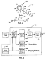
- the printer 10 includes a white light source 12.
- the white light source 12 comprises a xenon arc lamp, however, any suitable white light or other appropriate light source may be utilized.
- a suitable xenon arc lamp may be purchased from the Oriel Company or Optical Radiation Corporation.
- a collimating lens 14 is provided which collimates light emanating from the white light source 12 to form a beam of white light 16.
- the beam of white light 16 is then passed through a modulator 18 for modulating the intensity of the beam of white light 16 in accordance with image data with respect to a predetermined color.
- image data obtained from a digital source such as the Photo CD scanner, sold by the Eastman Kodak Company.
- the modulator 18 may take a variety of different forms.
- modulator 18 may comprise a PLZT or LCD, or any other appropriate light modulator.
- the modulator 18 comprises a PLZT.
- a suitable PLZT that may be used is the Motorola SCS 1108A solid state ceramic shutter.
- a cylindrical lens 20 converts the beam 16 into a spot image, which can be used for writing on photosensitive material.
- the beam 16 is then passed on to a rotating polygon mirror 22 having a plurality of sides/facets 24, 25, 26, 27, 28, 29.
- the sides 24, 25, 26, 27, 28, 29 of the polygon mirror 22 are designed to reflect the light through an F- ⁇ lens 32 which focuses the beam 16' onto a photosensitive media 30.
- the photosensitive media comprises photographic paper.
- the photosensitive material may comprise of any photosensitive media such as photographic film, electrostatic drum, etc.
- the sides of polygon mirror 22 are provided with absorption filters which are coated on sides/facets 24, 25, 26, 27, 28, 29 such that light corresponding to the color that has been modulated will be reflected onto the photosensitive media 30.
- sides 24 and 27 reflect green light
- sides 25 and 28 reflect blue light
- sides 26 and 29 reflect red light.
- the modulator 18 modulates the particular colored beam of light that is being reflected by the side upon which the beam 16 is being directed. For example, as illustrated, the modulator 18 is modulating the green color in the beam of light 16, such that the beam of light 16' being reflected from the polygon mirror 22 will be exposed onto the photosensitive media 30.
- F- ⁇ lens 32 focuses the spot as the beam 16 is deflected across the photosensitive media 30.
- image information red, green, or blue data, which corresponds to the filter laminate on the polygon mirror
- modulator 18 uses modulator 18 to modulate the light beam 16.
- a single red, green, or blue line of information is exposed onto the photographic media 30 as the polygon 22 rotates.
- a full line of color image is made by exposing the red, green, and blue information sequentially onto the photosensitive material 30.
- the photosensitive media 30 is moved by two pairs 35 of pinch rollers which are rotated by stepper motor 34 so that the next line can be written onto the photosensitive material. This process of writing each line of image is repeated until a full color image has been exposed onto the photosensitive media 30.
- Image data which is representative of digital information with respect to a particular image, for example, as obtained from a digital scanner which has scanned a developed film negative, is sent to the printer 10 with the appropriate image data being sent to digital signal processor 42.
- a three-channel 12-bit lookup table (LUT) 44 is used for determining the values that are appropriate for generating the intensity levels of density on the photosensitive material.
- the output of the LUT 44 is converted to an analog signal by converter 46, which is amplified as required by the modulator 18.
- a start of scan pulse synchronizes the rotation of the polygon mirror 22 in face with the data stream being supplied.
- Stepper motor drives 48, 49 provide signals for controlling motor 34 and a second motor (not shown) for rotating the polygon mirror 22 so that photosensitive media will be properly exposed. The process is completed when all the data information has been transferred and written onto photosensitive material.
- An microprocessor 45 is provided for controlling the operation of the printer 10 as is well known in the art.
- a rotating polygon mirror is used for selecting out the modulated color of light and for presenting it onto the photosensitive material.
- a rotating diffraction grating 50 having sections 51, 52, 53, 54, 55, 56, 57, 58, 59.
- Grating 50 may be used in the apparatus of Figure 2 taking the place of rotating polygon mirror. Sections 51, 54, and 57 selects out a first predetermined colored light, for example, green, whereas diffraction grating sections 52, 55 and 58 select out the blue colored light, and sections 53, 56 and 59 select out the red colored light.
- the grating comprises a surface relief or modulated refractive index with transmissive features spaced by the grating pitch d.
- d the desired color
- the desired color may be obtained, e.g., red, green or blue.
- each successive color will be selected out and diffracted through the lens onto the photosensitive material. The remaining part of the system will be identical to that previously described.
- a white light source is provided which is modulated in accordance with the three primary colors (e.g., red, blue, and green).
- the light source may provide any other combination of colored light and any desired color component may be modulated.
Landscapes
- Physics & Mathematics (AREA)
- General Physics & Mathematics (AREA)
- Optics & Photonics (AREA)
- Laser Beam Printer (AREA)
- Facsimile Scanning Arrangements (AREA)
- Fax Reproducing Arrangements (AREA)
- Color, Gradation (AREA)
- Exposure Or Original Feeding In Electrophotography (AREA)
Claims (10)
- Printer (10) zum Belichten eines lichtempfindlichen Materials (30), gekennzeichnet durcheine Lichtquelle (12) zum Erzeugen von Licht, das aus mindestens zwei Farben besteht;einen Kollimator (14) zum Kollimieren des von der Lichtquelle (12) erzeugten Lichts, um einen Lichtstrahl (16) zu bilden;einen Modulator (18) zum Modulieren des Strahls (16) entsprechend den Bilddaten für eine der mindestens zwei Farben;ein Filter (22, 24, 25, 26, 27, 28, 29; 50, 51, 52, 53, 54, 55, 56, 57, 58, 59) zum Ausfiltern eines Lichtstrahls (16'), der eine Farbe aufweist, die moduliert worden ist; undeine Strahllenkvorrichtung (32), die den modulierten, farbigen und gefilterten Strahl (16') auf ein lichtempfindliches Material (30) lenkt.
- Printer nach Anspruch 1, dadurch gekennzeichnet, daß die Lichtquelle (12) eine Weißlichtquelle ist, wobei der Modulator (18) den Weißlichtstrahl entsprechend den Bilddaten für eine vorgegebene Farbe moduliert.
- Printer nach Anspruch 2, dadurch gekennzeichnet, daß eine achromatisierte Zylinderlinse (20) vorgesehen ist, welche den modulierten Weißlichtstrahl (16) fokussiert, bevor er auf das Filter (22) gelenkt wird.
- Printer nach einem der Ansprüche 1 - 3, dadurch gekennzeichnet, daß die Strahllenkvorrichtung (32) eine Linse (32) aufweist, welche den farbigen, gefilterten Strahl (16') auf das lichtempfindliche Material (30) fokussiert.
- Printer nach einem der vorhergehenden Ansprüche, dadurch gekennzeichnet, daß das Filter (22, 24, 25, 26, 27, 28, 29) einen Umlenkspiegel (22) aufweist, dessen Oberfläche mit einem Reflexionsfilter beschichtet ist.
- Printer nach einem der Ansprüche 1 - 4, dadurch gekennzeichnet, daß das Filter (50, 51, 52, 53, 54, 55, 56, 57, 58, 59) ein Beugungsgitter (50) aufweist, dessen Gitterkonstante derart bemessen ist, daß die Schwerpunktwellenlänge im Schwerpunktwellenlängenbereich des Lichtstrahls liegt, der moduliert wird.
- Printer nach einem der Ansprüche 1 - 4, dadurch gekennzeichnet, daß das Filter (22, 24, 25, 26, 27, 28, 29) einen rotierenden Polygonspiegel (22) mit einer Vielzahl von Spiegelflächen (24, 25, 26, 27, 28, 29) aufweist, die mit wechselnden Filtern beschichtet sind, von denen jedes einem der modulierten Lichtstrahlen entspricht, so daß nur der farbige modulierte Lichtstrahl vom Filter reflektiert wird.
- Printer nach einem der vorhergehenden Ansprüche, dadurch gekennzeichnet, daß der Modulator (18) den Strahl (16) entsprechend den drei Grundfarben moduliert.
- Verfahren zum Schreiben eines Bildes auf ein lichtempfindliches Material (30) unter Verwendung eines mehrere Farbkomponenten aufweisenden modulierten Lichtstrahls (16'), wobei das Verfahren folgende Schritte umfaßt:sequentielles Modulieren jeder Farbkomponente des Lichtstrahls (16) einzeln entsprechend den Bilddaten bezüglich zumindest einer Farbkomponente; undwahlweises Ausfiltern jeder der, zumindest einen, modulierten Farbkomponenten, um einen farbigen Strahl (16') zu erzeugen, und sequentielles Belichten eines lichtempfindlichen Materials (30) mit jedem der, zumindest einen, modulierten, gefilterten und farbigen Lichtstrahlen (16'), um ein Bild entsprechend den Bilddaten zu erzeugen.
- Verfahren nach Anspruch 9, dadurch gekennzeichnet, daß der Lichtstrahl aus Weißlicht besteht, wobei der Weißlichtstrahl entsprechend den Bilddaten für mehrere im voraus ausgewählte Farben moduliert und anschließend jeder der modulierten, farbigen Lichtstrahlen (16') wahlweise gefiltert und ein lichtempfindliches Material (30) mit den modulierten, farbigen Lichtstrahlen sequentiell belichtet wird, um vorgegebenen Bilddaten entsprechend ein Bild zu erzeugen.
Applications Claiming Priority (2)
| Application Number | Priority Date | Filing Date | Title |
|---|---|---|---|
| US29244694A | 1994-08-18 | 1994-08-18 | |
| US292446 | 1994-08-18 |
Publications (2)
| Publication Number | Publication Date |
|---|---|
| EP0697287A1 EP0697287A1 (de) | 1996-02-21 |
| EP0697287B1 true EP0697287B1 (de) | 1998-07-08 |
Family
ID=23124706
Family Applications (1)
| Application Number | Title | Priority Date | Filing Date |
|---|---|---|---|
| EP95202224A Expired - Lifetime EP0697287B1 (de) | 1994-08-18 | 1995-08-16 | Verfahren und Gerät zum Schreiben auf ein lichtempfindliches Material mittels eines modulierten Lichtstrahles |
Country Status (4)
| Country | Link |
|---|---|
| US (2) | US5699143A (de) |
| EP (1) | EP0697287B1 (de) |
| JP (1) | JPH0899438A (de) |
| DE (1) | DE69503326T2 (de) |
Families Citing this family (6)
| Publication number | Priority date | Publication date | Assignee | Title |
|---|---|---|---|---|
| US5819664A (en) * | 1996-09-13 | 1998-10-13 | Steckler; Len | Process for creating textured images |
| FR2798491B1 (fr) * | 1999-09-10 | 2001-11-23 | Intermec Scanner Technology Ct | Dispositif optoelectronique d'acquisition d'images de plans-objets, notamment de codes barres |
| NZ505896A (en) * | 2000-07-21 | 2003-05-30 | Ind Res Ltd | Method and apparatus for assessing or predicting characteristics of wood or other materials by varying frequency of acoustic transmitter and sensing a response |
| US6545636B1 (en) * | 2000-09-11 | 2003-04-08 | Sienna Imaging, Inc. | Photographic process printer using a linear digital exposure engine for printing upon cut-sheet paper |
| US6843177B2 (en) * | 2001-09-14 | 2005-01-18 | Fine Arts Group Llc | Methods and materials for producing an image, and articles comprising materials for producing an image |
| KR100619365B1 (ko) * | 2003-11-03 | 2006-09-12 | 삼성전기주식회사 | 회절 다중빔을 이용한 스캐닝 장치 |
Family Cites Families (18)
| Publication number | Priority date | Publication date | Assignee | Title |
|---|---|---|---|---|
| US1717405A (en) * | 1920-03-16 | 1929-06-18 | John H Powrie | Apparatus for printing positive pictures in natural colors |
| US2566264A (en) * | 1946-05-10 | 1951-08-28 | Eastman Kodak Co | Method of making color prints |
| DE2909336A1 (de) * | 1979-03-09 | 1980-09-18 | Agfa Gevaert Ag | Verfahren und vorrichtung zur erkennung von filmsorten |
| US4424589A (en) * | 1980-04-11 | 1984-01-03 | Coulter Systems Corporation | Flat bed scanner system and method |
| JPS6235352A (ja) * | 1985-08-09 | 1987-02-16 | Konishiroku Photo Ind Co Ltd | 像形成方法及びその装置 |
| US5010414A (en) * | 1985-11-27 | 1991-04-23 | Clapp Roy A | Process eliminating the use of a master positive film for making a duplicate negative of a color motion picture |
| DE3629416C2 (de) * | 1986-08-29 | 1994-02-17 | Agfa Gevaert Ag | Verfahren und Vorrichtung zum punkt- und zeilenweisen Kopieren von Farbbildern |
| JPS63174493A (ja) * | 1987-01-14 | 1988-07-18 | Toshiba Corp | 加色式撮影装置 |
| US4971413A (en) * | 1987-05-13 | 1990-11-20 | Nikon Corporation | Laser beam depicting apparatus |
| US4848863A (en) * | 1987-12-21 | 1989-07-18 | Halotek Ltd. | Multi-wavelength scanning system |
| GB8802025D0 (en) * | 1988-01-29 | 1988-02-24 | Minnesota Mining & Mfg | Imaging method & apparatus |
| JP2690960B2 (ja) * | 1988-09-07 | 1997-12-17 | 株式会社日立製作所 | 拡大投影露光方法及びその装置 |
| US4933687A (en) * | 1988-10-03 | 1990-06-12 | Cirrus Technology Inc. | Laser-actuated digital imaging system |
| JPH0786674B2 (ja) * | 1989-06-13 | 1995-09-20 | 富士写真フイルム株式会社 | ハロゲン化銀カラー写真感光材料及びカラー画像形成方法 |
| US5018805A (en) * | 1989-10-16 | 1991-05-28 | Eastman Kodak Company | Laser printer |
| US5323183A (en) * | 1990-11-13 | 1994-06-21 | Canon Kabushiki Kaisha | Image recording apparatus |
| US5162929A (en) * | 1991-07-05 | 1992-11-10 | Eastman Kodak Company | Single-beam, multicolor hologon scanner |
| US5359388A (en) * | 1993-04-02 | 1994-10-25 | General Signal Corporation | Microlithographic projection system |
-
1995
- 1995-02-13 US US08/387,546 patent/US5699143A/en not_active Expired - Fee Related
- 1995-08-16 DE DE69503326T patent/DE69503326T2/de not_active Expired - Fee Related
- 1995-08-16 EP EP95202224A patent/EP0697287B1/de not_active Expired - Lifetime
- 1995-08-17 JP JP7209539A patent/JPH0899438A/ja active Pending
- 1995-12-19 US US08/575,184 patent/US5612172A/en not_active Expired - Fee Related
Also Published As
| Publication number | Publication date |
|---|---|
| EP0697287A1 (de) | 1996-02-21 |
| DE69503326D1 (de) | 1998-08-13 |
| DE69503326T2 (de) | 1999-02-11 |
| US5612172A (en) | 1997-03-18 |
| US5699143A (en) | 1997-12-16 |
| JPH0899438A (ja) | 1996-04-16 |
Similar Documents
| Publication | Publication Date | Title |
|---|---|---|
| EP0202931B1 (de) | Fotografisches Vollfarb-Laserdiodenbildgerät und Verfahren mit kontinuierlicher Tönung | |
| JP2003103838A (ja) | ハイブリッド光源を有する感光性媒体用のプリント装置 | |
| JPH04502375A (ja) | レーザプリンタ | |
| JPH02311814A (ja) | カラー画像記録装置 | |
| EP0697287B1 (de) | Verfahren und Gerät zum Schreiben auf ein lichtempfindliches Material mittels eines modulierten Lichtstrahles | |
| EP0697288B1 (de) | Digitaler Drucker mit zur Entwicklung modulierter Weisslichtquelle | |
| JP3869362B2 (ja) | 記録媒体用の露光システム | |
| US4012776A (en) | Luminescent screen laser scanning technique | |
| US6734889B2 (en) | Color printer comprising a linear grating spatial light modulator | |
| JPH0643551A (ja) | マスター・イメージの写真材料上への再生 | |
| US4739374A (en) | Color image copying system | |
| EP1271229B1 (de) | Photographisches Entwicklungsgerät mit umschaltbaren Laserstrahlen | |
| JP2819690B2 (ja) | 画像形成装置 | |
| JP2503637Y2 (ja) | カラ―走査露光装置 | |
| JP2515877B2 (ja) | 走査型写真焼付機 | |
| JPH04323670A (ja) | 画像記録装置 | |
| JPH0143689Y2 (de) | ||
| JP2794922B2 (ja) | 画像形成装置 | |
| GB1577637A (en) | Luminescent screen laser scanning technique | |
| JPH08267821A (ja) | 画像記録装置 | |
| JP2002311370A (ja) | 走査光学装置およびこれを備えた写真処理装置 | |
| JPH0318842A (ja) | 画像露光装置 | |
| JPH0396936A (ja) | カラー走査露光装置 | |
| JPS60120063A (ja) | プリント装置用ドットサイズ制御装置 | |
| JPS63222857A (ja) | カラ−画像記録装置 |
Legal Events
| Date | Code | Title | Description |
|---|---|---|---|
| PUAI | Public reference made under article 153(3) epc to a published international application that has entered the european phase |
Free format text: ORIGINAL CODE: 0009012 |
|
| AK | Designated contracting states |
Kind code of ref document: A1 Designated state(s): CH DE FR GB IT LI |
|
| 17P | Request for examination filed |
Effective date: 19960725 |
|
| 17Q | First examination report despatched |
Effective date: 19970307 |
|
| GRAG | Despatch of communication of intention to grant |
Free format text: ORIGINAL CODE: EPIDOS AGRA |
|
| GRAG | Despatch of communication of intention to grant |
Free format text: ORIGINAL CODE: EPIDOS AGRA |
|
| GRAH | Despatch of communication of intention to grant a patent |
Free format text: ORIGINAL CODE: EPIDOS IGRA |
|
| GRAH | Despatch of communication of intention to grant a patent |
Free format text: ORIGINAL CODE: EPIDOS IGRA |
|
| GRAA | (expected) grant |
Free format text: ORIGINAL CODE: 0009210 |
|
| ITF | It: translation for a ep patent filed | ||
| AK | Designated contracting states |
Kind code of ref document: B1 Designated state(s): CH DE FR GB IT LI |
|
| REG | Reference to a national code |
Ref country code: CH Ref legal event code: EP |
|
| REF | Corresponds to: |
Ref document number: 69503326 Country of ref document: DE Date of ref document: 19980813 |
|
| REG | Reference to a national code |
Ref country code: CH Ref legal event code: NV Representative=s name: KIRKER & CIE SA |
|
| ET | Fr: translation filed | ||
| PLBE | No opposition filed within time limit |
Free format text: ORIGINAL CODE: 0009261 |
|
| STAA | Information on the status of an ep patent application or granted ep patent |
Free format text: STATUS: NO OPPOSITION FILED WITHIN TIME LIMIT |
|
| 26N | No opposition filed | ||
| REG | Reference to a national code |
Ref country code: GB Ref legal event code: IF02 |
|
| PGFP | Annual fee paid to national office [announced via postgrant information from national office to epo] |
Ref country code: GB Payment date: 20040707 Year of fee payment: 10 |
|
| PGFP | Annual fee paid to national office [announced via postgrant information from national office to epo] |
Ref country code: FR Payment date: 20040804 Year of fee payment: 10 |
|
| PGFP | Annual fee paid to national office [announced via postgrant information from national office to epo] |
Ref country code: DE Payment date: 20040831 Year of fee payment: 10 |
|
| PGFP | Annual fee paid to national office [announced via postgrant information from national office to epo] |
Ref country code: CH Payment date: 20040914 Year of fee payment: 10 |
|
| PG25 | Lapsed in a contracting state [announced via postgrant information from national office to epo] |
Ref country code: IT Free format text: LAPSE BECAUSE OF NON-PAYMENT OF DUE FEES;WARNING: LAPSES OF ITALIAN PATENTS WITH EFFECTIVE DATE BEFORE 2007 MAY HAVE OCCURRED AT ANY TIME BEFORE 2007. THE CORRECT EFFECTIVE DATE MAY BE DIFFERENT FROM THE ONE RECORDED. Effective date: 20050816 Ref country code: GB Free format text: LAPSE BECAUSE OF NON-PAYMENT OF DUE FEES Effective date: 20050816 |
|
| PG25 | Lapsed in a contracting state [announced via postgrant information from national office to epo] |
Ref country code: LI Free format text: LAPSE BECAUSE OF NON-PAYMENT OF DUE FEES Effective date: 20050831 Ref country code: CH Free format text: LAPSE BECAUSE OF NON-PAYMENT OF DUE FEES Effective date: 20050831 |
|
| PG25 | Lapsed in a contracting state [announced via postgrant information from national office to epo] |
Ref country code: DE Free format text: LAPSE BECAUSE OF NON-PAYMENT OF DUE FEES Effective date: 20060301 |
|
| REG | Reference to a national code |
Ref country code: CH Ref legal event code: PL |
|
| GBPC | Gb: european patent ceased through non-payment of renewal fee |
Effective date: 20050816 |
|
| PG25 | Lapsed in a contracting state [announced via postgrant information from national office to epo] |
Ref country code: FR Free format text: LAPSE BECAUSE OF NON-PAYMENT OF DUE FEES Effective date: 20060428 |
|
| REG | Reference to a national code |
Ref country code: FR Ref legal event code: ST Effective date: 20060428 |