EP0697540A2 - Ressort pneumatique, notamment pour les soupapes d'échange gazeux de moteurs à combustion interne - Google Patents
Ressort pneumatique, notamment pour les soupapes d'échange gazeux de moteurs à combustion interne Download PDFInfo
- Publication number
- EP0697540A2 EP0697540A2 EP95111924A EP95111924A EP0697540A2 EP 0697540 A2 EP0697540 A2 EP 0697540A2 EP 95111924 A EP95111924 A EP 95111924A EP 95111924 A EP95111924 A EP 95111924A EP 0697540 A2 EP0697540 A2 EP 0697540A2
- Authority
- EP
- European Patent Office
- Prior art keywords
- piston
- cylinder
- pneumatic spring
- seal
- tube section
- Prior art date
- Legal status (The legal status is an assumption and is not a legal conclusion. Google has not performed a legal analysis and makes no representation as to the accuracy of the status listed.)
- Granted
Links
- 238000002485 combustion reaction Methods 0.000 title claims description 10
- 238000010276 construction Methods 0.000 description 3
- 238000007789 sealing Methods 0.000 description 2
- 238000011990 functional testing Methods 0.000 description 1
- 238000003754 machining Methods 0.000 description 1
- 238000004519 manufacturing process Methods 0.000 description 1
Images


Classifications
-
- F—MECHANICAL ENGINEERING; LIGHTING; HEATING; WEAPONS; BLASTING
- F16—ENGINEERING ELEMENTS AND UNITS; GENERAL MEASURES FOR PRODUCING AND MAINTAINING EFFECTIVE FUNCTIONING OF MACHINES OR INSTALLATIONS; THERMAL INSULATION IN GENERAL
- F16F—SPRINGS; SHOCK-ABSORBERS; MEANS FOR DAMPING VIBRATION
- F16F9/00—Springs, vibration-dampers, shock-absorbers, or similarly-constructed movement-dampers using a fluid or the equivalent as damping medium
- F16F9/32—Details
- F16F9/36—Special sealings, including sealings or guides for piston-rods
- F16F9/362—Combination of sealing and guide arrangements for piston rods
-
- F—MECHANICAL ENGINEERING; LIGHTING; HEATING; WEAPONS; BLASTING
- F01—MACHINES OR ENGINES IN GENERAL; ENGINE PLANTS IN GENERAL; STEAM ENGINES
- F01L—CYCLICALLY OPERATING VALVES FOR MACHINES OR ENGINES
- F01L1/00—Valve-gear or valve arrangements, e.g. lift-valve gear
- F01L1/46—Component parts, details, or accessories, not provided for in preceding subgroups
- F01L1/462—Valve return spring arrangements
- F01L1/465—Pneumatic arrangements
-
- F—MECHANICAL ENGINEERING; LIGHTING; HEATING; WEAPONS; BLASTING
- F16—ENGINEERING ELEMENTS AND UNITS; GENERAL MEASURES FOR PRODUCING AND MAINTAINING EFFECTIVE FUNCTIONING OF MACHINES OR INSTALLATIONS; THERMAL INSULATION IN GENERAL
- F16F—SPRINGS; SHOCK-ABSORBERS; MEANS FOR DAMPING VIBRATION
- F16F9/00—Springs, vibration-dampers, shock-absorbers, or similarly-constructed movement-dampers using a fluid or the equivalent as damping medium
- F16F9/02—Springs, vibration-dampers, shock-absorbers, or similarly-constructed movement-dampers using a fluid or the equivalent as damping medium using gas only or vacuum
- F16F9/0209—Telescopic
-
- F—MECHANICAL ENGINEERING; LIGHTING; HEATING; WEAPONS; BLASTING
- F16—ENGINEERING ELEMENTS AND UNITS; GENERAL MEASURES FOR PRODUCING AND MAINTAINING EFFECTIVE FUNCTIONING OF MACHINES OR INSTALLATIONS; THERMAL INSULATION IN GENERAL
- F16F—SPRINGS; SHOCK-ABSORBERS; MEANS FOR DAMPING VIBRATION
- F16F9/00—Springs, vibration-dampers, shock-absorbers, or similarly-constructed movement-dampers using a fluid or the equivalent as damping medium
- F16F9/02—Springs, vibration-dampers, shock-absorbers, or similarly-constructed movement-dampers using a fluid or the equivalent as damping medium using gas only or vacuum
- F16F9/04—Springs, vibration-dampers, shock-absorbers, or similarly-constructed movement-dampers using a fluid or the equivalent as damping medium using gas only or vacuum in a chamber with a flexible wall
-
- B—PERFORMING OPERATIONS; TRANSPORTING
- B60—VEHICLES IN GENERAL
- B60G—VEHICLE SUSPENSION ARRANGEMENTS
- B60G2202/00—Indexing codes relating to the type of spring, damper or actuator
- B60G2202/10—Type of spring
- B60G2202/15—Fluid spring
- B60G2202/152—Pneumatic spring
-
- F—MECHANICAL ENGINEERING; LIGHTING; HEATING; WEAPONS; BLASTING
- F16—ENGINEERING ELEMENTS AND UNITS; GENERAL MEASURES FOR PRODUCING AND MAINTAINING EFFECTIVE FUNCTIONING OF MACHINES OR INSTALLATIONS; THERMAL INSULATION IN GENERAL
- F16F—SPRINGS; SHOCK-ABSORBERS; MEANS FOR DAMPING VIBRATION
- F16F2232/00—Nature of movement
- F16F2232/02—Rotary
Definitions
- the invention is based on the preamble of claim 1 from FR-A 2 529 616.
- This known pneumatic spring which is formed from a piston / cylinder unit, is used in an internal combustion engine to reset a gas exchange valve into the closed position.
- the valve stem of a globe valve forms the actuating rod which is connected to the piston in a drive-proof manner.
- the valve stem is arranged on the piston in such a way that it passes through the pneumatic spring chamber and is thus tightly connected to the piston on the one hand to seal the chamber and on the other hand passes through a chamber-side end wall of the cylinder with the interposition of a sliding seal.
- the quality of the tightness of the known pneumatic spring is also essentially determined by the sealing points of the actuating rod or the valve stem. Since a reliable test for leaks in the pneumatic spring only makes sense with its relevant components, the test can only be carried out with the lift valve assigned to the respective spring. This means that the known pneumatic spring can only be tested for tightness and thus for its function in the assembled state in the internal combustion engine.
- a pneumatic spring for an internal combustion engine valve train is known from US Pat. No. 1,695,011, in which numerous piston-cylinder units arranged concentrically around the valve stem are provided instead of the known single-chamber design.
- a test for tightness and function that is independent of the place of use of the spring is conceivable, in addition to the high construction costs, the high friction forces are disadvantageous in any case.
- the invention has for its object to improve a pneumatic spring of the generic one-chamber design so that an independent of the location of the spring test for tightness and function is achieved.
- a pneumatic spring is advantageously achieved as a functional unit in a one-chamber design that is sealed off from the environment and can be checked for tightness and function far from the place of use, without using the actuating rod or the valve stem of a globe valve.
- Another advantage of the invention is that the tight connection between the piston and the actuating rod or valve stem is eliminated.
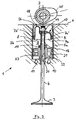
- a pneumatic spring 1 for resetting a lift valve 3 actuated by a control shaft 2 for the gas exchange of an internal combustion engine 4 (not shown in more detail) comprises a pot-like cylinder 5 arranged on the machine side and a pot-like piston 7 connected to the valve stem 6 of the lift valve 3 with the interposition of a Seal 8, the pistons 7 and cylinders 5, which are arranged with their open ends facing one another, delimit a chamber 9 for a compressible gas, which is supplied, for example, via a line 10 and is kept at a predetermined pressure level in a line 11 via a pressure limiting device.
- the latter further comprises an inner boundary which is formed from tube sections 12 and 13, which are arranged on the cylinder 5 and piston 7 and interact in a telescopic manner. These serve to enclose the valve stem 6 of the globe valve 3, which penetrates from a cylinder-side end wall 14 of the cylinder 5 for the drive-proof connection to the piston 7, the pipe sections 12, 13 serving to arrange a seal 15.
- a functional unit of a pneumatic spring 1, which can be checked remotely from the internal combustion engine 4, is thus created, which can be checked for leaks without mounting the valve stem 6 of the lift valve 3.
- the piston-side tube section 12 is arranged to move in and out of the cylinder-side tube section 13, the piston-side tube section 12 being slidably connected over the outer circumference to the seal 15 fixedly arranged on the cylinder-side tube section 13. Furthermore, it can be seen from the drawing that the cup-shaped piston 7 with its piston skirt 7 'according to FIG. 1a circumferentially and according to FIG. 1b over the inner circumference with the seal 8 fixedly arranged on the cylinder 5 cooperates with sliding movement. According to FIG. 1c, the cup-shaped piston has 7 in the free end region of its piston skirt 7 ', the seal 8 is fixedly arranged, which is in sliding connection with the outside of the cylinder 5.
- the cylinder-side tube section 13 is arranged to extend and retract into the piston-side tube section 12, the piston-side tube section 12 being in a slidingly movable connection with the seal 15 fixedly arranged on the cylinder-side tube section 13.
- the piston-like piston 7 with its piston skirt 7 'according to FIG. 2a over the outer circumference and according to FIG. 2b on the inside circumferentially cooperates with the seal 8 fixedly arranged on the cylinder 5.
- FIG. 3 shows a pneumatic spring 1 with pistons 7a and 7b, each with a different design, shown in a half section, the respective piston skirt 7a 'and 7b' of which is connected to the pipe section 16 for reasons of strength via rounded sections 17 and 18, respectively.
- the connecting section 17 serves for a small-volume chamber 9 of the spring 1 with a steep spring characteristic
- the connecting section 18 allows a larger-volume chamber 9 of the spring 1 with otherwise identical construction dimensions for a less steep spring characteristic.
- each piston 7a, 7b is, according to the invention, uncovered in a free end region by the respective piston skirt 7a ', 7b'.
- the piston skirt 7a ', 7b' shortened in this way, which advantageously carries the seal 8 for manufacturing and assembly reasons, the sliding surface of the pipe section 16 which cooperates with the further seal 15 can advantageously be easily and thus inexpensively finished.
- FIG. 3 shows, the wall surrounding the valve stem 6 on the cylinder side and interacting telescopically with the pipe section 16 is, according to the invention, a valve base 21 of the cylinder 5a provided with an opening 20.
- the seal 15 is arranged on the chamber side, so that it is part of the tube section 16 and the valve base 21 is formed with the opening 20 inner boundary of the chamber 9.
- This pneumatic spring 1 can therefore also be checked separately for its function from the place of use in the internal combustion engine.
- a check valve arranged in the path of the feed line 10 in the valve base 21 at 22 and a pressure relief valve provided at 23 are also included in the functional test.
- FIG. 3 also shows that the cylinder 5a is extended beyond the upper stroke position of the piston 7a, 7b, which corresponds to the closed position of the valve 3, for slidably receiving a bucket tappet 24 which, under the action of the cam 25 of the rotating control shaft 2, the stroke valve 3 moved in the opening direction.
- the medium compressed in the chamber 9 drives the lift valve 3 back into the closed position after the maximum stroke has been reached.
- the inventive combination of the pneumatic spring 1 with the bucket tappet 24 to form an assembly unit results in a simple construction of a cylinder head of the internal combustion engine 4, which is not shown in detail.
Landscapes
- Engineering & Computer Science (AREA)
- General Engineering & Computer Science (AREA)
- Mechanical Engineering (AREA)
- Valve Device For Special Equipments (AREA)
Applications Claiming Priority (2)
| Application Number | Priority Date | Filing Date | Title |
|---|---|---|---|
| DE4428677 | 1994-08-12 | ||
| DE4428677 | 1994-08-12 |
Publications (3)
| Publication Number | Publication Date |
|---|---|
| EP0697540A2 true EP0697540A2 (fr) | 1996-02-21 |
| EP0697540A3 EP0697540A3 (fr) | 1996-03-06 |
| EP0697540B1 EP0697540B1 (fr) | 1999-09-29 |
Family
ID=6525592
Family Applications (1)
| Application Number | Title | Priority Date | Filing Date |
|---|---|---|---|
| EP95111924A Expired - Lifetime EP0697540B1 (fr) | 1994-08-12 | 1995-07-28 | Ressort pneumatique, notamment pour les soupapes d'échange gazeux de moteurs à combustion interne |
Country Status (2)
| Country | Link |
|---|---|
| EP (1) | EP0697540B1 (fr) |
| DE (1) | DE59506935D1 (fr) |
Cited By (5)
| Publication number | Priority date | Publication date | Assignee | Title |
|---|---|---|---|---|
| EP0824180A1 (fr) | 1996-08-13 | 1998-02-18 | Bayerische Motoren Werke Aktiengesellschaft, Patentabteilung AJ-3 | Ressort pneumatique pour soupape de moteur |
| WO1998023878A1 (fr) * | 1995-12-07 | 1998-06-04 | Festo Ag & Co. | Unite de suspension, notamment pour vehicules routiers et vehicules sur rails |
| DE10016878A1 (de) * | 2000-04-05 | 2001-10-18 | Bayerische Motoren Werke Ag | Schliessfeder-Vorrichtung für den Ventiltrieb eines Gaswechselventils einer Brennkraftmaschine |
| DE10243388B4 (de) * | 2002-09-13 | 2012-02-09 | Iav Gmbh Ingenieurgesellschaft Auto Und Verkehr | Pneumatische Ventilfeder für Gaswechselventile von Brennkraftmaschinen |
| DE102022108081A1 (de) | 2022-04-05 | 2023-10-05 | Dr. Ing. H.C. F. Porsche Aktiengesellschaft | Pneumatische Ventilfeder |
Families Citing this family (2)
| Publication number | Priority date | Publication date | Assignee | Title |
|---|---|---|---|---|
| EP2208870B1 (fr) | 2009-01-20 | 2013-03-27 | BRP-Powertrain GmbH & Co. KG | Système de ressort pneumatique pour moteur à combustion interne |
| EP2211031B1 (fr) | 2009-01-22 | 2013-07-10 | BRP-Powertrain GmbH & Co. KG | Ressort pneumatique avec couvercle |
Citations (3)
| Publication number | Priority date | Publication date | Assignee | Title |
|---|---|---|---|---|
| US1695011A (en) | 1926-12-31 | 1928-12-11 | Fornaca Guido | Valve gear |
| FR2529616A1 (fr) | 1982-06-30 | 1984-01-06 | Renault Sport | Systeme de rappel pneumatique de soupape pour moteur a combustion interne |
| JPH02283809A (ja) | 1989-04-24 | 1990-11-21 | Honda Motor Co Ltd | 内燃機関の動弁装置 |
Family Cites Families (8)
| Publication number | Priority date | Publication date | Assignee | Title |
|---|---|---|---|---|
| FR3847E (fr) * | 1902-11-20 | 1905-03-14 | Jules Bernard | Dispositif de suspension élastique amortisseur de chocs pour chassis, caisses de véhicules, sièges et sommiers élastiques |
| GB392294A (en) * | 1932-02-09 | 1933-05-18 | Albert Eustace Short | Improvements in or relating to valve mechanism for internal combustion engines |
| FR1227839A (fr) * | 1959-06-22 | 1960-08-24 | Ressort pneumatique pour la suspension des véhicules | |
| GB2122721B (en) * | 1980-06-03 | 1984-08-15 | Lucas Ind Plc | Hydropneumatic suspension units |
| CH671808A5 (en) * | 1983-08-29 | 1989-09-29 | Gualtiero Sartori | Cylinder head for 4-stroke engine - each valve shaft end is removably connected to piston |
| DE3814568A1 (de) * | 1988-04-29 | 1989-11-09 | Stabilus Gmbh | Pneumatisches oder hydropneumatisches aggregat |
| JPH02283811A (ja) * | 1989-04-25 | 1990-11-21 | Honda Motor Co Ltd | 内燃機関の動弁装置 |
| JP2610768B2 (ja) * | 1993-03-31 | 1997-05-14 | 株式会社アマダメトレックス | パンチング金型 |
-
1995
- 1995-07-28 DE DE59506935T patent/DE59506935D1/de not_active Expired - Fee Related
- 1995-07-28 EP EP95111924A patent/EP0697540B1/fr not_active Expired - Lifetime
Patent Citations (3)
| Publication number | Priority date | Publication date | Assignee | Title |
|---|---|---|---|---|
| US1695011A (en) | 1926-12-31 | 1928-12-11 | Fornaca Guido | Valve gear |
| FR2529616A1 (fr) | 1982-06-30 | 1984-01-06 | Renault Sport | Systeme de rappel pneumatique de soupape pour moteur a combustion interne |
| JPH02283809A (ja) | 1989-04-24 | 1990-11-21 | Honda Motor Co Ltd | 内燃機関の動弁装置 |
Cited By (7)
| Publication number | Priority date | Publication date | Assignee | Title |
|---|---|---|---|---|
| WO1998023878A1 (fr) * | 1995-12-07 | 1998-06-04 | Festo Ag & Co. | Unite de suspension, notamment pour vehicules routiers et vehicules sur rails |
| EP0824180A1 (fr) | 1996-08-13 | 1998-02-18 | Bayerische Motoren Werke Aktiengesellschaft, Patentabteilung AJ-3 | Ressort pneumatique pour soupape de moteur |
| DE19632628A1 (de) * | 1996-08-13 | 1998-02-19 | Bayerische Motoren Werke Ag | Pneumatische Feder, insbesondere Schließfeder für ein Gaswechselventil einer Brennkraftmaschine |
| DE10016878A1 (de) * | 2000-04-05 | 2001-10-18 | Bayerische Motoren Werke Ag | Schliessfeder-Vorrichtung für den Ventiltrieb eines Gaswechselventils einer Brennkraftmaschine |
| DE10243388B4 (de) * | 2002-09-13 | 2012-02-09 | Iav Gmbh Ingenieurgesellschaft Auto Und Verkehr | Pneumatische Ventilfeder für Gaswechselventile von Brennkraftmaschinen |
| DE102022108081A1 (de) | 2022-04-05 | 2023-10-05 | Dr. Ing. H.C. F. Porsche Aktiengesellschaft | Pneumatische Ventilfeder |
| DE102022108081B4 (de) | 2022-04-05 | 2023-12-07 | Dr. Ing. H.C. F. Porsche Aktiengesellschaft | Pneumatische Ventilfeder |
Also Published As
| Publication number | Publication date |
|---|---|
| DE59506935D1 (de) | 1999-11-04 |
| EP0697540B1 (fr) | 1999-09-29 |
| EP0697540A3 (fr) | 1996-03-06 |
Similar Documents
| Publication | Publication Date | Title |
|---|---|---|
| DE4206166B4 (de) | Variabler Ventiltrieb für ein Hubventil einer Maschine | |
| DE19844202A1 (de) | Schaltbarer Nockenfolger | |
| DE19908286A1 (de) | Variable Ventilsteuerung für Brennkraftmaschinen | |
| DE4210567B4 (de) | Variabler Ventiltrieb für ein Hubventil einer Maschine | |
| EP0697540A2 (fr) | Ressort pneumatique, notamment pour les soupapes d'échange gazeux de moteurs à combustion interne | |
| EP0623190B1 (fr) | Poussoir a compensation hydraulique du jeu de soupape et piston libre | |
| DE4213147C2 (de) | Variabler Ventiltrieb für ein Hubventil mit zwei durch unterschiedliche Nocken betätigbaren Stößeln | |
| EP0539320B1 (fr) | Dispositif de commande hydraulique d'une soupape d'échappement d'un moteur à combustion interne à piston | |
| DE2814185C3 (de) | Ventilstößel zur wahlweisen Unterbrechung der Betätigung von Gaswechselventilen in Brennkraftmaschinen | |
| EP0193142B1 (fr) | Dispositif de frein moteur pour moteur à combustion interne | |
| DE102004004692A1 (de) | Ventilgesteuerte Expansionsmaschine | |
| DE4128813A1 (de) | Hydraulischer rollenstoessel | |
| DE4202542A1 (de) | Variabler ventiltrieb fuer ein hubventil | |
| DE4202506A1 (de) | Variabler ventiltrieb fuer ein hubventil | |
| DE3902658A1 (de) | Kolbenmkompressor | |
| EP3440321B1 (fr) | Machine à pistons alternatifs | |
| DE2517370A1 (de) | Hydraulische spielausgleichsvorrichtung | |
| DE1958627A1 (de) | Verstellvorrichtung fuer Ventilerhebungen | |
| WO2002014656A1 (fr) | Liaison entre une extremite de queue d"une soupape d"echange de gaz dans un moteur a combustion interne et un element de reglage sous forme de manchon d"un regulateur de soupape | |
| DE4334006C2 (de) | Vorrichtung zur Erhöhung der Motorbremsleistung einer Brennkraftmaschine | |
| DE10358818B3 (de) | Piezoelektrisch-hydraulischer Ventiltrieb und Verfahren zum Betreiben eines piezoelekrisch-hydraulischen Ventiltriebs | |
| DE10207038A1 (de) | Ventiltrieb für eine Brennkraftmaschine | |
| DE10317458B4 (de) | Kältemittelkompressor und Verfahren zum Herstellen eines Kältemittelkompressors | |
| DE4300124C2 (de) | Verfahren und Vorrichtung zur Ventilsteuerung bei Verbrennungsmotoren | |
| DE19632628A1 (de) | Pneumatische Feder, insbesondere Schließfeder für ein Gaswechselventil einer Brennkraftmaschine |
Legal Events
| Date | Code | Title | Description |
|---|---|---|---|
| PUAI | Public reference made under article 153(3) epc to a published international application that has entered the european phase |
Free format text: ORIGINAL CODE: 0009012 |
|
| PUAL | Search report despatched |
Free format text: ORIGINAL CODE: 0009013 |
|
| AK | Designated contracting states |
Kind code of ref document: A2 Designated state(s): DE FR GB IT |
|
| AK | Designated contracting states |
Kind code of ref document: A3 Designated state(s): DE FR GB IT |
|
| 17P | Request for examination filed |
Effective date: 19960829 |
|
| 17Q | First examination report despatched |
Effective date: 19970728 |
|
| GRAG | Despatch of communication of intention to grant |
Free format text: ORIGINAL CODE: EPIDOS AGRA |
|
| GRAG | Despatch of communication of intention to grant |
Free format text: ORIGINAL CODE: EPIDOS AGRA |
|
| GRAH | Despatch of communication of intention to grant a patent |
Free format text: ORIGINAL CODE: EPIDOS IGRA |
|
| GRAH | Despatch of communication of intention to grant a patent |
Free format text: ORIGINAL CODE: EPIDOS IGRA |
|
| GRAA | (expected) grant |
Free format text: ORIGINAL CODE: 0009210 |
|
| AK | Designated contracting states |
Kind code of ref document: B1 Designated state(s): DE FR GB IT |
|
| GBT | Gb: translation of ep patent filed (gb section 77(6)(a)/1977) |
Effective date: 19990929 |
|
| REF | Corresponds to: |
Ref document number: 59506935 Country of ref document: DE Date of ref document: 19991104 |
|
| ET | Fr: translation filed | ||
| ITF | It: translation for a ep patent filed | ||
| PLBE | No opposition filed within time limit |
Free format text: ORIGINAL CODE: 0009261 |
|
| STAA | Information on the status of an ep patent application or granted ep patent |
Free format text: STATUS: NO OPPOSITION FILED WITHIN TIME LIMIT |
|
| 26N | No opposition filed | ||
| REG | Reference to a national code |
Ref country code: GB Ref legal event code: IF02 |
|
| PGFP | Annual fee paid to national office [announced via postgrant information from national office to epo] |
Ref country code: DE Payment date: 20020829 Year of fee payment: 8 |
|
| PGFP | Annual fee paid to national office [announced via postgrant information from national office to epo] |
Ref country code: GB Payment date: 20030724 Year of fee payment: 9 |
|
| PGFP | Annual fee paid to national office [announced via postgrant information from national office to epo] |
Ref country code: FR Payment date: 20030730 Year of fee payment: 9 |
|
| PG25 | Lapsed in a contracting state [announced via postgrant information from national office to epo] |
Ref country code: DE Free format text: LAPSE BECAUSE OF NON-PAYMENT OF DUE FEES Effective date: 20040203 |
|
| PG25 | Lapsed in a contracting state [announced via postgrant information from national office to epo] |
Ref country code: GB Free format text: LAPSE BECAUSE OF NON-PAYMENT OF DUE FEES Effective date: 20040728 |
|
| GBPC | Gb: european patent ceased through non-payment of renewal fee |
Effective date: 20040728 |
|
| PG25 | Lapsed in a contracting state [announced via postgrant information from national office to epo] |
Ref country code: FR Free format text: LAPSE BECAUSE OF NON-PAYMENT OF DUE FEES Effective date: 20050331 |
|
| REG | Reference to a national code |
Ref country code: FR Ref legal event code: ST |
|
| PG25 | Lapsed in a contracting state [announced via postgrant information from national office to epo] |
Ref country code: IT Free format text: LAPSE BECAUSE OF NON-PAYMENT OF DUE FEES Effective date: 20050728 |