EP0698491A2 - Verfahren und Apparat zur Bildaufzeichnung - Google Patents
Verfahren und Apparat zur Bildaufzeichnung Download PDFInfo
- Publication number
- EP0698491A2 EP0698491A2 EP95305708A EP95305708A EP0698491A2 EP 0698491 A2 EP0698491 A2 EP 0698491A2 EP 95305708 A EP95305708 A EP 95305708A EP 95305708 A EP95305708 A EP 95305708A EP 0698491 A2 EP0698491 A2 EP 0698491A2
- Authority
- EP
- European Patent Office
- Prior art keywords
- recording
- image
- recording head
- head
- Prior art date
- Legal status (The legal status is an assumption and is not a legal conclusion. Google has not performed a legal analysis and makes no representation as to the accuracy of the status listed.)
- Granted
Links
Images





Classifications
-
- B—PERFORMING OPERATIONS; TRANSPORTING
- B41—PRINTING; LINING MACHINES; TYPEWRITERS; STAMPS
- B41J—TYPEWRITERS; SELECTIVE PRINTING MECHANISMS, i.e. MECHANISMS PRINTING OTHERWISE THAN FROM A FORME; CORRECTION OF TYPOGRAPHICAL ERRORS
- B41J2/00—Typewriters or selective printing mechanisms characterised by the printing or marking process for which they are designed
- B41J2/005—Typewriters or selective printing mechanisms characterised by the printing or marking process for which they are designed characterised by bringing liquid or particles selectively into contact with a printing material
- B41J2/01—Ink jet
- B41J2/015—Ink jet characterised by the jet generation process
- B41J2/04—Ink jet characterised by the jet generation process generating single droplets or particles on demand
- B41J2/045—Ink jet characterised by the jet generation process generating single droplets or particles on demand by pressure, e.g. electromechanical transducers
- B41J2/04501—Control methods or devices therefor, e.g. driver circuits, control circuits
- B41J2/04551—Control methods or devices therefor, e.g. driver circuits, control circuits using several operating modes
-
- B—PERFORMING OPERATIONS; TRANSPORTING
- B41—PRINTING; LINING MACHINES; TYPEWRITERS; STAMPS
- B41J—TYPEWRITERS; SELECTIVE PRINTING MECHANISMS, i.e. MECHANISMS PRINTING OTHERWISE THAN FROM A FORME; CORRECTION OF TYPOGRAPHICAL ERRORS
- B41J2/00—Typewriters or selective printing mechanisms characterised by the printing or marking process for which they are designed
- B41J2/005—Typewriters or selective printing mechanisms characterised by the printing or marking process for which they are designed characterised by bringing liquid or particles selectively into contact with a printing material
- B41J2/01—Ink jet
- B41J2/015—Ink jet characterised by the jet generation process
- B41J2/04—Ink jet characterised by the jet generation process generating single droplets or particles on demand
- B41J2/045—Ink jet characterised by the jet generation process generating single droplets or particles on demand by pressure, e.g. electromechanical transducers
- B41J2/04501—Control methods or devices therefor, e.g. driver circuits, control circuits
- B41J2/0458—Control methods or devices therefor, e.g. driver circuits, control circuits controlling heads based on heating elements forming bubbles
-
- G—PHYSICS
- G06—COMPUTING OR CALCULATING; COUNTING
- G06K—GRAPHICAL DATA READING; PRESENTATION OF DATA; RECORD CARRIERS; HANDLING RECORD CARRIERS
- G06K15/00—Arrangements for producing a permanent visual presentation of the output data, e.g. computer output printers
- G06K15/02—Arrangements for producing a permanent visual presentation of the output data, e.g. computer output printers using printers
- G06K15/10—Arrangements for producing a permanent visual presentation of the output data, e.g. computer output printers using printers by matrix printers
- G06K15/102—Arrangements for producing a permanent visual presentation of the output data, e.g. computer output printers using printers by matrix printers using ink jet print heads
- G06K15/105—Multipass or interlaced printing
- G06K15/107—Mask selection
Definitions
- the present invention relates to an image recording method and apparatus and, more particularly, to an image recording method and apparatus which can perform a low-power, high-speed print operation using a recording head having a plurality of recording elements.
- Such an apparatus has a plurality of recording element arrays. These recording element arrays are arranged parallel to the convey direction of a recording sheet. A print operation for one recording sheet is completed by the fact that the recording element arrays sequentially scan in a direction perpendicular to the convey direction.
- the number of recording elements included in the above recording element arrays (the length of the recording head) has greatly increased.
- the demand for the above power supply to have higher power is based on an increase in power required for a recording operation with the elongation of a recording head. More specifically, as the number of recording elements increases, the number of recording elements to be driven per unit time increases.
- a required power Pn (I•V•n)•(T•f)•Z where I is the peak value of a rectangular pulse current flowing in each recording element, and V is the power supply voltage value.
- the power Pn increases.
- the value of each parameter In order to realize a high-speed print operation by increasing the number of nozzles with lower power, the value of each parameter must be decreased.
- the parameter Z is a value unique to an image, and a decrease in the value of the parameter f leads to a decrease in print speed. Therefore, it is not preferable that the values of these parameter be decreased.
- an object of the present invention is to obtain an image recording method and apparatus which can achieve a decrease in the power of a power supply and an increase in print speed in using a recording head having a plurality of recording elements.
- An image recording apparatus for recording an image by sequentially scanning a recording head having a plurality of recording elements in a direction different from a convey direction of a recording sheet, comprising: count means for counting data to be actually printed in print data corresponding to each divided area obtained by dividing an area, in which data is printed by scanning said recording head, in a predetermined unit; and selection means for selecting a recording mode corresponding to the predetermined recording area from a plurality of recording modes on the basis of a print duty according to a count value, in each divided area, which is obtained by said count means.
- An image recording method of recording an image by sequentially scanning a recording head having a plurality of recording elements in a direction different from a convey direction of a recording sheet comprising: a count step of counting data to be actually printed in print data corresponding to each divided area obtained by dividing a predetermined recording area in a predetermined unit; and a selection step of selecting a recording mode corresponding to the predetermined recording area on the basis of a print duty according to the count value, in each divided area, which is obtained in the count step.
- the recording apparatus of this embodiment has a plurality of print modes for recording in a predetermined recording area corresponding to the effective recording width of the recording head by a single scanning operation or a plurality of scanning operations.
- Effective pixels in a plurality of print buffers corresponding to areas obtained by dividing the effective recording width of the recording head, which are counted before a print operation, and an effective pixel ratio (print duty) of the number of the effective pixels to the total number of pixels in each buffer is obtained.
- One of the print modes is then selected on the basis of the effective pixel ratio or a corresponding value or code which has the same meaning as the ratio.
- a plurality of print buffers corresponding to areas obtained by dividing the effective recording width of the recording head are prepared, and each print buffer is divided into a plurality of blocks in the scanning direction of the recording head.
- One of the print modes is then selected on the basis of the result obtained by performing a predetermined arithmetic or logic operation with respect to the effective pixel ratios (or corresponding values or codes) in the respective blocks in the plurality of buffers whose contents can be simultaneously recorded.
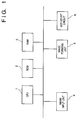
- Fig. 1 shows the schematic arrangement of an image recording apparatus of this embodiment.
- Reference numeral 1 denotes a CPU for controlling the overall image recording apparatus; and 2, a ROM storing an image recording processing program and the like which are executed by the CPU 1. Programs corresponding to the respective processing flow charts to be described later are stored in the ROM 2.
- Reference numeral 3 denotes a RAM used as a working area for executing the above programs or as print buffers; 4, an image input unit capable of inputting an image from an external computer or reading an image through a built-in scanner (not shown); and 5, an image forming unit for receiving image data from a print buffer area in the RAM 3 to form an image.
- a dot count circuit 6 counts effective dots which result in power sumption.
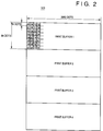
- Fig. 2 shows the arrangement of print buffers in the recording apparatus of the embodiment.
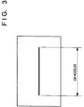
- the recording apparatus of the embodiment uses a 360-dpi (dot per inch) ink-jet recording head shown in Fig. 3 having 128 nozzles.
- the recording head is of the type designed to change the state of an ink by using thermal energy so as to discharge an ink droplet from each nozzle.
- data is transferred from a host computer in units of data corresponding to one line of a text. For this reason, as shown in Fig. 2, the print buffer arrangement is based on a band arrangement having a width of 64 dots.
- a maximum of 80 typical characters each having a width of 36 dots and a height of 60 dots are stored in the print buffer in correspondence with a A4 recording sheet. That is, the effective dot count in the lateral direction is 2,880 (36 x 80) (see Fig. 2).
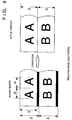
- each area indicated by the gray portion (see the left part of Fig. 4), i.e., each 4-dot area, in the print buffer must be omitted, as indicated by the right part of Fig. 4. Conversion from the left part into the right part of Fig. 4 is performed by dedicated hardware or software. Since this technique is not directly associated with this embodiment of the present invention, detailed description thereof will be omitted.
- each print buffer has a width of 64 dots, and the 64 dots are divided into 8-dot areas. That is, eight dots correspond to 1-byte data.
- Each number in Fig. 2 indicates the lower eight bits of a byte address, and the address increases toward the right end of each buffer.
- Print buffer 1 includes 23,040 bytes (8 x 2,880 bytes). This applies to printer buffer 2, printer buffer 3, and printer buffer 4.
- each buffer corresponds to areas obtained by dividing the effective recording width of the recording head into two equal parts.
- the recording apparatus of this embodiment uses the recording head shown in Fig. 3, which has 128 nozzles.
- This head is driven with a power supply voltage of 24 V, a pulse current of 200 mA, a frequency of 6.25 kHz, and a drive pulse width of 5 ⁇ sec.
- the power consumption of the head is about 23 W according to equation (1).
- an efficiency ⁇ of a DC-DC converter, a switching regulator, or the like for generating a head voltage with high precision is 80%, the power actually consumed is about 29 W in terms of an input from the power supply.
- a power supply (generally 5 V) for the logic, a power supply (which may be commonly used as a head drive power supply) for a motor for feeding a paper sheet and a motor for driving the recording head carriage, and the like are required. That is, a total power of 35 to 40 W is required for the power supply. If such power is to be provided through a power supply such as an inexpensive power adaptor, the power adaptor will increase in size and weight, and hence is not suitable for practical use.
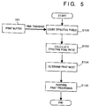
- step S102 before the contents of print buffers (101 in Figs. 2 and 5) are printed, the print dots, i.e., the black dots to be recorded, in a print buffer 101 are counted.
- This operation is performed by transferring the data in the print buffer 101 to a dot count circuit 6 according to for example the DMA transfer scheme.
- the DMA transfer is controlled by a DMA control unit embodied in CPU 1.
- step S103 the average density, i.e., the effective pixel ratio, of an image to be recorded from the print buffer is obtained from the count value.
- step S104 a print mode (recording mode) is determined on the basis of the effective pixel ratio obtained in this manner.
- the effective pixel ratio of both print buffers 1 and 2 is lower than a predetermined value, it is determined that the print duty is low, and the contents of print buffers 1 and 2 are simultaneously printed. If, however, the effective pixel ratio of one of print buffers 1 and 2 is higher than the predetermined value, it is determined that the print duties are high, the contents of the respective print buffers are non-simultaneously printed.
- the contents of print buffer 1 are recorded by the first scanning operation
- the contents of print buffer 2 are recorded by the second scanning operation.
- the contents of print buffers 1 and 2 may be recorded by two scanning operations in a staggered form.
- dots corresponding to the locations indicated in black are recorded by the first scanning operation, and dots corresponding to the locations indicated in white are recorded by the second scanning operation.
- Printer buffers 3 and 4 are controlled in the same manner.
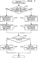
- Fig. 7 shows a detailed flow chart associated with step S104 in Fig. 5, which will be described later.
- step S105 an image is formed in accordance with the print mode (recording mode) set in step S104.
- step S104 of Fig. 5 will be described in detail below with reference to Fig. 7.
- step S1000 it is checked whether the locations of image data to be printed next are print buffers 1 and 2 or print buffers 3 and 4. If the locations are print buffers 1 and 2, the flow advances to step S1200. If the locations are print buffers 3 and 4, the flow advances to step S1100.
- step S1100 the print dots of the image data stored in print buffer 3 are counted, and a print ratio S3 is calculated.
- step S1101 the effective dots of the image data stored in print buffer 4 are counted, and a print ratio S4 is calculated.
- step S1200 the effective dots of the image data stored in print buffer 1 are counted, and a print ratio S1 is calculated.
- step S1101 the effective dots of the image data stored in print buffer 2 are counted, and a print ratio S2 is calculated.
- step S1300 if control is transferred from step S1201, the print ratios S1 and S2 are compared with a predetermined threshold. If the ratios are lower than the predetermined threshold, the flow advances to step S1302 to perform a 1-pass print operation using the 128 nozzles. If control is transferred from step S1101, the print ratios S3 and S4 are compared with a predetermined threshold. If the ratios are greater than the predetermined threshold, the flow advances to step S1301 to perform a 2-pass print operation using the 64 nozzles.
- a recording operation is performed by using a half portion of the elongated recording head, i.e., the 64 nozzles, in correspondence with one scanning operation. For this reason, the average power consumption of the recording head is reduced to a half.
- the effective pixel ratio is determined before the contents of a print buffer are recorded. For this reason, even if a recording operation for one paper sheet includes a low-density text print operation and a high-density graphic print operation, the use of the 128 nozzles and the use of the 64 nozzles can be flexibly selected in accordance with the respective print operations.
- Fig. 8 shows the second embodiment of the present invention.
- one print buffer shown in Fig. 2 is divided into a plurality of blocks in the scanning direction of the recording head.
- Fig. 8 shows the concept of a print operation on a recording medium.
- an effective print area having a width of 2,880 dots is assigned to a recording medium in the direction of abscissa.
- This effective print area is divided into 16 areas, and block numbers 1 to 16 are assigned to the respective effective print areas.
- One effective print area is defined as a 180-dot area.
- Four drawing areas 1 to 4 are set in the direction of abscissa of the recording medium.
- Print buffers 1 to 4 in Fig. 1 correspond to the respective drawing areas.
- a plurality of types of print operations are indicated in the respective blocks in drawing areas 1 and 2.
- a symbol "%" indicates the effective pixel ratio of each block, i.e., the ratio of the number of dots to be actually recorded to the total number of dots included in each block described above.
- the block number 2 in drawing area 2 is indicated as a block which is entirely subjected to a solid black print operation.
- the effective pixel ratio of this block is 100%.
- Each of the block number 6 in drawing areas 1 and 2 is indicated as a block having an effective pixel ratio of 50% and subjected to a halftone print operation.
- each block number 11 in drawing areas 1 and 2 is indicated as a block in which the ratio of a solid black print area to the total area of the block is 35% or less.
- Fig. 9 shows a density flag register storing results obtained by normalizing the effective pixel ratio in the 16 blocks in each drawing area in Fig. 8 with digital values of 0 and 1. For example, normalization is performed such that an effective pixel ratio of 35% or more is set to be "1"; and an effective pixel ratio of less than 35%, "0".
- bit 15 of this density flag register corresponds to block 1
- bit 0 corresponds to block 16.
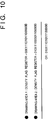
- Fig. 10 shows the contents of the density flag register which correspond to drawing areas 1 and 2. For example, since each of the blocks of block numbers 1 to 3 in drawing area 1 has an effective pixel ratio of 0%, bit 15 to bit 13 are "0". Since each of blocks 4 and 5 is indicated as a block having an effective pixel ratio of 35% or more, bits 12 and 11 are "1". Similarly, the contents of the density flag register are correlated to the respective bits up to bit 0.
- Fig. 10 shows the calculation result.
- the OR result corresponding to the case shown in Fig. 8 indicates that all the bits are not "0". This means that a block having an effective pixel ratio of 35% is present in one of drawing areas 1 and 2. That is, it is determined that the print duty is high.
- drawing areas 1 and 2 are printed by two scanning operations. That is, as described in the first embodiment, a print operation corresponding to drawing area 1 is executed by the first scanning operation, and a print operation corresponding to drawing area 2 is executed by the second scanning operation.
- the dots corresponding to the black portions of the staggered pattern shown in Fig. 3 are printed by the first scanning operation, and the dots corresponding to the white portions are printed by the second scanning operation.
- Drawing areas 3 and 4 are processed in the same manner as in the case of drawing areas 1 and 2.
- Fig. 11 is a flow chart showing the above processing.
- step 104 in Fig. 5 The detailed processing procedure in step 104 in Fig. 5 will be described next with reference to Fig. 11.
- step S8000 it is checked whether image data to be printed next are stored in print buffers 1 and 2 or print buffers 3 and 4. If the data are stored in print buffers 1 and 2, the flow advances to step S8200. If the data are stored in print buffers 3 and 4, the flow advances to step S8100.
- step S8100 dots in each block in print buffer 3 are counted, and a density flag is calculated and set.
- step S8101 dots in each block in print buffer 4 are counted, and a density flag is calculated and set.
- step S8200 dots in each block in print buffer 1 are counted, and a density flag is calculated and set.
- step S8201 dots in each block in print buffer 2 are counted, and a density flag is calculated and set.
- step S8300 it is checked whether the OR in the density flag register is "0". If the OR is "0", the flow advances to step S8302 to perform a i-pass print operation using the 128 nozzles. If the OR is not "0", the flow advances to step S8301 to perform a 1-pass print operation using the 64 nozzles.
- determination of the power consumption in a local area in each drawing area can be performed, and the peak power consumption of the power supply can be decreased by selecting optimal nozzles and an optimal print processing method. Since the target peak supply power can be decreased in designing a power supply, a reduction in the size and cost of the power supply can be realized.
- the recording head has 128 nozzles, and a maximum of two print buffers whose contents can be simultaneously recorded.
- the embodiments of the present invention can also be applied to a longer recording head having, e.g., 256 nozzles, 512 nozzles, or 1,024 nozzles.
- the number of print buffers whose contents can be simultaneously recorded is increased to 4, 8, or 16. If, for example, a predetermined number or more of blocks exhibit effective pixel ratios exceeding a predetermined value, it suffices to print the contents of the corresponding print buffers are printed by a plurality of scanning operations.
- one print buffer has a height of 64 dots. It is, however, apparent that the present invention is not limited to this. In each embodiment described above, since each print buffer is divided in the direction of the effective recording width of the recording head, recording can be separately performed by a plurality of scanning operations. However, the present invention can be applied to a case wherein each print head is divided only in the scanning direction.
- the embodiments applied to the ink-jet printer have been mainly described above. As is apparent, however, the present invention is not limited to the ink-jet printer, and can be applied to a thermal printer as well.
- Fig. 12 is an external view of an ink-jet recording apparatus IJRA to which the present invention can be applied.
- a lead screw 5005 is rotated via driving-force transmission gears 5011 and 5009 in cooperation with the forward-reverse rotation of a driving motor 5013.
- a carriage HC which is engaged with a spiral groove 5004 of the lead screw 5005, has a pin (not shown), and is reciprocally moved in the directions of arrows a and b.
- An ink-jet cartridge IJC is mounted on the carriage HC.
- Reference numeral 5002 denotes a sheet pressing plate, which presses a paper sheet against a platen 5000 across the moving direction of the carriage.
- Reference numerals 5007 and 5008 denote photocouplers, which constitute a home position detection means for confirming the presence of a lever 5006 of the carriage in the corresponding region, and, e.g., switching the rotational direction of the motor 5013.
- Reference numeral 5016 denotes a member for supporting a cap member 5022 for capping the front surface of the recording head; and 5015, a suction means for drawing the interior of the cap by suction.
- the suction means 5015 performs suction recovery of the recording head via an intra-cap opening 5023.
- Reference numeral 5017 denotes a cleaning blade; and 5019, a member for movably supporting the blade in the back-and-forth direction. These members are supported on a main body support plate 5018.
- Reference numeral 5012 denotes a lever for initiating the suction operation of the suction recovery operation.
- the lever 5012 moves upon movement of a cam 5020 engaged with the carriage, and its movement control is realized by a known transmission means such as clutch switching of the driving force from the driving motor.
- capping, cleaning, and suction recovery operations are executed at their corresponding positions upon operation of the lead screw 5005 when the carriage reaches a region at the side of the home position.
- the present invention is not limited to this as long as these operations are executed at known timings.
- reference numeral 1700 denotes an interface for inputting a recording signal; 1701, an MPU; 1702, a program ROM for storing control programs executed by the MPU 1701; and 1703, a dynamic RAM for storing various data (the recording signal, recording data to be supplied to the head, and the like).
- Reference numeral 1704 denotes a gate array for executing supply control of recording data to a recording head 1708, and also executing data transfer control among the interface 1700, the MPU 1701, and the DRAM 1703.
- Reference numeral 1710 denotes a carrier motor for feeding the recording head 1708; and 1709, a feed motor for feeding a recording paper sheet.
- Reference numeral 1705 denotes a head driver for driving the head; and 1706 and 1707, motor drivers for respectively driving the feed motor 1709 and the carrier motor 1710.
- Note that reference numeral 1720 denote a printer controller.
- the operation of the above-mentioned control arrangement will be described below.
- the recording signal is converted into recording data for printing between the gate array 1704 and the MPU 1701.
- the motor drivers 1706 and 1707 are driven, and the recording head is driven in accordance with the recording data supplied to the head driver 1705, thus executing the printing operation.
- the present invention may be applied to a system constituted by a plurality of apparatuses and to an apparatus constituted by a single device.
- the present invention can be applied to a case wherein the above object can be achieved by supplying programs to a system or an apparatus.
- the effective pixel ratios of a plurality of print buffers corresponding to drawing areas to be subjected to the next recording operation are checked, and print modes are variably controlled on the basis of the check result, thereby providing a recording method and apparatus which can use a low-power, low-cost power supply.
- an image having a low effective pixel ratio e.g., a text, which exhibits a high frequency of occurrence
- a graphic or pictorial image having a high effective pixel ratio is printed by a plurality of scanning operations. That is, there are provided a recording method and apparatus which can flexibly perform recording processing in accordance with the characteristics of an image to be printed.
- print data can be printed at a high speed without using a large-capacity power supply.
Landscapes
- Physics & Mathematics (AREA)
- Engineering & Computer Science (AREA)
- Mathematical Physics (AREA)
- General Engineering & Computer Science (AREA)
- General Physics & Mathematics (AREA)
- Theoretical Computer Science (AREA)
- Ink Jet (AREA)
- Electronic Switches (AREA)
Applications Claiming Priority (3)
| Application Number | Priority Date | Filing Date | Title |
|---|---|---|---|
| JP199827/94 | 1994-08-24 | ||
| JP19982794 | 1994-08-24 | ||
| JP19982794A JP3376118B2 (ja) | 1994-08-24 | 1994-08-24 | 画像記録方法とその装置 |
Publications (3)
| Publication Number | Publication Date |
|---|---|
| EP0698491A2 true EP0698491A2 (de) | 1996-02-28 |
| EP0698491A3 EP0698491A3 (de) | 1996-06-26 |
| EP0698491B1 EP0698491B1 (de) | 2003-08-13 |
Family
ID=16414307
Family Applications (1)
| Application Number | Title | Priority Date | Filing Date |
|---|---|---|---|
| EP95305708A Expired - Lifetime EP0698491B1 (de) | 1994-08-24 | 1995-08-16 | Verfahren und Apparat zur Bildaufzeichnung |
Country Status (4)
| Country | Link |
|---|---|
| US (1) | US6155663A (de) |
| EP (1) | EP0698491B1 (de) |
| JP (1) | JP3376118B2 (de) |
| DE (1) | DE69531474T2 (de) |
Cited By (1)
| Publication number | Priority date | Publication date | Assignee | Title |
|---|---|---|---|---|
| EP0798663A3 (de) * | 1996-03-27 | 1998-08-05 | Canon Kabushiki Kaisha | Punktdrucker und Druckverfahren |
Families Citing this family (5)
| Publication number | Priority date | Publication date | Assignee | Title |
|---|---|---|---|---|
| EP1112853B1 (de) * | 1999-12-28 | 2009-02-25 | Canon Kabushiki Kaisha | Tintenstrahlaufzeichnungsverfahren und Tintenstrahlaufzeichnungsgerät mit bi-direktionaler Aufzeichnung |
| US7347519B2 (en) | 2004-05-26 | 2008-03-25 | Canon Kabushiki Kaisha | Printing apparatus, controlling method and computer program |
| JP2012020526A (ja) * | 2010-07-15 | 2012-02-02 | Canon Inc | インクジェット記録装置および記録方法 |
| JP6023492B2 (ja) | 2011-08-01 | 2016-11-09 | キヤノン株式会社 | 記録装置及び記録方法 |
| JP7135751B2 (ja) * | 2018-11-13 | 2022-09-13 | 株式会社リコー | 液体循環装置、液体を吐出する装置 |
Citations (1)
| Publication number | Priority date | Publication date | Assignee | Title |
|---|---|---|---|---|
| US12034693B2 (en) | 2013-12-31 | 2024-07-09 | Google Llc | Systems and methods for displaying unseen labels in a clustering in-box environment |
Family Cites Families (24)
| Publication number | Priority date | Publication date | Assignee | Title |
|---|---|---|---|---|
| JPS55119784A (en) * | 1979-03-07 | 1980-09-13 | Seikosha Co Ltd | Recording unit |
| JPS58138658A (ja) * | 1982-02-10 | 1983-08-17 | Sharp Corp | インクジエツトプリンタの印字制御装置 |
| JPS6072756A (ja) * | 1983-09-30 | 1985-04-24 | Ishida Scales Mfg Co Ltd | 発熱ヘツドの制御回路 |
| JPH0647290B2 (ja) * | 1984-09-25 | 1994-06-22 | ブラザー工業株式会社 | 印字装置 |
| US4653940A (en) * | 1984-09-25 | 1987-03-31 | Brother Kogyo Kabushiki Kaisha | Dot-matrix printer with dot counter for efficient high-quality printing |
| DE3612469C2 (de) * | 1985-04-15 | 1999-02-18 | Canon Kk | Tintenstrahl-Aufzeichnungsgerät |
| JPS6342874A (ja) * | 1986-08-08 | 1988-02-24 | Fujitsu Ltd | プリンタ |
| US4763137A (en) * | 1986-10-01 | 1988-08-09 | International Business Machines Corporation | Two pass thermal printing |
| EP0318328B1 (de) * | 1987-11-27 | 1993-10-27 | Canon Kabushiki Kaisha | Tintenstrahlaufzeichnungsgerät |
| JPH01305396A (ja) * | 1988-06-03 | 1989-12-08 | Mitsubishi Electric Corp | 番組予約装置 |
| US4967203A (en) * | 1989-09-29 | 1990-10-30 | Hewlett-Packard Company | Interlace printing process |
| JPH03164266A (ja) * | 1989-11-24 | 1991-07-16 | Fujitsu Ltd | プリンタ制御方法 |
| JP2508356B2 (ja) * | 1990-04-24 | 1996-06-19 | 株式会社精工舎 | 印字制御方法 |
| JP3068637B2 (ja) * | 1990-09-10 | 2000-07-24 | キヤノン株式会社 | シリアル記録装置 |
| DE69126590T2 (de) * | 1990-09-28 | 1997-10-02 | Fujitsu Ltd | Zeilenwärmedrucker |
| JP3074575B2 (ja) * | 1990-09-28 | 2000-08-07 | 富士通株式会社 | サーマルプリンタ |
| JP3084452B2 (ja) * | 1991-03-08 | 2000-09-04 | セイコーインスツルメンツ株式会社 | ラインサーマルプリンター |
| JPH04338563A (ja) * | 1991-05-15 | 1992-11-25 | Minolta Camera Co Ltd | 画像記録装置 |
| JPH04353466A (ja) * | 1991-05-31 | 1992-12-08 | Canon Inc | インクジェット記録方法及び装置 |
| JP2986124B2 (ja) * | 1991-06-14 | 1999-12-06 | キヤノン株式会社 | インクジェット記録装置 |
| CA2074875C (en) * | 1991-08-02 | 2000-02-15 | Miyuki Matsubara | Ink jet recording method |
| JPH05229162A (ja) * | 1992-02-24 | 1993-09-07 | Rohm Co Ltd | サーマルヘッド及びそれを備えた電子機器 |
| JPH06143648A (ja) * | 1992-10-30 | 1994-05-24 | Casio Comput Co Ltd | サーマルプリンタ装置 |
| JP3397350B2 (ja) * | 1992-12-17 | 2003-04-14 | キヤノン株式会社 | 記録装置 |
-
1994
- 1994-08-24 JP JP19982794A patent/JP3376118B2/ja not_active Expired - Lifetime
-
1995
- 1995-08-15 US US08/515,214 patent/US6155663A/en not_active Expired - Lifetime
- 1995-08-16 DE DE69531474T patent/DE69531474T2/de not_active Expired - Lifetime
- 1995-08-16 EP EP95305708A patent/EP0698491B1/de not_active Expired - Lifetime
Patent Citations (1)
| Publication number | Priority date | Publication date | Assignee | Title |
|---|---|---|---|---|
| US12034693B2 (en) | 2013-12-31 | 2024-07-09 | Google Llc | Systems and methods for displaying unseen labels in a clustering in-box environment |
Cited By (2)
| Publication number | Priority date | Publication date | Assignee | Title |
|---|---|---|---|---|
| EP0798663A3 (de) * | 1996-03-27 | 1998-08-05 | Canon Kabushiki Kaisha | Punktdrucker und Druckverfahren |
| US6085028A (en) * | 1996-03-27 | 2000-07-04 | Canon Kabushiki Kaisha | Recording apparatus and method for recording an image with drive data calculated in accordance with image data and context data |
Also Published As
| Publication number | Publication date |
|---|---|
| EP0698491B1 (de) | 2003-08-13 |
| JP3376118B2 (ja) | 2003-02-10 |
| DE69531474T2 (de) | 2004-07-08 |
| DE69531474D1 (de) | 2003-09-18 |
| JPH0858080A (ja) | 1996-03-05 |
| EP0698491A3 (de) | 1996-06-26 |
| US6155663A (en) | 2000-12-05 |
Similar Documents
| Publication | Publication Date | Title |
|---|---|---|
| EP1953681B1 (de) | Druckkopf, Druckkopfsteuerungsverfahren, und Datenausgabegerät | |
| US5949445A (en) | Printing apparatus and method | |
| US7347519B2 (en) | Printing apparatus, controlling method and computer program | |
| US7207644B2 (en) | Printing apparatus and printing control method for controlling the number of printing elements used in printing | |
| US6155663A (en) | Image recording method and apparatus | |
| EP0950945B1 (de) | Bilderzeugungsgerät und System, Datenverarbeitungsgerät und deren Steuerungsverfahren | |
| EP1355263B1 (de) | Druckgerät und Pufferverwaltungsverfahren | |
| US20050129443A1 (en) | Printing apparatus, data processing method for printing apparatus, and printing system | |
| JP3179674B2 (ja) | 画像記録方法とその装置 | |
| US6147766A (en) | Printing apparatus for increasing efficiency in transmitting image data between internal control units | |
| JP4048677B2 (ja) | 印刷時の条件に応じて使用ノズル数を変更する印刷 | |
| JP2006289859A (ja) | 記録装置、及び記録制御方法 | |
| US7535593B2 (en) | Printing apparatus, data processing method for printing apparatus, and printing system | |
| US20080049237A1 (en) | Image processing apparatus, image printing apparatus and printing data generation method | |
| JP2000025279A (ja) | バンドスキャン型ラスタプロッタ | |
| US20020126163A1 (en) | Image printing apparatus and method | |
| JP2009101667A (ja) | 記録装置及び記録装置の制御方法 | |
| US6328396B1 (en) | Combining multiple printmodes into a single carriage sweep | |
| JPH08174909A (ja) | 印刷制御装置及び方法 | |
| JPH08323983A (ja) | 記録装置及び方法 | |
| JPH09226185A (ja) | 記録方法及びその記録装置 | |
| JPH09226175A (ja) | 画像処理装置及び方法 | |
| JP2000246963A (ja) | 記録装置および記録方法 | |
| JP2000255046A (ja) | 記録装置 | |
| JP2001253064A (ja) | 印刷媒体の端部において使用ノズル数を変更する印刷 |
Legal Events
| Date | Code | Title | Description |
|---|---|---|---|
| PUAI | Public reference made under article 153(3) epc to a published international application that has entered the european phase |
Free format text: ORIGINAL CODE: 0009012 |
|
| AK | Designated contracting states |
Kind code of ref document: A2 Designated state(s): DE FR GB IT |
|
| PUAL | Search report despatched |
Free format text: ORIGINAL CODE: 0009013 |
|
| AK | Designated contracting states |
Kind code of ref document: A3 Designated state(s): DE FR GB IT |
|
| 17P | Request for examination filed |
Effective date: 19961106 |
|
| 17Q | First examination report despatched |
Effective date: 19970506 |
|
| GRAH | Despatch of communication of intention to grant a patent |
Free format text: ORIGINAL CODE: EPIDOS IGRA |
|
| GRAH | Despatch of communication of intention to grant a patent |
Free format text: ORIGINAL CODE: EPIDOS IGRA |
|
| GRAA | (expected) grant |
Free format text: ORIGINAL CODE: 0009210 |
|
| AK | Designated contracting states |
Designated state(s): DE FR GB IT |
|
| REG | Reference to a national code |
Ref country code: GB Ref legal event code: FG4D |
|
| REF | Corresponds to: |
Ref document number: 69531474 Country of ref document: DE Date of ref document: 20030918 Kind code of ref document: P |
|
| ET | Fr: translation filed | ||
| PLBE | No opposition filed within time limit |
Free format text: ORIGINAL CODE: 0009261 |
|
| STAA | Information on the status of an ep patent application or granted ep patent |
Free format text: STATUS: NO OPPOSITION FILED WITHIN TIME LIMIT |
|
| 26N | No opposition filed |
Effective date: 20040514 |
|
| PGFP | Annual fee paid to national office [announced via postgrant information from national office to epo] |
Ref country code: DE Payment date: 20140831 Year of fee payment: 20 |
|
| PGFP | Annual fee paid to national office [announced via postgrant information from national office to epo] |
Ref country code: FR Payment date: 20140827 Year of fee payment: 20 Ref country code: GB Payment date: 20140822 Year of fee payment: 20 |
|
| PGFP | Annual fee paid to national office [announced via postgrant information from national office to epo] |
Ref country code: IT Payment date: 20140715 Year of fee payment: 20 |
|
| REG | Reference to a national code |
Ref country code: DE Ref legal event code: R071 Ref document number: 69531474 Country of ref document: DE |
|
| REG | Reference to a national code |
Ref country code: GB Ref legal event code: PE20 Expiry date: 20150815 |
|
| PG25 | Lapsed in a contracting state [announced via postgrant information from national office to epo] |
Ref country code: GB Free format text: LAPSE BECAUSE OF EXPIRATION OF PROTECTION Effective date: 20150815 |