EP0699458A2 - Verfahren zur Herstellung eines starken und zuverlässigen Skis - Google Patents
Verfahren zur Herstellung eines starken und zuverlässigen Skis Download PDFInfo
- Publication number
- EP0699458A2 EP0699458A2 EP95113630A EP95113630A EP0699458A2 EP 0699458 A2 EP0699458 A2 EP 0699458A2 EP 95113630 A EP95113630 A EP 95113630A EP 95113630 A EP95113630 A EP 95113630A EP 0699458 A2 EP0699458 A2 EP 0699458A2
- Authority
- EP
- European Patent Office
- Prior art keywords
- ski
- mold
- foamable
- members
- gum substance
- Prior art date
- Legal status (The legal status is an assumption and is not a legal conclusion. Google has not performed a legal analysis and makes no representation as to the accuracy of the status listed.)
- Granted
Links
- 238000000034 method Methods 0.000 title claims description 47
- 230000008569 process Effects 0.000 title claims description 47
- 239000000126 substance Substances 0.000 claims abstract description 65
- 239000006260 foam Substances 0.000 claims abstract description 26
- 230000003014 reinforcing effect Effects 0.000 claims description 40
- 239000011159 matrix material Substances 0.000 claims description 27
- 229920005989 resin Polymers 0.000 claims description 27
- 239000011347 resin Substances 0.000 claims description 27
- 239000004744 fabric Substances 0.000 claims description 22
- 238000005192 partition Methods 0.000 claims description 18
- 238000005187 foaming Methods 0.000 claims description 17
- 230000001105 regulatory effect Effects 0.000 claims description 15
- 239000012783 reinforcing fiber Substances 0.000 claims description 15
- 239000004088 foaming agent Substances 0.000 claims description 11
- 239000011796 hollow space material Substances 0.000 claims description 10
- 238000010438 heat treatment Methods 0.000 claims description 6
- 239000011800 void material Substances 0.000 abstract description 4
- 238000003825 pressing Methods 0.000 abstract description 2
- 230000004048 modification Effects 0.000 description 22
- 238000012986 modification Methods 0.000 description 22
- IISBACLAFKSPIT-UHFFFAOYSA-N bisphenol A Chemical compound C=1C=C(O)C=CC=1C(C)(C)C1=CC=C(O)C=C1 IISBACLAFKSPIT-UHFFFAOYSA-N 0.000 description 20
- 238000000465 moulding Methods 0.000 description 18
- 238000004519 manufacturing process Methods 0.000 description 11
- 229920002430 Fibre-reinforced plastic Polymers 0.000 description 9
- 239000011151 fibre-reinforced plastic Substances 0.000 description 9
- 239000004593 Epoxy Substances 0.000 description 7
- 229920005830 Polyurethane Foam Polymers 0.000 description 6
- 239000003795 chemical substances by application Substances 0.000 description 6
- QGBSISYHAICWAH-UHFFFAOYSA-N dicyandiamide Chemical compound NC(N)=NC#N QGBSISYHAICWAH-UHFFFAOYSA-N 0.000 description 6
- 229920001971 elastomer Polymers 0.000 description 6
- 239000000806 elastomer Substances 0.000 description 6
- 238000002347 injection Methods 0.000 description 6
- 239000007924 injection Substances 0.000 description 6
- 239000004850 liquid epoxy resins (LERs) Substances 0.000 description 6
- 239000011496 polyurethane foam Substances 0.000 description 6
- 229920003002 synthetic resin Polymers 0.000 description 6
- 239000000057 synthetic resin Substances 0.000 description 6
- 239000003822 epoxy resin Substances 0.000 description 5
- 239000000835 fiber Substances 0.000 description 5
- 229920000647 polyepoxide Polymers 0.000 description 5
- 239000007787 solid Substances 0.000 description 5
- 239000004952 Polyamide Substances 0.000 description 4
- XSQUKJJJFZCRTK-UHFFFAOYSA-N Urea Chemical compound NC(N)=O XSQUKJJJFZCRTK-UHFFFAOYSA-N 0.000 description 4
- 150000001412 amines Chemical class 0.000 description 4
- 239000004202 carbamide Substances 0.000 description 4
- 239000003094 microcapsule Substances 0.000 description 4
- 229920002647 polyamide Polymers 0.000 description 4
- -1 polyethylene Polymers 0.000 description 4
- 229920013716 polyethylene resin Polymers 0.000 description 4
- JOYRKODLDBILNP-UHFFFAOYSA-N Ethyl urethane Chemical compound CCOC(N)=O JOYRKODLDBILNP-UHFFFAOYSA-N 0.000 description 3
- 239000004698 Polyethylene Substances 0.000 description 3
- 238000007688 edging Methods 0.000 description 3
- 239000003365 glass fiber Substances 0.000 description 3
- 229920000554 ionomer Polymers 0.000 description 3
- 238000003475 lamination Methods 0.000 description 3
- 229920006122 polyamide resin Polymers 0.000 description 3
- 229920000573 polyethylene Polymers 0.000 description 3
- 238000002360 preparation method Methods 0.000 description 3
- WBQDXWRDENKVSJ-UHFFFAOYSA-N 1-(dichloromethyl)-3-methyl-1-phenylurea Chemical compound CNC(=O)N(C(Cl)Cl)C1=CC=CC=C1 WBQDXWRDENKVSJ-UHFFFAOYSA-N 0.000 description 2
- 229920000049 Carbon (fiber) Polymers 0.000 description 2
- 229920000914 Metallic fiber Polymers 0.000 description 2
- ISWSIDIOOBJBQZ-UHFFFAOYSA-N Phenol Chemical compound OC1=CC=CC=C1 ISWSIDIOOBJBQZ-UHFFFAOYSA-N 0.000 description 2
- 229920000122 acrylonitrile butadiene styrene Polymers 0.000 description 2
- 239000004760 aramid Substances 0.000 description 2
- 229920006231 aramid fiber Polymers 0.000 description 2
- AGXUVMPSUKZYDT-UHFFFAOYSA-L barium(2+);octadecanoate Chemical group [Ba+2].CCCCCCCCCCCCCCCCCC([O-])=O.CCCCCCCCCCCCCCCCCC([O-])=O AGXUVMPSUKZYDT-UHFFFAOYSA-L 0.000 description 2
- AXCZMVOFGPJBDE-UHFFFAOYSA-L calcium dihydroxide Chemical compound [OH-].[OH-].[Ca+2] AXCZMVOFGPJBDE-UHFFFAOYSA-L 0.000 description 2
- 239000000920 calcium hydroxide Substances 0.000 description 2
- 229910001861 calcium hydroxide Inorganic materials 0.000 description 2
- 239000004917 carbon fiber Substances 0.000 description 2
- 239000003054 catalyst Substances 0.000 description 2
- 239000000919 ceramic Substances 0.000 description 2
- 230000002708 enhancing effect Effects 0.000 description 2
- 125000000524 functional group Chemical group 0.000 description 2
- 239000011521 glass Substances 0.000 description 2
- 150000002978 peroxides Chemical class 0.000 description 2
- 229920000728 polyester Polymers 0.000 description 2
- 229920001296 polysiloxane Chemical group 0.000 description 2
- 229920002635 polyurethane Polymers 0.000 description 2
- 239000004814 polyurethane Substances 0.000 description 2
- 229920000915 polyvinyl chloride Polymers 0.000 description 2
- 239000004800 polyvinyl chloride Substances 0.000 description 2
- 239000003223 protective agent Substances 0.000 description 2
- 229920006337 unsaturated polyester resin Polymers 0.000 description 2
- XLYOFNOQVPJJNP-UHFFFAOYSA-N water Substances O XLYOFNOQVPJJNP-UHFFFAOYSA-N 0.000 description 2
- 239000004677 Nylon Substances 0.000 description 1
- 238000005452 bending Methods 0.000 description 1
- 230000008859 change Effects 0.000 description 1
- 238000004140 cleaning Methods 0.000 description 1
- 230000007423 decrease Effects 0.000 description 1
- 230000003247 decreasing effect Effects 0.000 description 1
- 230000008030 elimination Effects 0.000 description 1
- 238000003379 elimination reaction Methods 0.000 description 1
- 150000002148 esters Chemical class 0.000 description 1
- 230000004927 fusion Effects 0.000 description 1
- 238000000227 grinding Methods 0.000 description 1
- 238000005470 impregnation Methods 0.000 description 1
- 239000007788 liquid Substances 0.000 description 1
- 239000000463 material Substances 0.000 description 1
- 239000000155 melt Substances 0.000 description 1
- 229910052751 metal Inorganic materials 0.000 description 1
- 239000002184 metal Substances 0.000 description 1
- 238000002156 mixing Methods 0.000 description 1
- 239000004745 nonwoven fabric Substances 0.000 description 1
- 229920001778 nylon Polymers 0.000 description 1
- 239000008188 pellet Substances 0.000 description 1
- 239000000088 plastic resin Substances 0.000 description 1
- 229920000515 polycarbonate Polymers 0.000 description 1
- 239000004417 polycarbonate Substances 0.000 description 1
- 229920001225 polyester resin Polymers 0.000 description 1
- 239000004645 polyester resin Substances 0.000 description 1
- 239000000843 powder Substances 0.000 description 1
- 230000009467 reduction Effects 0.000 description 1
- 238000000926 separation method Methods 0.000 description 1
- 230000035939 shock Effects 0.000 description 1
- 229920005992 thermoplastic resin Polymers 0.000 description 1
- 229920001187 thermosetting polymer Polymers 0.000 description 1
- 229920001567 vinyl ester resin Polymers 0.000 description 1
Images


Classifications
-
- A—HUMAN NECESSITIES
- A63—SPORTS; GAMES; AMUSEMENTS
- A63C—SKATES; SKIS; ROLLER SKATES; DESIGN OR LAYOUT OF COURTS, RINKS OR THE LIKE
- A63C5/00—Skis or snowboards
- A63C5/12—Making thereof; Selection of particular materials
-
- A—HUMAN NECESSITIES
- A63—SPORTS; GAMES; AMUSEMENTS
- A63C—SKATES; SKIS; ROLLER SKATES; DESIGN OR LAYOUT OF COURTS, RINKS OR THE LIKE
- A63C5/00—Skis or snowboards
- A63C5/12—Making thereof; Selection of particular materials
- A63C5/126—Structure of the core
Definitions
- This invention relates to a ski for sliding on snow and, more particularly, to a process of economically fabricating a safety strong ski.
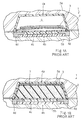
- the prior art process starts with preparation of a split-type mold 1, component members of the ski, a expandable flexible tubular member 2, an upper reinforcing sheet member 3 of metal and a foamable material such as polyurethane foam.
- the component members are assembled into an upper structure 4a in a cavity of an upper mold half 5a and a lower structure 4b in a cavity of a lower mold half 5b.
- the lower structure 4b has a running surface 4c and sole edge members 4d, and will form a hollow space 6 together with the upper structure 4b upon assembly of the split-type mold.
- the expandable flexible tubular member 2 is placed on the lower structure 4b, and the upper reinforcing sheet member 3 is laminated on the expandable flexible tubular member 2.
- the upper mold half 5a is assembled with the lower mold half 5b. Then, the hollow space 6 takes place between the upper structure 4a and the lower structure 4b, and the expandable flexible tubular member 2 and the upper reinforcing sheet member 3 are confined in the hollow space 6 as shown in figure 1A.
- the polyurethane foam is injected into the expandable flexible tubular member 2, and the flexible tubular member 2 expands in the hollow space 6.
- the injection path is formed in the mold 1, and is usually located at one end portion in the longitudinal direction of the ski.
- the polyurethane foam topographically presses the flexible tubular member 2 directly against the inner surfaces of the upper/lower structures 4a/4b and through the upper reinforcing sheet member 3 against the upper structure 4a as shown in figure 1B.
- the polyurethane foam forms a core member 7 filling the space 6.
- the reinforcing sheet member 3 is replaceable with a reinforcing flexible sheet member 8 as shown in figure 2.
- the mold halves 5a and 5b may be inverted as shown in figure 3, and prepregs 8a, 8b and 8c may be used as the reinforcing members.
- the prepregs 8a, 8b and 8c are covered into fiber-reinforced plastic resin layers through heat treatment.
- the prior art process encounters a problem in that the strength of the core member 6 is not constant. This is because of the fact that the urethane foam does not uniformly spread over the inner space of the mold 1. Another reason for the insufficient strength is uncontrollable expansion of the flexible tubular member 2 in the mold 1. While the urethane foam is expanding in the flexible tubular member 2, the flexible tubular member 2 moves the reinforcing member 3, and changes the original relative location between the reinforcing member 3 and the mold 1. This results in a stress concentration and undesirable damage of the reinforcing member 3. If the upper and lower reinforcing members are the prepregs 8a, 8b and 8c, void tends to take place in the fiber-reinforced plastic resin layers, and deteriorates the ski.
- Another problem inherent in the prior art process is the complicated mold 1 due to an injection path for the polyurethane foam, and the complicated mold 1 increases the production cost.
- an upper structure 10a and a lower structure 10b are separately assembled.
- a core member 10c, an upper reinforcing member 10d of fiber-reinforced plastic resin laminated on the upper and side surfaces of the core member 10c and an inverted U-shaped surface member 10e encapsulating the upper reinforcing member 10d and the core member 10c form in combination the upper structure 10a.
- the lower structure 10b includes a lower reinforcing member 10f of fiber-reinforced plastic resin, a sliding plate member 10g attached to the lower surface of the lower reinforcing member 10f and sole edge members 10h attached to both sides of the sliding plate member 10g.
- At least one of the upper and lower reinforcing members 10d and 10f is a laminations of bias sheets, and the reinforcing fibers of the bias sheets extend at 45 degrees and at -45 degrees with respect to the longitudinal direction of the ski.
- the bias sheets enhance the torsional rigidity of the ski.
- the upper and lower structures 10a and 10b thus prepared are bonded in such a manner that the lower surface of the core member 10c is held in contact with the upper surface of the lower reinforcing member 10f.
- the second prior art process may be free from the problems due to the injection of the polyurethane.
- a problem is encountered in the second fabrication process in that the upper structure is liable to be separated from the lower structure due to sharing force resulted from undesirable large bending during the sliding on snow. This is dangerous.
- the present invention proposes to internally produce foam from a foamable gum substance.
- a process of fabricating a ski comprising the steps of: a) preparing a mold having a hollow space similar in configuration to the ski, a first member for providing an outer surface of the ski, a second member for a reinforcing component, a third member of foamable gum substance and components of a lower structure for producing sole edges and a sliding surface; b) assembling the second member and the third member with the first member and the components of the lower structure in the hollow space; c) foaming the foamable gum substance so as to expand in a space defined by the first member and the lower structure; d) setting the foam so as to fill the space with a core member and the reinforcing component, thereby completing the ski; and e) taking out the ski from the mold.
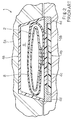
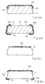
- a ski 20 fabricated through a process embodying the present invention comprises a generally inverted U-shaped surface member 21 defining an upper surface and side surfaces of the ski 20, and embosses 21a and 21b are formed in the upper portion of the surface member 21.
- the embosses 21a and 21b extend in a longitudinal direction of the ski 20.
- the surface member 21 is, by way of example, formed of polyamide elastomer, PET resin, ABS resin, polyvinyl chloride or ionomer.
- the ski 20 further comprises a sliding surface member 22 providing a lower surface of the ski 20 and sole edge members 23a and 23b attached to both sides of the sliding surface member 22.
- the sliding surface member 22 is formed of polyethylene, and a skier presses the sliding surface member 22 to snow.
- the generally inverted U-shaped surface member 21 is terminated at both sides thereof at the sole edge members 23a and 23b, and is integral with the sole edge members 23a and 23b.
- the generally inverted U-shaped surface member 21, the sliding surface member 22 and the sole edge members 23a and 23b form an inner space.
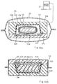
- the ski 20 further comprises a core member 24 formed from foamable substance, a partition sheet 25 topographically enclosing the core member 24 and a reinforcing member 26 of fiber-reinforced plastic resin filling a gap between the inner surface of the generally inverted U-shaped surface member 21 and the core member 24.
- the combined structure of the generally inverted U-shaped surface member 21, the core member 24, the partition sheet 25 and the reinforcing member 26 is made from an upper structure 27 as will be described hereinlater.
- the sliding surface member 22 and the sole edge members 23a and 23b as a whole constitute a lower structure 28.
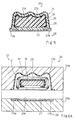
- the process starts with preparation of the members of the upper and lower structures 27 and 28 and a split-type mold 29.
- the split-type mold 29 is constituted by molding halves 29a and 29b, and the molding halves 29a and 29b are separated from one another for assembling the upper and lower structures 27 and 28 in cavities 29c/29d of the molding halves 29a/29b.
- an elongated piece 31 of foamable gum substance is partially wrapped in the partition sheet 25, and the elongated piece 31 of foamable gum substance and the partition sheet 25 is enclosed in a raw member 32 for the fiber-reinforced plastic resin.
- the partition sheet 25 is shorter than the periphery of the elongated piece 31 of foamable gum substance.
- matrix fibers of the raw member 32 is in the same synthetic resin system as the foamable gum substance, and the adhesion is enhanced because of the concurrent thermo-set.
- foamable gum substance means substance which is plastically deformable at room temperature and foamable at a temperature higher than the room temperature.
- the raw member 32 is shaped into a tubular configuration, and the tubular configuration enhances the torsional rigidity of the raw member 32.
- the tubular raw member 32 is formed from a lamination of non-set matrix fibers and reinforcing fibers or a prepreg where matrix resin is impregnated into reinforcing fibers.
- the matrix resin is, by way of example, formed of thermosetting synthetic resin such as, for example, epoxy, vinyl ester resin, polyester resin.
- Thermoplastic resin is also available for the matrix, and the non-set matrix may be in the form of pellet or powder.
- the reinforcing fibers are, by way of example, carbon fibers, glass fibers, aramid fibers or metallic fibers, these fibers may be selectively mixed.
- the first example of the foamable gum substance is in the epoxy system, and contains 40 parts by weight of bisphenol A liquid epoxy resin, 60 parts by weight of bisphenol A solid epoxy resin, 10 parts by weight of setting agent such as, for example, dicyan-diamide, 8 parts by weight of setting promoter such as, for example, dichlorophenyl-dimethylurea and 30 parts by weight of foaming agent such as thermal expansion micro-capsules.
- the expansion ratio is regulated to 8.
- the second example of the foamable gum substance is in the epoxy system, and contains 50 parts by weight of bisphenol A liquid epoxy resin, 50 parts by weight of bisphenol A solid epoxy resin, 18 parts by weight of setting agent, i.e., 8 parts by weight of amine adduct and 10 parts by weight of dicyandiamide (DICY) and 8 parts by weight of foaming agent such as, for example, hydroxybenzenesulfonilhydrazide (OBSH).
- the expansion ratio is regulated to 8.
- the second example may further contain 8 parts by weight of foaming promoter in urea system so as to lower the foaming temperature, and 5 parts by weight of protecting agent such as, for example, barium stearate or polysiloxane bonded to organic functional group so as to prevent cells from breakage during the foaming stage.
- foaming promoter in urea system so as to lower the foaming temperature
- protecting agent such as, for example, barium stearate or polysiloxane bonded to organic functional group so as to prevent cells from breakage during the foaming stage.
- the third example of the foamable gum substance is the epoxy system, and contains 100 parts by weight of bisphenol A liquid epoxy resin, 20 parts by weight of latent low-temperature setting agent such as amine adduct and 8 parts of foaming agent such as, for example, hydroxybenzenesulfonilhydrazide (OBSH).
- OBSH hydroxybenzenesulfonilhydrazide
- the foaming is carried out around 80 degrees centigrade for 10 minutes, and, thereafter, the foam is cooled.
- the expansion ratio is regulated to 8.
- the third example may further contain 8 parts by weight of foaming promoter in urea system so as to lower the foaming temperature.
- the fourth example of the foamable gum substance is in the polyester system, and contains 100 parts by weight of unsaturated polyester resin, 20 parts by weight of setting catalyst such as peroxide, 30 parts by weight of thermally expanding micro-capsules and 3 parts of viscosity increaser such as, for example, calcium hydroxide.
- the expansion ratio is also regulated to 8.
- Glass balloon, ceramic balloon or phenol balloon may be added to the first to fourth examples of the foamable gum substance so as to increase the volume of the elongated piece 31 of foamable gum substance.
- the density of foamable gum substance is preferably regulated to 0.65.
- the amount of foamable gum substance in the cavity 29c is regulated in such a manner as to generate pressure ranging from 8 kg/cm2 to 10 kg/cm2.
- the partition sheet 25 is, by way of example, formed of valcanized gum, elastomer in urethane system, elastomer in ester system or elastomer in polyamide system.
- the gum or the elastomer is required to be not less than 100 percent in elongation percentage before break, not less than 10 MPa in tensile strength, not less than 130 degrees centigrade in fusion point and 0.05 to 0.40 millimeter in thickness. If a substance has the elongation percentage not less than 200 percent and the tensile strength not less than 20 MPa, the substance is more preferable.
- the mold 29 is heated to 120 degrees centigrade, and is maintained for 35 minutes. Then, the heat foams the gum substance, and converts the raw member 25 to the reinforcing member 26 of fiber-reinforced plastic resin. While the foam is expanding in the inner space of the mold 29, the partition sheet 25 and the raw member 32 are outwardly moved, and are pressed to the inner surface of the surface member 21. Therefore, the reinforcing member 26 is topographical along the inner surface of the surface member 21, and the reinforcing member 25, the partition sheet 25 and the core member 24 fill the inner space among the surface member 21, the sliding surface member 22 and the sole edge members 23a/23b.
- the elongated piece 31 of foamable gum substance occupies the inner space among the surface member 21, the sliding surface member 22 and the sole edge members 23a and 23b, and uniformly supplies the foam. As a result, a void hardly takes place in the core member 24, and the core member 24 provides uniform strength along the longitudinal direction. Moreover, the air in the cavities is evacuated through abutting surfaces of the molding halves 29a and 29b before the foaming, because the raw member 32 encloses the elongated piece 31 of foamable gum substance.
- the partition sheet 25 causes the reinforcing member 26 to be closely held in contact with the inner surface of the surface member 21, and the matrix of the reinforcing member 26 is merged with the core member 24 because of the same synthetic resin system.
- the surface member 21 is integrated with the lower structure 28 during the heat treatment, and is never separated from the lower structure 28 during the skiing.
- the foam When 35 minutes pass, the foam is thermally set, and is converted to the core member 24.
- the core member 24, the partition sheet 25 and the reinforcing member 26 snugly fill the inner space of the mold 29, and the surface member 21 is integrated with the lower structure 28.
- the mold 29 is cooled by using water at 15 degrees centigrade for 10 minutes, and reaches room temperature equal to or less than 30 degrees centigrade.
- the ski 20 is completed in the mold 29 as shown in figure 6C, and the molding halves 29a and 29b are separated so as to take out the ski 20 from the mold 29.
- the foam is internally produced in the mold 29, and the ski 20 is free from a burr due to the injection. A grinding stage for the burr is not necessary, and the production cost is further decreased.
- the foam uniformly generated from the gum substance eliminates a void from the core member 24, and the ski 20 is stronger than the prior art ski.
- the gum substance is exactly placed in the mode, and, accordingly, the foam uniformly presses the other components such as the raw member 32 to the inner surface of the surface member 21 and the sliding surface member 22 without undesirable movement. This feature further enhances the strength of the ski.
- the mold is simple, and no additional work is necessary for a burr. This results in reduction of the production cost.
- the ski 20 integrated in the mold 29 is free from undesirable separation, and is safety.
- two kinds of foamable gum substance may be used for two-layered core member structure made from a laminated structure 41a/41b of foamable gum substance.
- the core members are different in compressive rigidity.
- a lower elongated piece 41b of foamable gum produces foam for the hard core member, and an upper elongated piece 41a of foamable gum generates foam for the soft core member.
- the hard core member maintains a smooth sliding surface, and the soft core member takes up the shock from the snow ground to the skier.
- Figure 8 illustrates a second modification, and a core structure is constituted by soft and hard core members arranged in parallel.
- the soft core member is made from an elongated piece 42a of first kind of foamable gum substance, and occupies the outside of the ski.
- the hard core member is made from an elongated piece 42b of second kind of foamable gum substance, and occupies the inside of the ski.
- the ski equipped provides a sharp inside edging and a soft outside edging to a skier.
- Figure 9 illustrates a third modification, and a hard core member is sandwiched between soft core members.
- the hard core member is made from an elongated piece 43a of first kind of foamable gum substance, and the soft core members are made from elongated pieces 43b and 43c of second kind of foamable gum substance.
- the hard core member maintains a smooth sliding surface, and the soft core members provides the soft inside/outside edging to a skier.
- Figure 10 illustrates a fourth modification, and a soft core member is wrapped by a hard core member.
- the soft core member is made from an elongated piece of second kind of foamable gum substance, and the hard core member is made from an elongated tube 44b of first kind of foamable gum substance.
- the hard core member maintains a smooth sliding surface, and the soft core member makes the ski light.
- Figure 11 illustrates a fifth modification, and soft core members are merged with the front end portion and the rear end portion of a hard core member.
- the hard core member is made from an elongated piece 45a of first kind of foamable gum substance
- the soft core members are made from elongated pieces 45b and 45c of second kind of foamable gum substance.
- the soft core members provide easily deformable front and rear end portions to the ski, and makes the ski light.
- the hard core member in the central portion of the ski improves the durability of the ski.
- the soft core members contiguous to the hard core member change the flex pattern of the ski.
- the foaming gum substance is converted to both soft and hard core members, and the soft and hard core members are different in compressive rigidity.
- the soft and hard core members allows the manufacturer to arbitrarily regulate the characteristics of the ski.
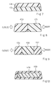
- partition sheet 25 partially wraps the elongated piece 31 of foamable gum substance except for the central area of the bottom surface, various modifications are employable as shown in figures 12A to 12D.
- figure 12A shows the first modification 46a of the partition sheet 25.
- the first modification 46a extends on the upper surface of the elongated piece 31, and both side portions covers both upper corners 31a and 31b of the elongated piece 31.
- the second modification is implemented by two parts 46.
- One of the two parts 46 extends from the upper corner 31a through the left side surface to the lower corner 31c, and the other part 46 covers the other upper corner 46b, the right side surface and the lower corner 31d.
- the third modification 46c simply covers the upper surface of the elongated piece 31 of foamable gum substance.
- the fourth modification is implemented by three parts 46d.
- the first part 46d is similar to the first modification 46a, and the second and third parts 46d covers the lower corners 31c and 31d.
- the raw member 32 is shaped into a tubular configuration.
- the first modification of the raw member 32 is a flexible sheet, and the flexible sheet is wound on the entire surface of the elongated piece 31.
- FIG 13 illustrates the structure of a ski fabricated through a process embodying the present invention.
- the ski largely comprises an upper structure 51 and a lower structure 52, and the upper structure 51 is integral with the lower structure 52.
- the upper structure 51 includes a surface member 51a shaped into a generally inverted U-configuration, a reinforcing member 51b of fiber-reinforced plastic resin and a core member 51c of foam plastic resin.
- the reinforcing member 51b is closely held in contact with the inner surface of the surface member 51a, and the core member 51c is snugly received in an inner space of the reinforcing member 51b.
- the lower structure 52 includes a sliding surface member 52a and sole edge members 52b and 52c attached to both sides of the sliding surface member 52a.
- the bottom surface of the sliding surface portion 52a is pressed against snow, and slides on the snow ground.
- the sliding surface member 52a is formed of high molecular polyethylene resin, and the polyethylene resin tends to be deformed over 120 degrees centigrade.
- the lower portion of the reinforcing member 51b is fixed to the upper surface of the sliding surface member 52a, and the side portions of the surface member 51a are fixed to the upper surfaces of the sole edge members 52b and 52c, respectively.
- the upper structure 51 is integrated with the lower structure 52.
- the process sequence is described hereinbelow with reference to figures 14A to 14D.
- the process starts with preparation of a mold 53, the surface member 51a, an elongated piece 55 of foamable gum substance, a flexible matrix sheet 55a, a tubular fabric member 55b made from reinforcing fibers, the sliding surface member 52a and sole edge members 52b and 52c.
- the foamable gum substance is plastically deformable at room temperature, and heat foams the foamable gum substance.
- the tubular fabric member 55b may contain reinforcing fibers woven into a tube.
- the flexible matrix sheet 55a and the tubular fabric member 55b form in combination a raw member 55 for the reinforcing member 51c.
- the surface member 51a is, by way of example, formed of polyamide elastomer, PET resin, ABS resin, polyvinyl chloride or ionomer.
- the matrix resin is thermo-setting synthetic resin good in tack and drape at room temperature, and viscosity is preferably 10,000 cp at 60 degrees centigrade and hundreds cp at 110-120 degrees centigrade. Nylon and polycarbonate are not available, because they are solid at 120 degrees centigrade.
- the reinforcing fibers are woven into the tube of the tubular fabric member 55b, a non-woven fabric is available, and the configuration is not limited to the tube.
- the reinforcing fibers are, by way of example, carbon fibers, glass fibers, aramid fibers or metallic fibers, or these fibers may be selectively mixed.
- the first example of the foamable gum substance is in the epoxy system, and contains 50 parts by weight of bisphenol A liquid epoxy resin, 60 parts by weight of bisphenol A solid epoxy resin, 10 parts by weight of setting agent such as, for example, dicyan-diamide, 8 parts by weight of setting promoter such as, for example, dichlorophenyl-dimethylurea and 30 parts by weight of foaming agent such as thermal expansion micro-capsules.
- the expansion ratio is regulated to 8.
- the second example of the foamable gum substance is in the epoxy system, and contains 50 parts by weight of bisphenol A liquid epoxy resin, 50 parts by weight of bisphenol A solid epoxy resin, 18 parts by weight of setting agent, i.e., 8 parts by weight of amine adduct and 10 parts by weight of dicyandiamide (DICY) and 8 parts by weight of foaming agent such as, for example, hydroxybenzenesulfonilhydrazide (OBSH).
- the expansion ratio is regulated to 8.
- the second example may further contain 8 parts by weight of foaming promoter in urea system so as to lower the foaming temperature, and 5 parts by weight of protecting agent such as, for example, barium stearate or polysiloxane bonded to organic functional group so as to prevent cells from breakage during the foaming stage.
- foaming promoter in urea system so as to lower the foaming temperature
- protecting agent such as, for example, barium stearate or polysiloxane bonded to organic functional group so as to prevent cells from breakage during the foaming stage.
- the third example of the foamable gum substance is the epoxy system, and contains 100 parts by weight of bisphenol A liquid epoxy resin, 20 parts by weight of latent low-temperature setting agent such as amine adduct and 8 parts of foaming agent such as, for example, hydroxybenzenesulfonilhydrazide (OBSH).
- OBSH hydroxybenzenesulfonilhydrazide
- the foaming is carried out around 80 degrees centigrade for 10 minutes, and, thereafter, the foam is cooled.
- the expansion ratio is regulated to 8.
- the third example may further contain 8 parts by weight of foaming promoter in urea system so as to lower the foaming temperature.
- the fourth example of the foamable gum substance is in the polyester system, and contains 100 parts by weight of unsaturated polyester resin, 20 parts by weight of setting catalyst such as peroxide, 30 parts by weight of thermally expanding micro-capsules and 3 parts of viscosity increaser such as, for example, calcium hydroxide.
- the expansion ratio is also regulated to 8.
- Glass balloon, ceramic balloon or phenol balloon may be added to the first to fourth examples of the foamable gum substance so as to increase the volume of the elongated piece 54 of foamable gum substance.
- the density of foamable gum substance is preferably regulated to 0.65.
- the amount of foamable gum substance in the cavity 53c is regulated in such a manner as to generate pressure ranging from 8 kg/cm2 to 10 kg/cm2.
- the elongated piece 54 of foamable gum substance is inserted into an inner space of the tubular fabric member 55b, and the flexible matrix sheet 55a is wound on the tubular fabric member 55b as shown in figure 14A.
- the mold 53 is a split-type, and molding halves 53a and 53b constitute the split-type mold 53.
- the molding half 53a has a cavity 53c corresponding to the outer configulation of the upper structure 51, and a cavity 53d in the other molding half 53d corresponds to the outer configuration of the lower structure 52.
- the surface member 51a is inserted into the cavity 53c, and the flexible matrix sheet 55a and the tubular fabric member 55b wound on the elongated piece 54 is put on the inner surface of the surface member 51a.
- the sliding surface member 52a is placed in the cavity 53d, and the sole edge members 52b and 52c are provided in the gaps between the molding half 53b and the sliding surface member 52a.
- figure 14B illustrates the molding half 53b over the molding half 53a
- the molding halves 53a adn 53b may be placed on a working table in such a manner as to upwardly direct the cavities 53c and 53d during the asemblage.
- the molding halves 53a and 53b are opposed to each other as shown in figure 14B, and are assembled together.
- the mold 53 is enclosed in a flexible package 56, and is sealed therein.
- the inner space of the flexible package 56 is conencted to a vacuum source 57, and the air is evacuated from the inner space of the flexible package 56.
- the molding halves 53a and 53b are closely assembled inside the flexible package 56.
- the flexible package 56 is, by way of example, formed of polyamide resin or from a lamination of polyamide resin/polyethylene, EVA resin/polyethylene, polyamide resin/ionomer or polyamide/EVA resin.
- the mold 53 is heated to 100 - 120 degrees centigrade in vacuum for 35 minutes.
- the heat foams the elongated piece 54, and the foam outwardly presses the tubular fabric member 55b to the flexible matrix sheet 55a.
- the heat further melts the flexible matrix sheet 54a, and the tubular fabric member 55b is impregnated with the matrix resin.
- the foam further presses the tubular fabric member 55b impregnated with the matrix resin to expand, and presses the tubular fabric member 55b against the surface member 51a, the sliding surface member 52a and the sole edge members 52b and 52c.
- the foam is hardened, and is coverted to the core member 51c.
- the mold 53 is cooled in water at 15 degrees centigrade for 10 minutes.
- the tubular fabric member 55b impregnated with the matrix resin is hardened, and the reinforcing member 51b fills the gap between the core member 51c and the surface member 51a/the sliding surface member 52a/the sole edge members 52b and 52c as shown in figure 14D.
- the sliding surface member 52a of high molecular polyethylene resin sets the limit on the highest temperature of the heat treatment, and the tubular fabric member 55b is expected to be impregnated with the matrix resin at not higher than 120 degrees centigrade. If the reinforcing member 51b is made from a prepreg, the reinforcing fibers may not sufficiently impregnated with the matrix resin at 120 degrees. However, the flexible matrix sheet 55a is melted and sufficiently impregnated into the reinforcing fibers by virtue of the laminated structure.
- the mold 53 is taken out from the package 56, and the molding halves 53a and 53b are separated from one another.
- the ski shown in figure 13 is completed in the cavity 53c.
- a press machine may presses the molding halves 53a and 53b to each other during the heat treatment.
- the pressing conditions are 2 kg/cm2 x 2 minutes as an open pressure and 10 - 12 kg/cm2 x ST as a main pressure.
- ST means time period for setting the resin.
- the elongated piece 54 may be formed of more than one kind of foamable gum substance as similar to the first embodiment.
- Matrix resin sheets may be attached to the components of the upper/lower structures 51 and 52 instead of the flexible matrix sheet wound on the elongated piece 54.
- the elongated piece 54 of foamable gum substance internally produces the foam, and all the advantages of the first embodiment is also achieved by the second embodiment.
- the elongated piece 54 is inserted into the tubular fabric member 55b, and the relative position therebetween is hardly varied in the mold 53. Even if the elongated piece 54 is not a simple configuration, the tubular fabric member 55b follows the elongated piece 54, and topographically wound on the elongated piece 54. Therefore, the reinforcing fibers of the member 51b are oriented to designed direction or directions, and relatively small amount of reinforcing fibers imparts large strength to the ski.
- the sliding surface member 52a and the sole edge members 52b and 52c are hardly separated from the core member 51c, because they are integrated in the mold 53.
- liquid foamable substance hardly makes the bias sheet conformal to a complicated inner surface of the mold, because the pressure passes through the sleeve-shaped bias sheet to the complicated inner surface of the mold.
- the foamable gum substance effectively presses the sleeve-shaped bias sheet against the complicated inner surface of the mold, and causes the sleeve-shaped bias sheet to become conformal to the complicated inner surface of the mold. This results in large mechanical strength.
- the process parameters are variable depending upon the substances of the components.
- the sliding surface member is usually formed of high molecular polyethylene resin, and the mold is heated to any temperature in so far as the sliding surface member is not deformed due to the heat.
Landscapes
- Polymers With Sulfur, Phosphorus Or Metals In The Main Chain (AREA)
- Polymerisation Methods In General (AREA)
- Laminated Bodies (AREA)
- Treatments For Attaching Organic Compounds To Fibrous Goods (AREA)
- Gloves (AREA)
- Casting Or Compression Moulding Of Plastics Or The Like (AREA)
- Footwear And Its Accessory, Manufacturing Method And Apparatuses (AREA)
Applications Claiming Priority (6)
| Application Number | Priority Date | Filing Date | Title |
|---|---|---|---|
| JP230704/94 | 1994-08-31 | ||
| JP23070494 | 1994-08-31 | ||
| JP6230704A JP2847472B2 (ja) | 1994-08-31 | 1994-08-31 | スキー板の製法 |
| JP266341/94 | 1994-10-05 | ||
| JP26634194 | 1994-10-05 | ||
| JP6266341A JP2847474B2 (ja) | 1994-10-05 | 1994-10-05 | スキー板の製法 |
Publications (3)
| Publication Number | Publication Date |
|---|---|
| EP0699458A2 true EP0699458A2 (de) | 1996-03-06 |
| EP0699458A3 EP0699458A3 (de) | 1996-04-17 |
| EP0699458B1 EP0699458B1 (de) | 2000-01-19 |
Family
ID=26529484
Family Applications (1)
| Application Number | Title | Priority Date | Filing Date |
|---|---|---|---|
| EP95113630A Expired - Lifetime EP0699458B1 (de) | 1994-08-31 | 1995-08-30 | Verfahren zur Herstellung eines starken und zuverlässigen Skis |
Country Status (3)
| Country | Link |
|---|---|
| EP (1) | EP0699458B1 (de) |
| AT (1) | ATE188879T1 (de) |
| DE (1) | DE69514591T2 (de) |
Cited By (2)
| Publication number | Priority date | Publication date | Assignee | Title |
|---|---|---|---|---|
| FR2766099A1 (fr) * | 1997-07-21 | 1999-01-22 | Rossignol Sa | Procede de fabrication d'un noyau constituant l'ame d'une planche de glisse sur neige |
| FR2879939A1 (fr) * | 2004-12-29 | 2006-06-30 | Salomon Sa | Procede de fabrication d'une planche de glisse ou de roulage a structure composite |
Families Citing this family (1)
| Publication number | Priority date | Publication date | Assignee | Title |
|---|---|---|---|---|
| EP3335771A1 (de) * | 2016-12-19 | 2018-06-20 | Francesco Meneghello | Wintersportausrüstung mit einem körper und herstellungsverfahren dafür |
Citations (2)
| Publication number | Priority date | Publication date | Assignee | Title |
|---|---|---|---|---|
| JPH01284272A (ja) | 1988-03-29 | 1989-11-15 | Salomon Sa | スキー板の製作方法およびこの方法によって作られたスキー板 |
| JPH03182275A (ja) | 1989-11-22 | 1991-08-08 | Salomon Sa | 射出成形によるスキー板の製造方法およびこの方法によって製造したスキー板の構造 |
Family Cites Families (4)
| Publication number | Priority date | Publication date | Assignee | Title |
|---|---|---|---|---|
| AT296105B (de) * | 1969-01-17 | 1972-01-25 | Albert Bader | Schi |
| AT384171B (de) * | 1985-04-03 | 1987-10-12 | Gerhard Dr Watschinger | Ski od. dgl. |
| DE3545455A1 (de) * | 1985-12-20 | 1987-07-02 | Jochen Adamek | Verfahren zur herstellung von thermoplastischen koerpern mit kern |
| AT400679B (de) * | 1990-03-09 | 1996-02-26 | Atomic Austria Gmbh | Schi |
-
1995
- 1995-08-30 AT AT95113630T patent/ATE188879T1/de not_active IP Right Cessation
- 1995-08-30 EP EP95113630A patent/EP0699458B1/de not_active Expired - Lifetime
- 1995-08-30 DE DE69514591T patent/DE69514591T2/de not_active Expired - Fee Related
Patent Citations (2)
| Publication number | Priority date | Publication date | Assignee | Title |
|---|---|---|---|---|
| JPH01284272A (ja) | 1988-03-29 | 1989-11-15 | Salomon Sa | スキー板の製作方法およびこの方法によって作られたスキー板 |
| JPH03182275A (ja) | 1989-11-22 | 1991-08-08 | Salomon Sa | 射出成形によるスキー板の製造方法およびこの方法によって製造したスキー板の構造 |
Cited By (3)
| Publication number | Priority date | Publication date | Assignee | Title |
|---|---|---|---|---|
| FR2766099A1 (fr) * | 1997-07-21 | 1999-01-22 | Rossignol Sa | Procede de fabrication d'un noyau constituant l'ame d'une planche de glisse sur neige |
| FR2879939A1 (fr) * | 2004-12-29 | 2006-06-30 | Salomon Sa | Procede de fabrication d'une planche de glisse ou de roulage a structure composite |
| AT501188B1 (de) * | 2004-12-29 | 2008-09-15 | Salomon Sa | Gleit- oder rollbrett mit verbundstruktur und verfahren zu seiner herstellung |
Also Published As
| Publication number | Publication date |
|---|---|
| DE69514591T2 (de) | 2000-08-03 |
| DE69514591D1 (de) | 2000-02-24 |
| ATE188879T1 (de) | 2000-02-15 |
| EP0699458A3 (de) | 1996-04-17 |
| EP0699458B1 (de) | 2000-01-19 |
Similar Documents
| Publication | Publication Date | Title |
|---|---|---|
| US5273696A (en) | Process of forming a ski by injection | |
| JPH0763519B2 (ja) | 射出成形によるスキー板の製造方法およびこの方法により製造したスキー板の構造 | |
| EP2990186B1 (de) | Verfahren zur herstellung eines geformten bauteils enthaltend einen epoxidkern mit expandierbaren mikrosphären | |
| US3867221A (en) | Preparing an article of thermosetting resin | |
| US5080851A (en) | Method for stabilizing complex composite preforms | |
| US20060064904A1 (en) | Sports boot in very stiff material | |
| KR20030063162A (ko) | 경질 지지체 및 연질 중공부재를 갖는 성형제품 | |
| WO2001021024A1 (en) | Air cushion having support pin structure for shock-absorbing, method for manufacturing the air cushion, and footgear comprising the air cushion | |
| JPH10338082A (ja) | 自動車用ルーフ・ヘッド・ライナー | |
| US7732044B2 (en) | Foam core-surface reinforced article and method | |
| US5122210A (en) | Process for producing a bicycle frame made of fiber-reinforced plastics | |
| WO2006042422A1 (en) | Hockey stick blade and a method of making thereof | |
| JP2011524832A (ja) | 車両用ボディシェル構造及びその製造方法 | |
| CA2031863A1 (en) | Fiber-reinforced foamed material and method of producing it | |
| EP1220764A1 (de) | Türinnenverkleidung mit sandwichstruktur | |
| EP0699458B1 (de) | Verfahren zur Herstellung eines starken und zuverlässigen Skis | |
| US5501825A (en) | Process for the manufacture of a shaped ski | |
| WO2021237365A1 (en) | Skate or other footwear | |
| US20060145506A1 (en) | Control panel and method for the production thereof | |
| EP0415869B1 (de) | Stabilisierung von Einlagen für das "RTM"-Verfahren | |
| US20040100068A1 (en) | Gliding board and method for manufacture of such a gliding board | |
| JP2762006B2 (ja) | バドミントン用ラケットフレームの成形方法 | |
| ES2122422T3 (es) | Suela para calzado deportivo y procedimiento de fabricacion de dicha suela. | |
| JPH0739404A (ja) | スポーツシューズ | |
| JPH02251427A (ja) | 多孔織物弾性体及びその製造方法 |
Legal Events
| Date | Code | Title | Description |
|---|---|---|---|
| PUAI | Public reference made under article 153(3) epc to a published international application that has entered the european phase |
Free format text: ORIGINAL CODE: 0009012 |
|
| PUAL | Search report despatched |
Free format text: ORIGINAL CODE: 0009013 |
|
| AK | Designated contracting states |
Kind code of ref document: A2 Designated state(s): AT DE FR |
|
| AK | Designated contracting states |
Kind code of ref document: A3 Designated state(s): AT DE FR |
|
| 17P | Request for examination filed |
Effective date: 19961017 |
|
| 17Q | First examination report despatched |
Effective date: 19961217 |
|
| GRAG | Despatch of communication of intention to grant |
Free format text: ORIGINAL CODE: EPIDOS AGRA |
|
| EL | Fr: translation of claims filed | ||
| TCAT | At: translation of patent claims filed | ||
| GRAG | Despatch of communication of intention to grant |
Free format text: ORIGINAL CODE: EPIDOS AGRA |
|
| GRAH | Despatch of communication of intention to grant a patent |
Free format text: ORIGINAL CODE: EPIDOS IGRA |
|
| RAP1 | Party data changed (applicant data changed or rights of an application transferred) |
Owner name: JAPANA CO., LTD. |
|
| GRAH | Despatch of communication of intention to grant a patent |
Free format text: ORIGINAL CODE: EPIDOS IGRA |
|
| GRAA | (expected) grant |
Free format text: ORIGINAL CODE: 0009210 |
|
| AK | Designated contracting states |
Kind code of ref document: B1 Designated state(s): AT DE FR |
|
| REF | Corresponds to: |
Ref document number: 188879 Country of ref document: AT Date of ref document: 20000215 Kind code of ref document: T |
|
| REF | Corresponds to: |
Ref document number: 69514591 Country of ref document: DE Date of ref document: 20000224 |
|
| ET | Fr: translation filed | ||
| PLBE | No opposition filed within time limit |
Free format text: ORIGINAL CODE: 0009261 |
|
| STAA | Information on the status of an ep patent application or granted ep patent |
Free format text: STATUS: NO OPPOSITION FILED WITHIN TIME LIMIT |
|
| 26N | No opposition filed | ||
| REG | Reference to a national code |
Ref country code: FR Ref legal event code: TP Ref country code: FR Ref legal event code: CD |
|
| PGFP | Annual fee paid to national office [announced via postgrant information from national office to epo] |
Ref country code: DE Payment date: 20060706 Year of fee payment: 12 |
|
| PGFP | Annual fee paid to national office [announced via postgrant information from national office to epo] |
Ref country code: FR Payment date: 20060717 Year of fee payment: 12 |
|
| PGFP | Annual fee paid to national office [announced via postgrant information from national office to epo] |
Ref country code: AT Payment date: 20060724 Year of fee payment: 12 |
|
| PG25 | Lapsed in a contracting state [announced via postgrant information from national office to epo] |
Ref country code: AT Free format text: LAPSE BECAUSE OF NON-PAYMENT OF DUE FEES Effective date: 20070830 |
|
| REG | Reference to a national code |
Ref country code: FR Ref legal event code: ST Effective date: 20080430 |
|
| PG25 | Lapsed in a contracting state [announced via postgrant information from national office to epo] |
Ref country code: DE Free format text: LAPSE BECAUSE OF NON-PAYMENT OF DUE FEES Effective date: 20080301 |
|
| PG25 | Lapsed in a contracting state [announced via postgrant information from national office to epo] |
Ref country code: FR Free format text: LAPSE BECAUSE OF NON-PAYMENT OF DUE FEES Effective date: 20070831 |