EP0699552A2 - Dispositif pour l'actionnement manuel de la pédale d'accélérateur d'un véhicule à moteur - Google Patents
Dispositif pour l'actionnement manuel de la pédale d'accélérateur d'un véhicule à moteur Download PDFInfo
- Publication number
- EP0699552A2 EP0699552A2 EP95113151A EP95113151A EP0699552A2 EP 0699552 A2 EP0699552 A2 EP 0699552A2 EP 95113151 A EP95113151 A EP 95113151A EP 95113151 A EP95113151 A EP 95113151A EP 0699552 A2 EP0699552 A2 EP 0699552A2
- Authority
- EP
- European Patent Office
- Prior art keywords
- potentiometer
- servomotor
- control unit
- regulating
- actuating
- Prior art date
- Legal status (The legal status is an assumption and is not a legal conclusion. Google has not performed a legal analysis and makes no representation as to the accuracy of the status listed.)
- Granted
Links
Images


Classifications
-
- B—PERFORMING OPERATIONS; TRANSPORTING
- B62—LAND VEHICLES FOR TRAVELLING OTHERWISE THAN ON RAILS
- B62D—MOTOR VEHICLES; TRAILERS
- B62D1/00—Steering controls, i.e. means for initiating a change of direction of the vehicle
- B62D1/02—Steering controls, i.e. means for initiating a change of direction of the vehicle vehicle-mounted
- B62D1/04—Hand wheels
-
- B—PERFORMING OPERATIONS; TRANSPORTING
- B60—VEHICLES IN GENERAL
- B60K—ARRANGEMENT OR MOUNTING OF PROPULSION UNITS OR OF TRANSMISSIONS IN VEHICLES; ARRANGEMENT OR MOUNTING OF PLURAL DIVERSE PRIME-MOVERS IN VEHICLES; AUXILIARY DRIVES FOR VEHICLES; INSTRUMENTATION OR DASHBOARDS FOR VEHICLES; ARRANGEMENTS IN CONNECTION WITH COOLING, AIR INTAKE, GAS EXHAUST OR FUEL SUPPLY OF PROPULSION UNITS IN VEHICLES
- B60K26/00—Arrangement or mounting of propulsion-unit control devices in vehicles
- B60K26/02—Arrangement or mounting of propulsion-unit control devices in vehicles of initiating means or elements
-
- B—PERFORMING OPERATIONS; TRANSPORTING
- B60—VEHICLES IN GENERAL
- B60W—CONJOINT CONTROL OF VEHICLE SUB-UNITS OF DIFFERENT TYPE OR DIFFERENT FUNCTION; CONTROL SYSTEMS SPECIALLY ADAPTED FOR HYBRID VEHICLES; ROAD VEHICLE DRIVE CONTROL SYSTEMS FOR PURPOSES NOT RELATED TO THE CONTROL OF A PARTICULAR SUB-UNIT
- B60W30/00—Purposes of road vehicle drive control systems not related to the control of a particular sub-unit, e.g. of systems using conjoint control of vehicle sub-units
- B60W30/18—Propelling the vehicle
- B60W30/18181—Propulsion control with common controlling member for different functions
-
- B—PERFORMING OPERATIONS; TRANSPORTING
- B60—VEHICLES IN GENERAL
- B60W—CONJOINT CONTROL OF VEHICLE SUB-UNITS OF DIFFERENT TYPE OR DIFFERENT FUNCTION; CONTROL SYSTEMS SPECIALLY ADAPTED FOR HYBRID VEHICLES; ROAD VEHICLE DRIVE CONTROL SYSTEMS FOR PURPOSES NOT RELATED TO THE CONTROL OF A PARTICULAR SUB-UNIT
- B60W2540/00—Input parameters relating to occupants
- B60W2540/10—Accelerator pedal position
Definitions
- the invention relates to a device for manually actuating the accelerator pedal of a motor vehicle with a steering wheel fastened to the steering spindle, furthermore with an actuating wheel which is axially displaceable relative to the steering wheel and rotatable together with it, and with an arrangement for transmitting the axial displacement of the actuating wheel for pedal actuation .
- the actuating wheel can act directly on the power regulator of the motor vehicle engine.
- the Otto engine this is the throttle valve of the carburetor, with the diesel engine, the ice injection pump and with the electric engine, it is an actuator in its power supply.
- manual operation is carried out directly on the accelerator pedal in order to simplify the setup and to keep the vehicle equipped for normal use. Therefore, in the above genre on manual operation referred to the accelerator pedal, but this is not intended to exclude the aforementioned direct power control of the motor vehicle engine.
- the object of the invention is therefore to construct and design a device of the type mentioned at the outset in such a different way that an airbag can be fitted within the steering wheel in the manner customary in series vehicles.
- the device should take up little space in the area of the steering wheel and the steering column and should be easy to retrofit in series vehicles.
- the actuating wheel which is guided axially displaceably on the steering wheel, is connected to the actuating part of a setpoint potentiometer attached to the steering wheel, in that an actuator which can be actuated by an actuating motor attached to the motor vehicle is connected to the accelerator pedal in such a way that the position of the actuator is controlled by a Actual value potentiometer connected to him or the servomotor can be sensed, and that the control motor can be actuated by a regulating and control unit in each case until the values supplied by the potentiometers are compared.
- the subsequent assembly of the device according to the invention is also simple, since practically the entire steering column area, with the exception of the electrical connecting line, remains unaffected, that is to say the input can be made at locations which are easily accessible from the outside.
- the manual actuation of the accelerator pedal according to the invention can be operated without any particular effort, since in addition to the actuating wheel, only the adjusting part of the setpoint potentiometer can be moved, but not an extensive connecting linkage to the accelerator pedal. Therefore, the manual operation according to the invention is also suitable for people whose arms and hands are impaired in their strength.
- the actuating wheel can be guided axially displaceably on the rim of the steering wheel.
- the actuating wheel it has proven to be expedient for the actuating wheel to be guided in at least two axially parallel rods extending from it in a housing fastened to the steering wheel hub. If the actuating wheel then has a rod-shaped chord that traverses it, the rods and the adjusting part of the setpoint potentiometer, the fixed part of which can be arranged on the housing, can emanate from the chord.
- the actuating wheel can be displaced from a rest position, which corresponds to the idling of the motor vehicle engine, against the action of a restoring force, which can be formed by a restoring spring supported on the fixed part of the setpoint potentiometer.
- both training as a linear potentiometer and training as a rotary potentiometer are possible.
- the use of a linear potentiometer should be expedient because of the axial displacement movement of the actuating wheel, which then does not require any additional levers to be implemented on the potentiometer.
- a servomotor which can be driven in both directions, the use of an electric motor being possible for its formation because of the electrical supply which is present anyway.
- a hydraulic motor is also conceivable with regard to the supply of pressure oil that is present at least in motor vehicles with internal combustion engines.
- the actuator of the servomotor is a lever arm which can be pivoted by the servomotor, and that a connecting member extending from the accelerator pedal is articulated at the free end of the lever arm, which is advantageously a rigid component.
- a clutch which can be switched by the regulating and control unit and which can be switched on electrically against the action of a force releasing it can be arranged between the servomotor and the actuator. This ensures that, in the event of a power failure, the accelerator pedal is returned to the idle position under the effect of the normally acting return spring, since the connection between the servomotor and actuator is then interrupted.
- This also ensures that the motor vehicle drive returns to idling in the event of braking or an unforeseen event. So that in one of the cases mentioned the control unit does not continue to attempt to make the servo follow a deflection of the actuating wheel, it can be provided that the control unit can be switched off with respect to the adjustment of the potentiometers during the actuation of the brake light switch and possibly the airbag sensors is.
- a rotary potentiometer or a linear potentiometer can also be considered for the actual value potentiometer.
- a linear potentiometer could work, for example, with the lever arm that can be connected to the servomotor. However, it should be expedient to attach a rotary potentiometer coaxial to the actuator on the actuator.
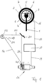
- FIGS 1 and 2 show a steering wheel 2 seated on a steering column 1, in which an actuating wheel 3 is arranged concentrically.
- a housing 5 On the hub 4 of the steering wheel sits a housing 5, via which the actuating wheel 3 is axially displaceable by means of two rods 6 which are essentially perpendicular to the plane of the drawing in FIG.
- the rods 6 are fastened to a chord 7 which crosses the actuating wheel 3 above the steering wheel hub 4.
- the fixed part 8 of a linear potentiometer is seated in or on the housing 5, the adjusting part 9 of which is connected to a tab 10, which is also seated on the chord 7.
- the actuating part 9 is located between the two rods 6.
- a return spring 11 is arranged, which tries to bring the actuating wheel 3 and thus the actuating part 9 into a stop position on the left relative to FIG Motor vehicle engine corresponds.
- the stop position can be formed by the mobility of the adjusting part 9 within the fixed part 8.
- FIG. 2 shows screw connections 12, with which the fixed part 8 on the housing 5 within one there Receiving space 13 is fixed, and a screw 14 for attaching the housing 5 on the steering wheel hub 4th
- An electrical line 15 goes from the linear potentiometer 8, 9 to a slip ring 16 indicated in FIG. 1, from which a line 17 leads to a regulating and control unit 18, which will be discussed in more detail later.
- an electrical connection 19 goes from the regulating and control unit 18 to an actuating unit 20 for the accelerator pedal 21, which in the present case is known in the present case via a connection 22 to the throttle valve 23 of the carburetor of an Otto -Motor is connected.
- a spring 24 engaging the throttle valve 23 ensures that the throttle valve 23 and accelerator pedal 21 are constantly loaded in the sense of a return to the idle position for the vehicle engine.
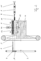
- the actuating unit 20 has a housing 25 with a recess 26 for receiving an actuating motor 27, the electrical connections 28 of which are connected to the regulating and control unit 18 via the line 19.
- the servomotor 27 is held in the housing 25 by means of an end plate 29, the end plate 29 being fixed to the housing 25 by screws 30.
- the free end of the motor shaft 31 projects into an electromagnetic clutch 32 and is there with the right coupling half 33 rotatably connected.
- the clutch housing is flanged to the housing 25 by means of screws 34.
- the left coupling half 35 is connected to an actuator 36 in the form of a lever arm, at the free end of which a connection 37 to the accelerator pedal 21 is pivoted at 38.
- the connection 37 can have the form of a cable or a rod, the length of which can be finely adjusted by means of a screw 39.
- a bearing seat 40 for the actuating part 41 of a rotary potentiometer Immediately next to the left coupling half 35 and the actuator 36 is a bearing seat 40 for the actuating part 41 of a rotary potentiometer, the actuating part 41 protruding into the left coupling half 35 and being rotationally connected to it.
- the actuating part 41 can be rotated via a needle bearing 42.
- potentiometer seat 43 In addition to the bearing seat 40 there is a potentiometer seat 43 in which the fixed part 44 of the rotary potentiometer is held by means of a cover plate 45. Cover plate 45, potentiometer seat 43 and bearing seat 40 are connected to one another by screws 46. The rotary potentiometer 41, 44 has an electrical connection 47, which also goes via line 19 to the regulating and control unit 18.
- the actuating unit 20 thus described sits between two side plates 48 and 49 and is connected to these by screws 50.
- the side plates 48 and 49 can be part of or connected to the motor vehicle housing.
- FIG. 4 again shows schematically the electrical circuit connection of the components described with the regulating and control unit 18, with the electrical line connection 51 between the coupling 32 and the regulating and control unit and the electrical line connection 52 between the brake light switch 53 and the regulating and control unit also being added 18.
- a device switch is designated, which is connected via a line 55 to the regulating and control unit 18 and is closed by actuating the ignition key for the motor vehicle.
- the device thus described with reference to FIGS. 1 to 4 works as follows: The motor vehicle or its drive motor are in operation, that is to say the device switch 54 is closed, so that the device described with reference to FIGS. 1 to 4 is connected to the energy supply.
- accelerator If accelerator is now to be accelerated, the driver presses or pushes the actuating wheel 3 with respect to FIG. 2 from the left to the right, as a result of which the spring is tensioned and the actuating part 9 of the linear potentiometer 8, 9 is likewise displaced from the left to the right.
- the electrical value generated in this way goes via the slip ring 16 and the line 17 to the regulating and control unit 18, which compares the value of the potentiometer 8, 9 with the control value of the rotary potentiometer 41, 44.
- the servomotor 27 is actuated until the clutch half 33 and thus via the clutch 32 which is switched on the actuator 36 and the actuator 41 of the rotary potentiometer 41, 44 has rotated into a position in which the values supplied by the two potentiometers match.
- the corresponding process takes place in the reverse manner when the actuating wheel is released, in which the spring 11 moves this actuating wheel 3 again from right to left in relation to FIG. 2.
- the servomotor 27 can be rotated or driven in both directions.
- the drive of the servomotor 27 can also be briefly switched off, for example, so that the accelerator pedal 21 is reset by the spring 24 from FIG. 1.
- Opening the clutch 32 is also possible in a manner not shown in more detail if, for example, the airbag sensors respond due to an accident. Finally, the clutch 32 always drops off when the power supply is interrupted for whatever reason.
- the actuating unit 20 also the Power controller of the motor vehicle engine, in the present case the throttle valve 23 can be actuated directly via a connection 56, that is to say either the accelerator pedal 21 can be bypassed, in which case the connection 37 can be omitted, or the accelerator pedal 21 with its connecting parts can be dispensed with entirely.
Landscapes
- Engineering & Computer Science (AREA)
- Transportation (AREA)
- Mechanical Engineering (AREA)
- Chemical & Material Sciences (AREA)
- Combustion & Propulsion (AREA)
- Automation & Control Theory (AREA)
- Auxiliary Drives, Propulsion Controls, And Safety Devices (AREA)
- Electric Propulsion And Braking For Vehicles (AREA)
- Forklifts And Lifting Vehicles (AREA)
- Control Of Throttle Valves Provided In The Intake System Or In The Exhaust System (AREA)
- Mechanical Control Devices (AREA)
- Steering Control In Accordance With Driving Conditions (AREA)
Applications Claiming Priority (3)
| Application Number | Priority Date | Filing Date | Title |
|---|---|---|---|
| DE4431098 | 1994-09-01 | ||
| DE4431098 | 1994-09-01 | ||
| DE9414152U DE9414152U1 (de) | 1994-09-01 | 1994-09-01 | Vorrichtung zur Handhabung des Fahrpedals eines Kraftfahrzeuges |
Publications (3)
| Publication Number | Publication Date |
|---|---|
| EP0699552A2 true EP0699552A2 (fr) | 1996-03-06 |
| EP0699552A3 EP0699552A3 (fr) | 1996-04-03 |
| EP0699552B1 EP0699552B1 (fr) | 1997-11-05 |
Family
ID=38353252
Family Applications (1)
| Application Number | Title | Priority Date | Filing Date |
|---|---|---|---|
| EP95113151A Expired - Lifetime EP0699552B1 (fr) | 1994-09-01 | 1995-08-22 | Dispositif pour l'actionnement manuel de l'organe de réglage de la puissance d'un véhicule à moteur |
Country Status (4)
| Country | Link |
|---|---|
| EP (1) | EP0699552B1 (fr) |
| AT (1) | ATE159901T1 (fr) |
| DE (1) | DE9414152U1 (fr) |
| ES (1) | ES2109762T3 (fr) |
Cited By (7)
| Publication number | Priority date | Publication date | Assignee | Title |
|---|---|---|---|---|
| FR2747966A1 (fr) * | 1996-04-26 | 1997-10-31 | Sarl Humeau | Dispositif de commande de la vitesse de deplacement d'un vehicule automobile |
| EP0865958A1 (fr) * | 1997-03-19 | 1998-09-23 | GUIDOSIMPLEX s.n.c. di Giancarlo Venturini e C. | Dispositif pour transmettre des commandes d'accélération, de freinage et/ou d'embrayage à partir du volant d'un véhicule |
| EP0829388A3 (fr) * | 1996-09-13 | 1998-11-04 | Fadiel Italiana S.R.L. | Dispositif de contrÔle pour accélérateur d'un véhicule |
| EP0970839A1 (fr) * | 1998-07-10 | 2000-01-12 | Sarl P.M.T.L. | Dispositif pour transformer au moins une commande à pied d'un véhicule en commande à main |
| WO2001008918A1 (fr) * | 1999-07-30 | 2001-02-08 | Guidosimplex S.N.C. Di Giancarlo Venturini & C. | Dispositif de commande manuelle monte sur un volant de direction, en particulier pour l'acceleration |
| WO2004050412A1 (fr) * | 2002-12-02 | 2004-06-17 | Guidosimplex Snc Di Giancarlo Venturini & C. | Dispositif destine a une acceleration manuelle et place au-dessus de la roue directrice |
| FR2917342A1 (fr) * | 2007-06-13 | 2008-12-19 | Pimas Orthopedie Soc Par Actio | Dispositif de commande manuelle pour un vehicule |
Families Citing this family (2)
| Publication number | Priority date | Publication date | Assignee | Title |
|---|---|---|---|---|
| ITRM950095A1 (it) * | 1995-02-17 | 1996-08-19 | Dario Spinnato | Dispositivo ad impugnatura anatomica, per volanti di guida di autoveicoli con sistema di acceleratore elettronico. |
| ITTO20120912A1 (it) | 2012-10-16 | 2014-04-17 | Carrozzeria 71 S R L | Dispositivo di comando manuale dell'acceleratore di un autoveicolo" |
Family Cites Families (7)
| Publication number | Priority date | Publication date | Assignee | Title |
|---|---|---|---|---|
| US4078628A (en) * | 1976-08-16 | 1978-03-14 | The United States Of America As Represented By The Department Of Health, Education And Welfare | Double-wheel automotive hand control system |
| IT1193612B (it) * | 1983-01-24 | 1988-07-21 | Bruno Gianini | Dispositivo di comando dell'accelerazione per autovetture destinate ad utenti menomati fisicamente negli arti inferiori |
| EP0324531B1 (fr) * | 1986-04-16 | 1995-06-07 | General Motors Corporation | Déclenchement initié par freinage d'un appareil de contrôle de vitesse actionné par un moteur électrique |
| GB2219637B (en) * | 1988-06-08 | 1992-05-06 | Mitsubishi Electric Corp | Electromagnetic clutch in motor-powered drive device |
| US5103125A (en) * | 1989-07-28 | 1992-04-07 | Ogden Ronald H | Electronic control adapter for mechanical throttle control |
| FR2689462A1 (fr) * | 1992-04-07 | 1993-10-08 | Rivas Francisco | Installation de commandes de véhicule automobile pour l'assistance à la conduite de personnes handicapées. |
| IT1262377B (it) * | 1993-07-16 | 1996-06-19 | Giancarlo Venturini | Struttura per l'accelerazione manuale in un autoveicolo. |
-
1994
- 1994-09-01 DE DE9414152U patent/DE9414152U1/de not_active Expired - Lifetime
-
1995
- 1995-08-22 AT AT95113151T patent/ATE159901T1/de not_active IP Right Cessation
- 1995-08-22 ES ES95113151T patent/ES2109762T3/es not_active Expired - Lifetime
- 1995-08-22 EP EP95113151A patent/EP0699552B1/fr not_active Expired - Lifetime
Non-Patent Citations (1)
| Title |
|---|
| None |
Cited By (8)
| Publication number | Priority date | Publication date | Assignee | Title |
|---|---|---|---|---|
| FR2747966A1 (fr) * | 1996-04-26 | 1997-10-31 | Sarl Humeau | Dispositif de commande de la vitesse de deplacement d'un vehicule automobile |
| EP0829388A3 (fr) * | 1996-09-13 | 1998-11-04 | Fadiel Italiana S.R.L. | Dispositif de contrÔle pour accélérateur d'un véhicule |
| EP0865958A1 (fr) * | 1997-03-19 | 1998-09-23 | GUIDOSIMPLEX s.n.c. di Giancarlo Venturini e C. | Dispositif pour transmettre des commandes d'accélération, de freinage et/ou d'embrayage à partir du volant d'un véhicule |
| EP0970839A1 (fr) * | 1998-07-10 | 2000-01-12 | Sarl P.M.T.L. | Dispositif pour transformer au moins une commande à pied d'un véhicule en commande à main |
| FR2780922A1 (fr) * | 1998-07-10 | 2000-01-14 | P M T L | Dispositif pour volant de direction d'un vehicule a moteur integrant l'une au moins des commandes a pied de ce dernier |
| WO2001008918A1 (fr) * | 1999-07-30 | 2001-02-08 | Guidosimplex S.N.C. Di Giancarlo Venturini & C. | Dispositif de commande manuelle monte sur un volant de direction, en particulier pour l'acceleration |
| WO2004050412A1 (fr) * | 2002-12-02 | 2004-06-17 | Guidosimplex Snc Di Giancarlo Venturini & C. | Dispositif destine a une acceleration manuelle et place au-dessus de la roue directrice |
| FR2917342A1 (fr) * | 2007-06-13 | 2008-12-19 | Pimas Orthopedie Soc Par Actio | Dispositif de commande manuelle pour un vehicule |
Also Published As
| Publication number | Publication date |
|---|---|
| DE9414152U1 (de) | 1994-10-20 |
| ATE159901T1 (de) | 1997-11-15 |
| EP0699552A3 (fr) | 1996-04-03 |
| EP0699552B1 (fr) | 1997-11-05 |
| ES2109762T3 (es) | 1998-01-16 |
Similar Documents
| Publication | Publication Date | Title |
|---|---|---|
| DE69310847T2 (de) | Servosystem für Kraftfahrzeug | |
| DE60117274T2 (de) | Rücksitzverriegelung für fahrzeuge | |
| DE19524941B4 (de) | Lastverstellvorrichtung | |
| DE69934417T2 (de) | Vorrichtung an einem betätigungshandgriff einer feststellbremse | |
| DE4390096C2 (de) | Steuerventilsteuerungsvorrichtung | |
| EP0699552B1 (fr) | Dispositif pour l'actionnement manuel de l'organe de réglage de la puissance d'un véhicule à moteur | |
| AT395896B (de) | Vorrichtung zum steuern einer einspritzpumpe einer einspritz-brennkraftmaschine | |
| DE3510642C2 (fr) | ||
| DE4142810C2 (de) | Drosselklappen-Regelvorrichtung | |
| EP0306640A2 (fr) | Dispositif de commande électrique pour la valve d'étranglement d'un dispositif d'étranglement d'un mélange explosif pour moteurs à combustion | |
| EP0123731A1 (fr) | Dispositif pour transmettre la position d'un élément de commande | |
| EP0269780A1 (fr) | Dispositif de transmission de la position d'un élément de commande actionnable par le conducteur d'un véhicule | |
| DE3813047A1 (de) | Verstelleinrichtung fuer die drosselklappe einer gemischbildungseinrichtung fuer brennkraftmaschinen | |
| EP1185454A1 (fr) | Dispositif pour commander un groupe moteur | |
| DE69515875T2 (de) | Bremspedal für Betätigung eines Kraftfahzeugbremszylinders und eine Betätigungseinheit für eine elektronische Kraftfahzeugbremsanlage unter Verwendung des Bremspedals | |
| EP0978402B1 (fr) | Dispositif d'actionnement pour déplacer des éléments mobiles dans des véhicules | |
| DE4406836A1 (de) | Neutralstellungs-Startschalter und Sicherungsalarmschalter und ein Verfahren zu deren Montage für eine manuelle Verdrängungssteuerung für einen hydrostatischen Antrieb | |
| DE69816956T2 (de) | Redundantes Regelventil | |
| AT406850B (de) | Antriebsvorrichtung für eine verschlusseinrichtung eines fahrzeugtank-einfüllstutzens | |
| EP0306641A1 (fr) | Commande électrique de papillon pour moteur à combustion interne | |
| DE2856294A1 (de) | Einrichtung zum regeln der fahrgeschwindigkeit eines kraftfahrzeuges | |
| DE3407125A1 (de) | Verschlussanordnung an einem kraftfahrzeug | |
| DE3045568C2 (de) | Motorantrieb für Niederspannungs-Schutzschalter | |
| DE2311198C3 (de) | Betätigungsvorrichtung zur Kraft stoffzumessung für eine Brennkraftmaschine | |
| DE3825793C2 (de) | Für eine Brennkraftmaschine bestimmte Lastverstelleinrichtung |
Legal Events
| Date | Code | Title | Description |
|---|---|---|---|
| PUAI | Public reference made under article 153(3) epc to a published international application that has entered the european phase |
Free format text: ORIGINAL CODE: 0009012 |
|
| PUAL | Search report despatched |
Free format text: ORIGINAL CODE: 0009013 |
|
| AK | Designated contracting states |
Kind code of ref document: A2 Designated state(s): AT DE ES FR IT |
|
| AK | Designated contracting states |
Kind code of ref document: A3 Designated state(s): AT DE ES FR IT |
|
| 17P | Request for examination filed |
Effective date: 19960607 |
|
| 17Q | First examination report despatched |
Effective date: 19960724 |
|
| GRAG | Despatch of communication of intention to grant |
Free format text: ORIGINAL CODE: EPIDOS AGRA |
|
| GRAH | Despatch of communication of intention to grant a patent |
Free format text: ORIGINAL CODE: EPIDOS IGRA |
|
| GRAH | Despatch of communication of intention to grant a patent |
Free format text: ORIGINAL CODE: EPIDOS IGRA |
|
| GRAA | (expected) grant |
Free format text: ORIGINAL CODE: 0009210 |
|
| AK | Designated contracting states |
Kind code of ref document: B1 Designated state(s): AT DE ES FR IT |
|
| REF | Corresponds to: |
Ref document number: 159901 Country of ref document: AT Date of ref document: 19971115 Kind code of ref document: T |
|
| ITF | It: translation for a ep patent filed | ||
| REF | Corresponds to: |
Ref document number: 59500944 Country of ref document: DE Date of ref document: 19971211 |
|
| REG | Reference to a national code |
Ref country code: ES Ref legal event code: FG2A Ref document number: 2109762 Country of ref document: ES Kind code of ref document: T3 |
|
| ET | Fr: translation filed | ||
| PLBE | No opposition filed within time limit |
Free format text: ORIGINAL CODE: 0009261 |
|
| STAA | Information on the status of an ep patent application or granted ep patent |
Free format text: STATUS: NO OPPOSITION FILED WITHIN TIME LIMIT |
|
| 26N | No opposition filed | ||
| PGFP | Annual fee paid to national office [announced via postgrant information from national office to epo] |
Ref country code: ES Payment date: 20020619 Year of fee payment: 8 |
|
| PGFP | Annual fee paid to national office [announced via postgrant information from national office to epo] |
Ref country code: FR Payment date: 20020828 Year of fee payment: 8 |
|
| PGFP | Annual fee paid to national office [announced via postgrant information from national office to epo] |
Ref country code: AT Payment date: 20020829 Year of fee payment: 8 |
|
| PG25 | Lapsed in a contracting state [announced via postgrant information from national office to epo] |
Ref country code: AT Free format text: LAPSE BECAUSE OF NON-PAYMENT OF DUE FEES Effective date: 20030822 |
|
| PGFP | Annual fee paid to national office [announced via postgrant information from national office to epo] |
Ref country code: DE Payment date: 20030822 Year of fee payment: 9 |
|
| PG25 | Lapsed in a contracting state [announced via postgrant information from national office to epo] |
Ref country code: ES Free format text: LAPSE BECAUSE OF NON-PAYMENT OF DUE FEES Effective date: 20030823 |
|
| PG25 | Lapsed in a contracting state [announced via postgrant information from national office to epo] |
Ref country code: FR Free format text: LAPSE BECAUSE OF NON-PAYMENT OF DUE FEES Effective date: 20040430 |
|
| REG | Reference to a national code |
Ref country code: FR Ref legal event code: ST |
|
| REG | Reference to a national code |
Ref country code: ES Ref legal event code: FD2A Effective date: 20030823 |
|
| PG25 | Lapsed in a contracting state [announced via postgrant information from national office to epo] |
Ref country code: DE Free format text: LAPSE BECAUSE OF NON-PAYMENT OF DUE FEES Effective date: 20050301 |
|
| PG25 | Lapsed in a contracting state [announced via postgrant information from national office to epo] |
Ref country code: IT Free format text: LAPSE BECAUSE OF NON-PAYMENT OF DUE FEES;WARNING: LAPSES OF ITALIAN PATENTS WITH EFFECTIVE DATE BEFORE 2007 MAY HAVE OCCURRED AT ANY TIME BEFORE 2007. THE CORRECT EFFECTIVE DATE MAY BE DIFFERENT FROM THE ONE RECORDED. Effective date: 20050822 |