EP0699559A2 - Système de contrÔle automatique de l'éclairage pour véhicule - Google Patents
Système de contrÔle automatique de l'éclairage pour véhicule Download PDFInfo
- Publication number
- EP0699559A2 EP0699559A2 EP95113789A EP95113789A EP0699559A2 EP 0699559 A2 EP0699559 A2 EP 0699559A2 EP 95113789 A EP95113789 A EP 95113789A EP 95113789 A EP95113789 A EP 95113789A EP 0699559 A2 EP0699559 A2 EP 0699559A2
- Authority
- EP
- European Patent Office
- Prior art keywords
- range
- lighting
- vehicle
- headlight
- minimum
- Prior art date
- Legal status (The legal status is an assumption and is not a legal conclusion. Google has not performed a legal analysis and makes no representation as to the accuracy of the status listed.)
- Granted
Links
- 238000000034 method Methods 0.000 claims description 34
- 230000035484 reaction time Effects 0.000 claims description 16
- 230000008569 process Effects 0.000 claims description 9
- 230000001276 controlling effect Effects 0.000 claims description 7
- 230000008859 change Effects 0.000 claims description 5
- 230000004044 response Effects 0.000 claims description 5
- 230000001419 dependent effect Effects 0.000 claims description 4
- 230000001105 regulatory effect Effects 0.000 claims description 4
- 230000001960 triggered effect Effects 0.000 claims description 4
- 230000000007 visual effect Effects 0.000 claims 1
- 238000005516 engineering process Methods 0.000 description 10
- 230000004313 glare Effects 0.000 description 6
- 241001465754 Metazoa Species 0.000 description 5
- 230000001133 acceleration Effects 0.000 description 4
- 238000011161 development Methods 0.000 description 4
- 230000018109 developmental process Effects 0.000 description 4
- 238000005562 fading Methods 0.000 description 3
- 238000005259 measurement Methods 0.000 description 3
- 238000013459 approach Methods 0.000 description 2
- 230000003247 decreasing effect Effects 0.000 description 2
- 238000005286 illumination Methods 0.000 description 2
- 230000008447 perception Effects 0.000 description 2
- 230000009467 reduction Effects 0.000 description 2
- 230000001360 synchronised effect Effects 0.000 description 2
- 241001136792 Alle Species 0.000 description 1
- 241001505100 Succisa pratensis Species 0.000 description 1
- 230000006978 adaptation Effects 0.000 description 1
- 230000008901 benefit Effects 0.000 description 1
- 238000010276 construction Methods 0.000 description 1
- 230000006735 deficit Effects 0.000 description 1
- 238000013461 design Methods 0.000 description 1
- 230000004069 differentiation Effects 0.000 description 1
- 230000000694 effects Effects 0.000 description 1
- 230000004438 eyesight Effects 0.000 description 1
- 239000012530 fluid Substances 0.000 description 1
- 230000006870 function Effects 0.000 description 1
- 210000003128 head Anatomy 0.000 description 1
- 230000001771 impaired effect Effects 0.000 description 1
- 238000009434 installation Methods 0.000 description 1
- 230000015654 memory Effects 0.000 description 1
- 238000012986 modification Methods 0.000 description 1
- 230000004048 modification Effects 0.000 description 1
- 230000001953 sensory effect Effects 0.000 description 1
- 238000004904 shortening Methods 0.000 description 1
Images


Classifications
-
- B—PERFORMING OPERATIONS; TRANSPORTING
- B60—VEHICLES IN GENERAL
- B60Q—ARRANGEMENT OF SIGNALLING OR LIGHTING DEVICES, THE MOUNTING OR SUPPORTING THEREOF OR CIRCUITS THEREFOR, FOR VEHICLES IN GENERAL
- B60Q1/00—Arrangement of optical signalling or lighting devices, the mounting or supporting thereof or circuits therefor
- B60Q1/02—Arrangement of optical signalling or lighting devices, the mounting or supporting thereof or circuits therefor the devices being primarily intended to illuminate the way ahead or to illuminate other areas of way or environments
- B60Q1/04—Arrangement of optical signalling or lighting devices, the mounting or supporting thereof or circuits therefor the devices being primarily intended to illuminate the way ahead or to illuminate other areas of way or environments the devices being headlights
- B60Q1/06—Arrangement of optical signalling or lighting devices, the mounting or supporting thereof or circuits therefor the devices being primarily intended to illuminate the way ahead or to illuminate other areas of way or environments the devices being headlights adjustable, e.g. remotely-controlled from inside vehicle
- B60Q1/08—Arrangement of optical signalling or lighting devices, the mounting or supporting thereof or circuits therefor the devices being primarily intended to illuminate the way ahead or to illuminate other areas of way or environments the devices being headlights adjustable, e.g. remotely-controlled from inside vehicle automatically
- B60Q1/085—Arrangement of optical signalling or lighting devices, the mounting or supporting thereof or circuits therefor the devices being primarily intended to illuminate the way ahead or to illuminate other areas of way or environments the devices being headlights adjustable, e.g. remotely-controlled from inside vehicle automatically due to special conditions, e.g. adverse weather, type of road, badly illuminated road signs or potential dangers
-
- B—PERFORMING OPERATIONS; TRANSPORTING
- B60—VEHICLES IN GENERAL
- B60Q—ARRANGEMENT OF SIGNALLING OR LIGHTING DEVICES, THE MOUNTING OR SUPPORTING THEREOF OR CIRCUITS THEREFOR, FOR VEHICLES IN GENERAL
- B60Q1/00—Arrangement of optical signalling or lighting devices, the mounting or supporting thereof or circuits therefor
- B60Q1/02—Arrangement of optical signalling or lighting devices, the mounting or supporting thereof or circuits therefor the devices being primarily intended to illuminate the way ahead or to illuminate other areas of way or environments
- B60Q1/04—Arrangement of optical signalling or lighting devices, the mounting or supporting thereof or circuits therefor the devices being primarily intended to illuminate the way ahead or to illuminate other areas of way or environments the devices being headlights
- B60Q1/14—Arrangement of optical signalling or lighting devices, the mounting or supporting thereof or circuits therefor the devices being primarily intended to illuminate the way ahead or to illuminate other areas of way or environments the devices being headlights having dimming means
- B60Q1/1415—Dimming circuits
- B60Q1/1423—Automatic dimming circuits, i.e. switching between high beam and low beam due to change of ambient light or light level in road traffic
-
- B—PERFORMING OPERATIONS; TRANSPORTING
- B60—VEHICLES IN GENERAL
- B60Q—ARRANGEMENT OF SIGNALLING OR LIGHTING DEVICES, THE MOUNTING OR SUPPORTING THEREOF OR CIRCUITS THEREFOR, FOR VEHICLES IN GENERAL
- B60Q1/00—Arrangement of optical signalling or lighting devices, the mounting or supporting thereof or circuits therefor
- B60Q1/02—Arrangement of optical signalling or lighting devices, the mounting or supporting thereof or circuits therefor the devices being primarily intended to illuminate the way ahead or to illuminate other areas of way or environments
- B60Q1/04—Arrangement of optical signalling or lighting devices, the mounting or supporting thereof or circuits therefor the devices being primarily intended to illuminate the way ahead or to illuminate other areas of way or environments the devices being headlights
- B60Q1/06—Arrangement of optical signalling or lighting devices, the mounting or supporting thereof or circuits therefor the devices being primarily intended to illuminate the way ahead or to illuminate other areas of way or environments the devices being headlights adjustable, e.g. remotely-controlled from inside vehicle
- B60Q1/08—Arrangement of optical signalling or lighting devices, the mounting or supporting thereof or circuits therefor the devices being primarily intended to illuminate the way ahead or to illuminate other areas of way or environments the devices being headlights adjustable, e.g. remotely-controlled from inside vehicle automatically
- B60Q1/10—Arrangement of optical signalling or lighting devices, the mounting or supporting thereof or circuits therefor the devices being primarily intended to illuminate the way ahead or to illuminate other areas of way or environments the devices being headlights adjustable, e.g. remotely-controlled from inside vehicle automatically due to vehicle inclination, e.g. due to load distribution
-
- B—PERFORMING OPERATIONS; TRANSPORTING
- B60—VEHICLES IN GENERAL
- B60Q—ARRANGEMENT OF SIGNALLING OR LIGHTING DEVICES, THE MOUNTING OR SUPPORTING THEREOF OR CIRCUITS THEREFOR, FOR VEHICLES IN GENERAL
- B60Q1/00—Arrangement of optical signalling or lighting devices, the mounting or supporting thereof or circuits therefor
- B60Q1/02—Arrangement of optical signalling or lighting devices, the mounting or supporting thereof or circuits therefor the devices being primarily intended to illuminate the way ahead or to illuminate other areas of way or environments
- B60Q1/04—Arrangement of optical signalling or lighting devices, the mounting or supporting thereof or circuits therefor the devices being primarily intended to illuminate the way ahead or to illuminate other areas of way or environments the devices being headlights
- B60Q1/18—Arrangement of optical signalling or lighting devices, the mounting or supporting thereof or circuits therefor the devices being primarily intended to illuminate the way ahead or to illuminate other areas of way or environments the devices being headlights being additional front lights
-
- B—PERFORMING OPERATIONS; TRANSPORTING
- B60—VEHICLES IN GENERAL
- B60Q—ARRANGEMENT OF SIGNALLING OR LIGHTING DEVICES, THE MOUNTING OR SUPPORTING THEREOF OR CIRCUITS THEREFOR, FOR VEHICLES IN GENERAL
- B60Q2300/00—Indexing codes for automatically adjustable headlamps or automatically dimmable headlamps
- B60Q2300/05—Special features for controlling or switching of the light beam
- B60Q2300/054—Variable non-standard intensity, i.e. emission of various beam intensities different from standard intensities, e.g. continuous or stepped transitions of intensity
-
- B—PERFORMING OPERATIONS; TRANSPORTING
- B60—VEHICLES IN GENERAL
- B60Q—ARRANGEMENT OF SIGNALLING OR LIGHTING DEVICES, THE MOUNTING OR SUPPORTING THEREOF OR CIRCUITS THEREFOR, FOR VEHICLES IN GENERAL
- B60Q2300/00—Indexing codes for automatically adjustable headlamps or automatically dimmable headlamps
- B60Q2300/10—Indexing codes relating to particular vehicle conditions
- B60Q2300/11—Linear movements of the vehicle
- B60Q2300/112—Vehicle speed
-
- B—PERFORMING OPERATIONS; TRANSPORTING
- B60—VEHICLES IN GENERAL
- B60Q—ARRANGEMENT OF SIGNALLING OR LIGHTING DEVICES, THE MOUNTING OR SUPPORTING THEREOF OR CIRCUITS THEREFOR, FOR VEHICLES IN GENERAL
- B60Q2300/00—Indexing codes for automatically adjustable headlamps or automatically dimmable headlamps
- B60Q2300/10—Indexing codes relating to particular vehicle conditions
- B60Q2300/11—Linear movements of the vehicle
- B60Q2300/114—Vehicle acceleration or deceleration
-
- B—PERFORMING OPERATIONS; TRANSPORTING
- B60—VEHICLES IN GENERAL
- B60Q—ARRANGEMENT OF SIGNALLING OR LIGHTING DEVICES, THE MOUNTING OR SUPPORTING THEREOF OR CIRCUITS THEREFOR, FOR VEHICLES IN GENERAL
- B60Q2300/00—Indexing codes for automatically adjustable headlamps or automatically dimmable headlamps
- B60Q2300/10—Indexing codes relating to particular vehicle conditions
- B60Q2300/12—Steering parameters
- B60Q2300/122—Steering angle
-
- B—PERFORMING OPERATIONS; TRANSPORTING
- B60—VEHICLES IN GENERAL
- B60Q—ARRANGEMENT OF SIGNALLING OR LIGHTING DEVICES, THE MOUNTING OR SUPPORTING THEREOF OR CIRCUITS THEREFOR, FOR VEHICLES IN GENERAL
- B60Q2300/00—Indexing codes for automatically adjustable headlamps or automatically dimmable headlamps
- B60Q2300/10—Indexing codes relating to particular vehicle conditions
- B60Q2300/13—Attitude of the vehicle body
- B60Q2300/132—Pitch
-
- B—PERFORMING OPERATIONS; TRANSPORTING
- B60—VEHICLES IN GENERAL
- B60Q—ARRANGEMENT OF SIGNALLING OR LIGHTING DEVICES, THE MOUNTING OR SUPPORTING THEREOF OR CIRCUITS THEREFOR, FOR VEHICLES IN GENERAL
- B60Q2300/00—Indexing codes for automatically adjustable headlamps or automatically dimmable headlamps
- B60Q2300/20—Indexing codes relating to the driver or the passengers
- B60Q2300/21—Manual control
-
- B—PERFORMING OPERATIONS; TRANSPORTING
- B60—VEHICLES IN GENERAL
- B60Q—ARRANGEMENT OF SIGNALLING OR LIGHTING DEVICES, THE MOUNTING OR SUPPORTING THEREOF OR CIRCUITS THEREFOR, FOR VEHICLES IN GENERAL
- B60Q2300/00—Indexing codes for automatically adjustable headlamps or automatically dimmable headlamps
- B60Q2300/30—Indexing codes relating to the vehicle environment
- B60Q2300/31—Atmospheric conditions
- B60Q2300/312—Adverse weather
-
- B—PERFORMING OPERATIONS; TRANSPORTING
- B60—VEHICLES IN GENERAL
- B60Q—ARRANGEMENT OF SIGNALLING OR LIGHTING DEVICES, THE MOUNTING OR SUPPORTING THEREOF OR CIRCUITS THEREFOR, FOR VEHICLES IN GENERAL
- B60Q2300/00—Indexing codes for automatically adjustable headlamps or automatically dimmable headlamps
- B60Q2300/30—Indexing codes relating to the vehicle environment
- B60Q2300/31—Atmospheric conditions
- B60Q2300/314—Ambient light
-
- B—PERFORMING OPERATIONS; TRANSPORTING
- B60—VEHICLES IN GENERAL
- B60Q—ARRANGEMENT OF SIGNALLING OR LIGHTING DEVICES, THE MOUNTING OR SUPPORTING THEREOF OR CIRCUITS THEREFOR, FOR VEHICLES IN GENERAL
- B60Q2300/00—Indexing codes for automatically adjustable headlamps or automatically dimmable headlamps
- B60Q2300/30—Indexing codes relating to the vehicle environment
- B60Q2300/32—Road surface or travel path
Definitions
- the invention relates to an automatic lighting system (ALS) for motor vehicles of all types and to a method for controlling a lighting system.
- ALS automatic lighting system
- DE-A-2357960 provides a starting point for improving vehicle lighting.
- This document proposes a removal of the asymmetry of the headlight light when driving on expressways, in which the usual asymmetrical low beam is switched during fast driving so that the "asymmetry portion" is directed to the center of the road.
- DE-A-3545495 also shows a speed-dependent regulation of the headlight range, the aim being in particular to reduce the glare effect of other road users.
- DE-A-3834764 describes a headlight device for motorcycles, in which, depending on the vehicle speed and the handlebar rotation angle, the horizontal or vertical position of the Headlight reflectors is set to ensure adequate lighting of the route when cornering.
- the lighting range or the lighting conditions are set depending on the speed, but according to the inventor's knowledge, driving safety can hardly be improved or can only be improved insufficiently. He has recognized that the lighting range and strength that a vehicle absolutely needs at every moment of its journey cannot be regulated solely with the speed!
- the invention has for its object to provide a lighting system and a method for controlling a lighting system for motor vehicles of all types, in which driving safety is increased, the light control is adapted to the ability of the human eye and the route in front of the vehicle reliably and optimally is illuminated.
- Another task is to create a lighting system in which the vehicle lighting is adapted to the road and weather conditions and the lighting range and intensity meet the safety requirements at every moment of the journey, even if the ambient conditions change.
- Another task is to provide emergency control for a lighting system.
- the inventor came directly to the discovery with which he defined very precisely, definitively and once and for all: A VEHICLE'S STOPPING ROUTE IS THE ONLY SCALE THAT CAN BE MEASURED AND REGULATED FOR THE VEHICLE IN EVERY MOMENT OF ITS RIDE!
- the headlight device is controlled via an adjusting device so that the minimum lighting range does not automatically fall below the stopping distance of the vehicle while driving.
- the inventor has come to the basic realization that the minimum headlight range (or minimum light length) that the vehicle must have at every moment of its journey must not be less than the length of its stopping distance that it has at the same moment!
- the Marioformel sets for the first time and universally
- the size of the light range (minimum light length) that a vehicle must have during every moment of its journey is fixed, this formula being the only necessary standard.
- the reason for the universality is that all vehicle and driver-specific influences as well as the influences of the environment are taken into account.
- the braking distance for the fully loaded vehicle should be used as the basis for normal braking in all road conditions (i.e. the longest braking distance in each case; corresponding measurements can be carried out in a simple manner by the vehicle manufacturers or other experts).
- a time of 1.0 seconds is therefore defined as the minimum reaction time on dry roads and good visibility.
- a minimum reaction time (dry road, good visibility) of around 0.4 seconds is defined for professional drivers.
- the maximum reaction time for professional drivers is defined so that it is in the same ratio to the minimum reaction time of the professional driver as the maximum reaction time to the minimum reaction time for amateur drivers. Corresponding conditions apply to other road / visibility conditions.
- Vehicle light length minimum light range + R., where R depends on the reaction times.
- the actual lighting range (light length) can therefore also be set above the minimum lighting range, in particular to a value between the minimum lighting range and the maximum lighting range, which were defined above.
- the lighting range and the luminous intensity should form a unit according to the invention.
- the inventor has recognized that a separate, special luminosity is required for each of the above-mentioned viewing situations, and accordingly the luminosity is adapted to the weather conditions, i. H. increased in poor visibility, decreased in better vision.
- the luminosity should also be adapted to the lighting range so that there is no "over-lighting" for a short lighting range and no "under-lighting" for a long lighting range. Accordingly, the luminosity is increased when the light range is increased and correspondingly reduced when the light range is reduced, so that the light intensities in the illuminated area remain approximately constant.
- the driver is always informed of the path within which he is able to stop when driving where lighting is required.
- the automatic lighting system serves two purposes, namely on the one hand to illuminate a (sufficient) path, and on the other hand to signal the stopping path.
- the reflectors are designed to be pivotable, namely horizontally and / or vertically, so that the illuminated space can follow curves at the same time due to the alignment of the reflectors and, furthermore, the headlight range is adapted to the driving conditions.
- the entire headlight i.e. with reflector and light bulbs, to swivel or even to move the light bulb accordingly. Combinations of the above options are also possible.
- the setting of the lighting range is carried out fully automatically, as is the setting of the lighting direction (horizontal deflection).
- the horizontal setting is always synchronized with the position of the steering wheel, be it via the adjusting device or through a direct connection to the steering wheel.
- the settings for the horizontal position and the vertical position are carried out independently of one another and completely separately.
- the setting of the lighting range and / or the lighting direction should be carried out continuously, but it is also possible to adjust these sizes in increments, i.e. to provide discrete values at appropriate levels.
- the angle of inclination of a vehicle changes, for example, with the loading condition of the vehicle. If, for example, the trunk is arranged at the rear of the vehicle, the angle of inclination increases with increasing loading of the Vehicle. The same applies to other loading conditions of the vehicle.
- an angle of inclination sensor is preferably provided on the vehicle. This preferably not only determines the angle of inclination of the vehicle against the earth's horizontal, but also the angle of inclination against the road surface. This is important, for example, when a vehicle is parked on a slope or the like. Based on the measurements of the inclination angle sensor, the headlight range can be corrected, on the one hand before the start of the journey (loading condition), on the other hand during the journey, e.g. B during sudden braking or acceleration maneuvers.
- the reflectors or headlights are set to an initial position at the start of the journey, which position represents a minimum position which is normally not undershot.
- the minimum position is given by covering, for example, a lighting range of up to 30 meters, which is usually sufficient for driving within inhabited areas, ie for speeds of around 50 km / h on dry roads and good visibility. In other road / visibility conditions, this distance of 30 m corresponds to a correspondingly different speed.
- the minimum position is determined depending on the signal from the inclination angle sensor.
- the lighting system according to the invention or the method according to the invention for controlling a lighting system also reduces or minimizes the sensory loads on the driver of the vehicle, since the lighting range is changed automatically and continuously and therefore there are no sudden differences in exposure during the journey.
- the light range is automatically set to the required value, glare, e.g. largely avoided in oncoming traffic or in colony travel, especially if the previously defined maximum headlight range is not exceeded.
- the vehicle driver there is furthermore the possibility for the vehicle driver to set the lighting range between the value specified by the stopping distance and the value specified by the above-defined starting position (minimum length).
- the headlight range is preferably reduced in the direction of the starting position at a minimum speed, that is to say that when the driver triggers it, the headlight range is gradually reduced to a desired value.
- the lighting range is increased from a set value to the required value in the shortest possible time. On the one hand, this puts relatively little strain on the driver's eyes (in the case of reduction), but offers the necessary safety by the minimum headlight range (the required Light range) is set very quickly.
- the emergency control refers to the case of full braking due to an obstacle in the road.
- the headlight range is reduced from the point in time at which the brake pedal is actuated to the actual braking distance. I.e. If a driver operates the brake pedal so that full braking is desired, the adjusting device switches the headlight range to the braking distance. As a result, the headlight range is reduced, namely by the reaction path, but this does not matter, since at the moment under consideration the brake is already applied and consequently the stopping distance is reduced to the braking distance.
- This has the advantage that possible obstacles such as pedestrians, animals or the like are not blinded by the vehicle.
- the term “lighting range” denotes the distance that is illuminated by the headlight system to the maximum, ie. H. the end point of the illuminated area.
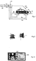
- the vehicle 100 additionally has an input device 80, an adjustment or control device (Multicomputer) 60 for the headlight system 70, a vibration sensor 10 and an inclination angle sensor 20.
- the control device 60 serves to control or regulate the light range of the headlight system 70 and is connected to the input device 80, the vibration sensor 10, the inclination angle sensor 20 and the front headlight system 70.
- the control device 60 continuously receives speed data Dv from a speed sensor 40 (i.e. via a speed sensor, the tachometer, the drive device, a separate measuring device or the like).
- Data Dl which indicate the current steering angle, is received by the control device via a steering angle sensor 30, which is located on the steering linkage itself or at a suitable location, for example at B. can be attached to a wheel.
- the control device determines from fixed, preset data Df with regard to the vehicle characteristics and type and tires, on which the braking distance is dependent, together with data Ds about the road conditions and Dw about the weather conditions, which are entered by the driver via the input direction 80 60 depending on the information Dv from the sensor 40, the optimal value for the setting of the reflectors and / or the lamps 70 of the headlight system.
- the "horizontal position" of the headlights is set as a function of the steering angle via the signal D1 of the steering angle transmitter 30.
- the angle of inclination sensor 20 serves to determine the angle of inclination of the longitudinal axis of the vehicle (horizontal axis) against the roadway in order to be able to make the initial adjustment of the headlight system 70, as will be described later.
- the angle of inclination sensor should not determine the angle of inclination against the plumb bob, since an incorrect value would be determined if parking on a slope, but rather the inclination of the horizontal axis of the motor vehicle against the road.
- the setting device 60 acts on the reflectors.
- An example of a reflector is shown in FIG. 2.
- Fig. 2 shows the left side in top view of the reflector R, which is pivotally mounted on an axis 1-2 in the vertical direction.
- the right side of FIG. 2 shows the reflector R in a side view.
- the reflector basically has a conventional structure, but a drive V is provided for pivoting in the vertical direction.
- the lighting system preferably consists of at least two reflectors which are arranged on the right or left side of the vehicle; accordingly, only one reflector is provided for a motorcycle.
- the reflector drive V can be mechanical, fluid operated, i.e. be designed pneumatically, hydraulically or electrohydraulically, or electrically operated, but the mechanical variant is less recommendable.
- the horizontal drive is not shown, but can be designed accordingly.
- the horizontal drive is coupled to the steering wheel, either directly or via the steering angle sensor 30, so that it is completely synchronized with the steering wheel movement.
- Fig. 3 shows schematically the setting options for a single reflector or lamp.
- A is a top view of a reflector and shows the horizontal adjustment positions of the reflector, namely a center position Mi (in which it is directed along the longitudinal axis of the vehicle), a maximum right position Re and a maximum left position Li that the headlights or take the reflector R depending on the angle of the steering wheel can.
- the reflector Via the drive V, the reflector can be pivoted continuously between the two extreme positions Re and Li, depending on the control by the control device. This setting is referred to below as "horizontal technology”.
- Safety margins Rr and Rl are provided to ensure a sufficient setting range even in all extreme positions.
- B and C are side views of the reflector and show the reflector R in a maximum downward inclined position Pk, in which a minimum light range is achieved, or in an upright position Pw, in which a maximum light range is achieved.
- Safety margins Rb and Ra are also provided for the required manual settings.
- the control of the position of the reflectors between the two maximum positions is carried out steplessly by the control device 60. These settings are accordingly referred to below as "vertical technology".
- the representations D and E are schematic representations of the front views of the reflector in different setting positions.
- the curves marked with reference numbers result from the following combinations: Right with Pk: circle 210 Li with Pk: circle 220 M with Pk: Ellipse 200 M with Pw: circle 230 Li with Pw: Ellipse 240 Re with Pw: Ellipse 250
- the light cone 400 of a vehicle 21 is directed towards the oncoming lane and can therefore dazzle oncoming traffic.
- the light cone 400 of the vehicle 11 illuminates the area lying next to the roadway.
- the use of horizontal technology changes the light cone in accordance with the steering angle, so that, according to the invention, the light cone 300, 300 result for the vehicles and the roadway is optimally illuminated without dazzling oncoming traffic.
- the driver enters information into the system via the operating unit 80, namely a) about the road condition (dry, wet, snowy, icy), b) about the visibility (I: good, II: medium as in the case of rain or haze) , III: bad as in fog or heavy snow).
- This information is stored as data Ds and Dw in the control unit.
- the control device determines in an auxiliary routine I whether the (stationary) vehicle has come to rest (the passengers have sat down, the load is in its place). If so, determine the control device in the auxiliary routine I sets the angle of inclination of the vehicle against the road and sets a starting position (this is a predetermined minimum lighting range) for the vertical technology. This completes the initialization of the automatic lighting system in auxiliary routine I.
- the control device continuously determines in a universal routine I from the fixed data Df about the vehicle, the entered data Ds, Dw about the road and visibility conditions and the data Dv from the speed sensor, the currently required minimum light range according to the stopping distance and sets this over the Vertical technology starting from the starting position or from the last available position.
- the lighting direction is set using the horizontal technique.
- the minimum lighting range L is continuously and continuously increased (vertical arrow) and down (arrow -) using the vertical technology (V), and the lighting direction is changed using the horizontal technology (H) between the two maximum positions Re and Li according to Head angle set.
- the angle of inclination is continuously monitored in accordance with the auxiliary routine I. If the auxiliary routine detects a change in the angle of inclination, e.g. B. in the event of sudden braking or acceleration, the auxiliary routine adjusts the position of the reflectors according to the changed angle of inclination.
- a lighting system with two lamps or reflectors per side of the vehicle is preferably used (system 2 + 2).
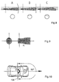
- FIG. 6 shows a top view of a combined headlight with a main reflector H (without lamp) and a fog reflector N (without lamp).
- the two reflectors are arranged on horizontal vertical swiveling axes 1-2 1'-2 'and are adjusted independently of each other with regard to the lighting range.
- a clearance A is provided between the reflectors H and N so that the reflectors cannot collide.
- lamps or reflectors
- the lamps or reflectors in a different way, for example vertically one below the other.
- the individual reflector applies accordingly, so that a further description is omitted here.
- the main and fog reflectors are used in accordance with the previously mentioned visibility conditions, and only the main reflectors at level I (good visibility).
- stage II the main reflectors are switched on, but are left in their starting position, and only the fog reflectors are operated in vertical technology.
- stage III poor visibility
- both the main and the fog reflectors are operated in the manner according to the invention.
- Fig. 7 shows schematically the change in the luminous width.
- FIG. 8 shows the dependence of the shape of this end line on the shape of the reflector for three different cases: A rounded, B straight, C graded (asymmetrical). In particular in the case of asymmetry, care must be taken that only one's own lane is illuminated, because otherwise glare could occur due to the vertical adjustment.
- reflectors in elongated form are preferably used which significantly improve the illumination of the area in front of the vehicle; such a reflector is shown in FIG. 9, for example.
- FIG. 10 schematically shows a vehicle equipped with a light sensor 110, the light sensor being arranged in two different positions A, B.
- the light sensor is designed so that it is essentially only sensitive to 180 ° of light coming from the direction of travel and is protected from light from the following vehicles.
- the mounting on the roof of the vehicle (position A) shown in FIG. 10 is preferable to position B in the front area of the vehicle.
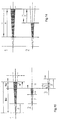
- the minimum headlight range is strictly dependent on the current stopping distance. For practical reasons, however, it has proven useful to proceed as follows. At a speed of around 50 km / h, there is a minimum lighting range of around 30 m for almost all vehicles. This lighting range is fixed as the aforementioned minimum lighting range Mi in the initial position (initialization) and is maintained (PART 1) until the determined stopping distance results in a larger required minimum lighting range (PART 2).
- the vehicle When the vehicle is stationary (initialization) and up to a speed of about 50 km / h, the vehicle has a fixed headlight range up to line F; at higher speeds, the light range becomes variable and exceeds this line accordingly.
- the control is divided into two sections, namely a first section in which the light range is kept constant and a second section in which the light range is set to the stopping distance.
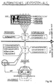
- Fig. 12 shows schematically the structure of the overall system with the components described so far.
- the heart of the system is a multicomputer 300, in which the operating unit 80 and the control device 60 are combined and which receives the previously described data Dv, Dl and Da. Permanently stored, for example in a ROM, the multicomputer contains the vehicle-specific data for calculating the braking distance.
- the road and view-specific data Ds and Dw are entered via a keyboard 310.
- the road conditions are divided into four possible categories, namely dry, wet, covered with snow and covered with ice. Each of these states is assigned a separate column on the control panel.
- the rows of the control panel are assigned to the different visibility conditions, namely good I, medium II bad III, so that there are 12 different combinations for determining the stopping distance, which all differ and lead to completely different requirements for the minimum lighting range and intensity.
- the vehicle always has the necessary lighting range and luminosity at all times and always offers road users optimum safety.
- a sensor device is provided on the vehicle that automatically determines whether the road is dry, wet, snow-covered or icy.
- the control panel can then be simplified as shown in FIG. 13.
- the driver is informed of the state of the road as a symbol or in writing via a display 320, and he only has to enter the information about the visibility.
- an interchangeable module 330 is provided, in which the vehicle-specific data are stored and can be called up by the multicoputer. If changes are made to the vehicle (e.g. Tires), only the module has to be modified or replaced; The same applies if the automatic lighting system is installed in another vehicle. For control purposes, the most important vehicle data for the driver are attached to the outside of the module.
- the control system constantly controls the headlight range to approximately the stopping distance, and because of the control of the luminosity and width, glare to other road users cannot actually occur; however, it makes sense to provide the option of temporarily reducing the headlight range, for example in the case of oncoming traffic.
- a universal routine II is provided, which can be operated using control elements 350, e.g. B. buttons on the steering wheel 340 (Fig. 12) is triggered. After the actuation of an operating element (-) according to FIG. 15, the control device steadily reduces the light range up to the above-mentioned minimum value M, so that possible dazzling of oncoming traffic is avoided.
- the control should take place in such a way that the light range is reduced at the slowest possible rate and increased at the highest possible rate. In this way, the illuminated area is kept as large as possible on average even when the headlight range is reduced.
- the stopping distance is schematically divided into the braking distance Bw and the reaction distance Rw (illustration 1).
- an emergency signal is emitted which triggers the execution of a universal routine III, in which the control device automatically reduces the headlight range to the braking distance currently required (illustration 2) until the initial value the headlight range is reached and the vehicle is stationary (illustration 3).
- the control device automatically reduces the headlight range to the braking distance currently required (illustration 2) until the initial value the headlight range is reached and the vehicle is stationary (illustration 3).
- This does not unnecessarily blind people or wild animals, for example.
- the operator receives information about the remaining braking distance at least during the beginning of the braking process.
- the emergency regulation occurs when the brakes are applied hard.
- the emergency signal can therefore be generated, for example, by a device which monitors the brake system (pedal, brake line) or by an acceleration sensor; it is also possible to generate the emergency signal in the control device itself by converting the speed signal into an acceleration value by differentiation and comparing this value with a predetermined value which corresponds to full braking.
- the headlight range is not changed in the event of emergency braking, so it remains constant at the value of the stopping distance shortly before the brake is actuated. Because of this, a very wide area is illuminated during the braking process, which offers a better overview, but with the Disadvantages of dazzling other people or animals described above.
- the third variant is to keep the headlight range fixed in relation to the road in the event of emergency braking, i.e. the light range is controlled so that the most distant, still illuminated point is fixed and the light range is then reduced as the vehicle approaches this point until the minimum light range is reached.
- This procedure means that other road users or animals are less blinded than in the second variant, so that this variant is preferable to the second variant.
- the emergency control initially shown in which the headlight range is set to the braking distance in the event of emergency braking, appears to the inventor as the most sensible option, since the headlight range obtained in this case is sufficient for each case and other road users are least impaired.
- the system according to the invention permanently and continuously indicates to the driver at what distance he can stop. This creates a significant security element; none of the known lighting systems offers such a possibility.
- an auxiliary routine II is provided according to the invention which implements a switchover between the 12 stages of the ALS. For example, it may happen while driving that the basic level (according to FIG. 12) has to be changed, for example when switching from "good view, I" to "medium II".
- the control panel must be illuminated with only the Main headlights are switched to lighting with the fog lights, and this is done with the help routine II mentioned.
- the fog reflectors are switched on and set to the value specified by the stopping distance. Accordingly, the main headlights are set to the initial value Mi and then switched off.
- auxiliary routine I sets the starting position of the headlights, based on the values of the inclination angle sensor, as soon as the vibration sensor indicates that the vehicle has come to rest.
- the universal control I then runs, which adapts the lighting range to the stopping distance starting from the initial headlight range (see FIG. 14), depending on the angle of inclination, if necessary, via the auxiliary routine I.
- This universal routine runs during the entire journey, with the following Exceptions:
- the driver can “dazzle”, that is to say reduce the headlight range arbitrarily to the minimum value, the reduction being as slow as possible and the increase (corresponding to the “fading in”) taking place as quickly as possible.
- the driver can “dazzle”, that is to say reduce the headlight range arbitrarily to the minimum value, the reduction being as slow as possible and the increase (corresponding to the “fading in”) taking place as quickly as possible.
- the driver can “dazzle”, that is to say reduce the headlight range arbitrarily to the minimum value, the reduction being as slow as possible and the increase (corresponding to the “fading in”) taking place as quickly as possible.
- the lighting width is reduced to such an extent that oncoming traffic is not disturbed by the lighting.
- the emergency control (universal routine III), namely, alternatively, the emergency control 1, in which the headlight range is set to the braking distance, the emergency control 2, in which the headlight range is kept constant at the value of the stopping distance before braking, or the emergency control 3, in which the lighting range is fixed on a line which is defined by the end of the stopping distance on the road just before the emergency braking.
- the auxiliary routine II shown above is used, which adjusts the main and fog lights according to the selected level.
- the ALS according to the invention does not require asymmetrical light to be present.
- the width of the light can also be shaped as desired using the illumination angle of the reflectors. This means that you can easily get a larger or smaller security add-on from either side.
- the light width is adapted to the respective width of the road category (e.g. country road, two-lane), so that one's own roadway is always optimally illuminated and oncoming traffic is not dazzled.
- the fixed part of 30m is also intended for all lighting constructions of the other ALS basic levels as "Dry I". In these cases, the fixed headlight range of 30m is exceeded at a lower driving speed than 50km / h.
- the automatic lighting system which is shown again overall in FIG. 16, is a multi-function system (programs and information) in which fixed programs with fixed data about the vehicle type, with adjustable information about the road conditions and visibility and with current data about the Speed form a system for controlling the light range and the luminosity of the vehicle. Settings are made at the start of the journey (auxiliary routine I), based on the inclination angle (Exrainformation I) and the outside light (Exrainformation II). During the ride, the lighting range and intensity are controlled by 3 universal routines and 2 auxiliary routines, depending on extra information and the universal information speed.
- This multifunctional system (programs and information) is the only feasible way to safely control the lighting width and intensity during every moment of the journey.
Landscapes
- Engineering & Computer Science (AREA)
- Mechanical Engineering (AREA)
- Lighting Device Outwards From Vehicle And Optical Signal (AREA)
- Non-Portable Lighting Devices Or Systems Thereof (AREA)
Applications Claiming Priority (2)
| Application Number | Priority Date | Filing Date | Title |
|---|---|---|---|
| DE4431332 | 1994-09-02 | ||
| DE4431332A DE4431332A1 (de) | 1994-09-02 | 1994-09-02 | Automatisches Lichtsystem für Kraftfahrzeuge aller Art sowie ein Verfahren zur Steuerung eines Lichtsystems |
Publications (3)
| Publication Number | Publication Date |
|---|---|
| EP0699559A2 true EP0699559A2 (fr) | 1996-03-06 |
| EP0699559A3 EP0699559A3 (fr) | 1996-07-31 |
| EP0699559B1 EP0699559B1 (fr) | 1998-08-05 |
Family
ID=6527290
Family Applications (1)
| Application Number | Title | Priority Date | Filing Date |
|---|---|---|---|
| EP95113789A Expired - Lifetime EP0699559B1 (fr) | 1994-09-02 | 1995-09-01 | Système de contrÔle automatique de l'éclairage pour véhicule |
Country Status (9)
| Country | Link |
|---|---|
| US (1) | US5798911A (fr) |
| EP (1) | EP0699559B1 (fr) |
| JP (1) | JP2786833B2 (fr) |
| KR (1) | KR960010373A (fr) |
| AT (1) | ATE169274T1 (fr) |
| AU (1) | AU3038095A (fr) |
| CA (1) | CA2157133A1 (fr) |
| DE (2) | DE4431332A1 (fr) |
| ES (1) | ES2122414T3 (fr) |
Cited By (11)
| Publication number | Priority date | Publication date | Assignee | Title |
|---|---|---|---|---|
| GB2309773A (en) * | 1996-02-01 | 1997-08-06 | Koito Mfg Co Ltd | Controlling direction of vehicle lights |
| GB2309774A (en) * | 1996-02-01 | 1997-08-06 | Koito Mfg Co Ltd | Controlling direction of vehicle lights |
| EP0823351A3 (fr) * | 1996-08-09 | 1998-08-12 | Bayerische Motoren Werke Aktiengesellschaft, Patentabteilung AJ-3 | Procédé de commande de la portée des phares en fonction de la charge du véhicule |
| FR2836103A1 (fr) * | 2002-02-18 | 2003-08-22 | Bosch Gmbh Robert | Installation pour eviter les accidents d'un vehicule avec du gibier |
| EP1520749A3 (fr) * | 1998-09-18 | 2007-06-13 | Gentex Corporation | Système commander un phare de véhicule |
| WO2008014867A1 (fr) * | 2006-08-02 | 2008-02-07 | Gm Global Technology Operations, Inc. | Phare de véhicule automobile |
| DE102009056853A1 (de) * | 2009-12-03 | 2011-06-09 | GM Global Technology Operations LLC, ( n. d. Ges. d. Staates Delaware ), Detroit | Scheinwerfer für ein Fahrzeug |
| FR2967625A1 (fr) * | 2010-11-22 | 2012-05-25 | Peugeot Citroen Automobiles Sa | Vehicule comprenant une source lumineuse de projection d'une information sur le sol devant le vehicule |
| EP2252480B1 (fr) * | 2008-03-12 | 2013-08-07 | Toyota Jidosha Kabushiki Kaisha | Dispositif et procédé d'éclairage de véhicule |
| DE102013218633A1 (de) | 2013-09-17 | 2015-03-19 | Volkswagen Aktiengesellschaft | Verfahren zum Betreiben wenigstens einer Beleuchtungsvorrichtung eines Kraftfahrzeugs |
| US10532786B1 (en) | 2018-08-28 | 2020-01-14 | The Swatch Group Research And Development Ltd | Portable active lighting device or same installed on a bicycle |
Families Citing this family (36)
| Publication number | Priority date | Publication date | Assignee | Title |
|---|---|---|---|---|
| DE4431332A1 (de) * | 1994-09-02 | 1996-05-02 | Josic Ante | Automatisches Lichtsystem für Kraftfahrzeuge aller Art sowie ein Verfahren zur Steuerung eines Lichtsystems |
| FR2760069B1 (fr) * | 1997-02-21 | 1999-05-14 | Valeo Vision | Systeme d'eclairage a projecteurs de faisceau proche de type code et de faisceau complementaire de virage |
| FR2760705B1 (fr) * | 1997-03-13 | 1999-05-28 | Valeo Vision | Systeme d'eclairage de vehicule automobile comportant au moins deux projecteurs a fonction virage |
| DE19738765B4 (de) * | 1997-09-04 | 2008-11-27 | Bayerische Motoren Werke Aktiengesellschaft | Vorrichtung zur Anzeige der momentanen Fahrtrichtung eines Fahrzeugs |
| US6067031A (en) * | 1997-12-18 | 2000-05-23 | Trimble Navigation Limited | Dynamic monitoring of vehicle separation |
| DE19845332A1 (de) * | 1998-10-01 | 2000-04-13 | Kai Winkler | Visuelle Bremsweg- und Breitenanzeige bei Fahrzeugen |
| HRP990059A2 (en) * | 1999-02-22 | 2001-08-31 | Josić Ante | Automatic and semi-automatic low/high beam regulation and high/low beam regulation for the existing light system in motor vehicles of all types and kinds (abbr. abr/sbr) |
| TW493054B (en) * | 1999-06-25 | 2002-07-01 | Koninkl Philips Electronics Nv | Vehicle headlamp and a vehicle |
| KR100509581B1 (ko) * | 2002-03-06 | 2005-08-23 | 에스엘 주식회사 | 조명패턴 자동 변환기능을 갖는 차량용 지능형 전방조명시스템 |
| US8045760B2 (en) * | 2003-02-21 | 2011-10-25 | Gentex Corporation | Automatic vehicle exterior light control systems |
| FR2868164B1 (fr) * | 2004-03-26 | 2006-06-16 | Valeo Vision Sa | Procede de detection d'une route mouillee et systeme d'eclairage mettant en oeuvre ce procede |
| DE102004016713B4 (de) * | 2004-04-05 | 2015-09-24 | Volkswagen Ag | Verfahren und System zum Steuern eines Fahrzeugscheinwerfers |
| DE102005033841A1 (de) * | 2005-04-22 | 2006-12-21 | Daimlerchrysler Ag | Scheinwerferanlage für ein Fahrzeug |
| CZ302547B6 (cs) * | 2005-07-04 | 2011-07-07 | Visteon Global Technologies, Inc. | Systém adaptivního predního osvetlení motorových vozidel |
| JP5422385B2 (ja) * | 2006-09-21 | 2014-02-19 | コーニンクレッカ フィリップス エヌ ヴェ | 車両ランプ、車両ランプを調節する方法、及び、車両ランプを備える車両 |
| DE102007053399A1 (de) * | 2007-11-09 | 2009-05-14 | Continental Automotive Gmbh | Scheinwerfer mit adaptierbarer Lichtführung |
| JP2009214812A (ja) * | 2008-03-12 | 2009-09-24 | Koito Mfg Co Ltd | 車両用前照灯装置およびその制御方法 |
| JP4675395B2 (ja) * | 2008-05-19 | 2011-04-20 | 三菱電機株式会社 | 車両用警報装置 |
| JP5787649B2 (ja) * | 2010-10-26 | 2015-09-30 | 株式会社小糸製作所 | 車両用灯具の制御装置および車両用灯具システム |
| DE102012112478B4 (de) * | 2012-12-18 | 2026-02-19 | Dr. Ing. H.C. F. Porsche Aktiengesellschaft | Verfahren zum Ermitteln einer Leuchtweite eines Scheinwerfers |
| CN103101475B (zh) * | 2013-01-25 | 2014-10-15 | 深圳市保千里电子有限公司 | 基于汽车照明系统视角与车速同步变化的控制方法及系统 |
| WO2014119981A1 (fr) * | 2013-01-30 | 2014-08-07 | Terán Balaguer Luis Fausto | Système et procédé de commande inertielle de phares automobiles |
| CN104228665B (zh) * | 2014-09-17 | 2016-08-24 | 南京航空航天大学 | 一种自适应汽车前照灯的控制方法 |
| JP2016068792A (ja) * | 2014-09-30 | 2016-05-09 | 富士重工業株式会社 | 車両用前照灯装置 |
| CN104590095B (zh) * | 2015-01-06 | 2016-09-14 | 浙江工业大学 | 一种大型车辆行驶过程中危险区域的警示方法及警示灯系统 |
| CN104742794A (zh) * | 2015-03-30 | 2015-07-01 | 无锡市崇安区科技创业服务中心 | 一种基于速度感应的汽车前照灯调整照射方向的方法 |
| KR101832967B1 (ko) * | 2016-05-16 | 2018-02-28 | 엘지전자 주식회사 | 차량에 구비된 제어장치 및 이의 제어방법 |
| CN108569189B (zh) * | 2017-03-27 | 2023-05-05 | 常州星宇车灯股份有限公司 | 一种基于图像处理的车灯反射镜调整装置及方法 |
| JP6980486B2 (ja) * | 2017-10-24 | 2021-12-15 | 株式会社小糸製作所 | 車両用灯具の制御装置及び車両用灯具システム |
| CN108515902A (zh) * | 2018-03-12 | 2018-09-11 | 中国重汽集团济南动力有限公司 | 一种基于can报文的智能大灯控制系统及方法 |
| EP3616989A1 (fr) * | 2018-08-28 | 2020-03-04 | The Swatch Group Research and Development Ltd | Dispositif d'éclairage actif portable ou placé sur un véhicule |
| DE102018131528A1 (de) * | 2018-12-10 | 2020-06-10 | Bayerische Motoren Werke Aktiengesellschaft | Bereitstellung eines optischen Bremssignals eines Kraftfahrzeugs |
| US11136744B2 (en) * | 2019-10-31 | 2021-10-05 | Deere & Company | Vehicles with control systems to perform various functions based on payload weight and methods of operating the same |
| JP2022052142A (ja) * | 2020-09-23 | 2022-04-04 | スタンレー電気株式会社 | 車両用前照灯システム、車両用前照灯システムの制御方法 |
| CN113335179A (zh) * | 2021-07-05 | 2021-09-03 | 河南理工大学 | 一种夜间远光灯自动控制装置及方法 |
| CN114189965B (zh) * | 2021-11-24 | 2023-06-02 | 重庆长安汽车股份有限公司 | 一种确定汽车前部照明灯具道路照明范围的方法 |
Citations (4)
| Publication number | Priority date | Publication date | Assignee | Title |
|---|---|---|---|---|
| DE2437585A1 (de) | 1974-05-17 | 1975-11-27 | Ko An Inc | Einrichtung bei einem kraftfahrzeug |
| DE3545495A1 (de) | 1985-12-20 | 1987-07-02 | Herbert Kripp | Frontseitige beleuchtungsanlage eines kraftfahrzeugs |
| DE3545459A1 (de) | 1985-12-20 | 1987-07-02 | Bayer Ag | Verfahren zum faerben und bedrucken von polyesterfasermaterialien |
| DE3834764A1 (de) | 1987-10-13 | 1989-05-03 | Honda Motor Co Ltd | Scheinwerfereinrichtung fuer motorraeder |
Family Cites Families (18)
| Publication number | Priority date | Publication date | Assignee | Title |
|---|---|---|---|---|
| US3179845A (en) * | 1961-05-01 | 1965-04-20 | Kulwiec Chester | Headlight illumination and signaling system for motor vehicles |
| DE2149267C3 (de) * | 1971-10-02 | 1981-05-21 | Daimler-Benz Ag, 7000 Stuttgart | Pneumatisch arbeitende Regelvorrichtung zur selbsttätigen Ausrichtung von Kraftfahrzeugscheinwerfern |
| DE2357960A1 (de) * | 1973-11-21 | 1975-07-03 | Daimler Benz Ag | Beseitigung der asymmetrie des scheinwerferlichtes beim fahren auf schnellstrassen |
| DE3110094A1 (de) * | 1981-03-16 | 1982-09-30 | Itt Ind Gmbh Deutsche | "einrichtung zur automatischen scheinwerfereinstellung bei kraftfahrzeugen" |
| US4891559A (en) * | 1985-06-13 | 1990-01-02 | Nippondenso Soken, Inc. | Apparatus for controlling a headlight of a vehicle |
| DE3601388A1 (de) * | 1986-01-18 | 1987-07-23 | Bosch Gmbh Robert | Scheinwerferanlage fuer fahrzeuge, insbesondere fuer kraftfahrzeuge |
| KR880002698A (ko) * | 1986-08-28 | 1988-05-10 | 김태용 | 자동차 회전 헤드라이트 |
| JPH0825417B2 (ja) * | 1987-08-17 | 1996-03-13 | 株式会社小糸製作所 | 二輪車輌用前照灯の照射角修正装置 |
| DE3810840C1 (fr) * | 1988-03-30 | 1989-11-09 | Messerschmitt-Boelkow-Blohm Gmbh, 8012 Ottobrunn, De | |
| JPH01278848A (ja) * | 1988-05-02 | 1989-11-09 | Nissan Motor Co Ltd | 車両用前照灯装置 |
| DE4024913A1 (de) * | 1990-08-06 | 1992-02-13 | Hella Kg Hueck & Co | Verfahren und einrichtung zur regelung der leuchtweite eines kraftfahrzeugs |
| EP0473978B1 (fr) * | 1990-08-15 | 1994-11-02 | Honda Giken Kogyo Kabushiki Kaisha | Moyen de commande pour véhicules à deux roues |
| DE4122531C2 (de) * | 1991-07-08 | 2001-06-07 | Bosch Gmbh Robert | Einrichtung zur Regelung der Leuchtweite von Scheinwerfern von Kraftfahrzeugen |
| DE4225370B4 (de) * | 1992-07-31 | 2004-02-05 | Robert Bosch Gmbh | Nebelscheinwerfer für Fahrzeuge |
| JP2633169B2 (ja) * | 1992-11-19 | 1997-07-23 | 株式会社小糸製作所 | 車輌用コーナリングランプシステム |
| US5426571A (en) * | 1993-03-11 | 1995-06-20 | Jones; Jerry | Motorcycle headlight aiming device |
| DE4341409C2 (de) * | 1993-12-04 | 2002-07-11 | Bosch Gmbh Robert | Einrichtung zur Regelung der Leuchtweite von Scheinwerfern von Kraftfahrzeugen |
| DE4431332A1 (de) * | 1994-09-02 | 1996-05-02 | Josic Ante | Automatisches Lichtsystem für Kraftfahrzeuge aller Art sowie ein Verfahren zur Steuerung eines Lichtsystems |
-
1994
- 1994-09-02 DE DE4431332A patent/DE4431332A1/de not_active Withdrawn
-
1995
- 1995-08-29 CA CA002157133A patent/CA2157133A1/fr not_active Abandoned
- 1995-08-30 US US08/521,541 patent/US5798911A/en not_active Expired - Fee Related
- 1995-08-31 AU AU30380/95A patent/AU3038095A/en not_active Abandoned
- 1995-09-01 ES ES95113789T patent/ES2122414T3/es not_active Expired - Lifetime
- 1995-09-01 DE DE59503058T patent/DE59503058D1/de not_active Expired - Fee Related
- 1995-09-01 AT AT95113789T patent/ATE169274T1/de not_active IP Right Cessation
- 1995-09-01 EP EP95113789A patent/EP0699559B1/fr not_active Expired - Lifetime
- 1995-09-02 KR KR1019950029108A patent/KR960010373A/ko not_active Ceased
- 1995-09-04 JP JP7226340A patent/JP2786833B2/ja not_active Expired - Lifetime
Patent Citations (4)
| Publication number | Priority date | Publication date | Assignee | Title |
|---|---|---|---|---|
| DE2437585A1 (de) | 1974-05-17 | 1975-11-27 | Ko An Inc | Einrichtung bei einem kraftfahrzeug |
| DE3545495A1 (de) | 1985-12-20 | 1987-07-02 | Herbert Kripp | Frontseitige beleuchtungsanlage eines kraftfahrzeugs |
| DE3545459A1 (de) | 1985-12-20 | 1987-07-02 | Bayer Ag | Verfahren zum faerben und bedrucken von polyesterfasermaterialien |
| DE3834764A1 (de) | 1987-10-13 | 1989-05-03 | Honda Motor Co Ltd | Scheinwerfereinrichtung fuer motorraeder |
Cited By (20)
| Publication number | Priority date | Publication date | Assignee | Title |
|---|---|---|---|---|
| GB2309774A (en) * | 1996-02-01 | 1997-08-06 | Koito Mfg Co Ltd | Controlling direction of vehicle lights |
| GB2309774B (en) * | 1996-02-01 | 1998-02-11 | Koito Mfg Co Ltd | A vehicle lamp illumination direction control device |
| GB2309773B (en) * | 1996-02-01 | 1998-02-11 | Koito Mfg Co Ltd | A vehicle lamp illumination direction control device |
| GB2309773A (en) * | 1996-02-01 | 1997-08-06 | Koito Mfg Co Ltd | Controlling direction of vehicle lights |
| EP0823351A3 (fr) * | 1996-08-09 | 1998-08-12 | Bayerische Motoren Werke Aktiengesellschaft, Patentabteilung AJ-3 | Procédé de commande de la portée des phares en fonction de la charge du véhicule |
| US5962980A (en) * | 1996-08-09 | 1999-10-05 | Bayerische Motoren Werke Aktiengesellschaft | Method for regulating the range of the headlights of a vehicle according to the load |
| EP1520749A3 (fr) * | 1998-09-18 | 2007-06-13 | Gentex Corporation | Système commander un phare de véhicule |
| FR2836103A1 (fr) * | 2002-02-18 | 2003-08-22 | Bosch Gmbh Robert | Installation pour eviter les accidents d'un vehicule avec du gibier |
| WO2008014867A1 (fr) * | 2006-08-02 | 2008-02-07 | Gm Global Technology Operations, Inc. | Phare de véhicule automobile |
| GB2454115A (en) * | 2006-08-02 | 2009-04-29 | Gm Global Tech Operations Inc | Headlight in a motor vehicle |
| CN101500849B (zh) * | 2006-08-02 | 2012-09-19 | Gm全球科技运作股份有限公司 | 汽车中的前照灯 |
| GB2454115B (en) * | 2006-08-02 | 2011-08-24 | Gm Global Tech Operations Inc | Headlight in a motor vehicle |
| US8401741B2 (en) | 2006-08-02 | 2013-03-19 | GM Global Technology Operations LLC | Headlamp in an automobile |
| EP2252480B1 (fr) * | 2008-03-12 | 2013-08-07 | Toyota Jidosha Kabushiki Kaisha | Dispositif et procédé d'éclairage de véhicule |
| US9013058B2 (en) | 2008-03-12 | 2015-04-21 | Toyota Jidosha Kabushiki Kaisha | Vehicle lighting device and lighting method |
| DE102009056853A1 (de) * | 2009-12-03 | 2011-06-09 | GM Global Technology Operations LLC, ( n. d. Ges. d. Staates Delaware ), Detroit | Scheinwerfer für ein Fahrzeug |
| FR2967625A1 (fr) * | 2010-11-22 | 2012-05-25 | Peugeot Citroen Automobiles Sa | Vehicule comprenant une source lumineuse de projection d'une information sur le sol devant le vehicule |
| DE102013218633A1 (de) | 2013-09-17 | 2015-03-19 | Volkswagen Aktiengesellschaft | Verfahren zum Betreiben wenigstens einer Beleuchtungsvorrichtung eines Kraftfahrzeugs |
| US10532786B1 (en) | 2018-08-28 | 2020-01-14 | The Swatch Group Research And Development Ltd | Portable active lighting device or same installed on a bicycle |
| EP3617048A1 (fr) * | 2018-08-28 | 2020-03-04 | The Swatch Group Research and Development Ltd | Dispositif d'éclairage actif portable ou placé sur un véhicule |
Also Published As
| Publication number | Publication date |
|---|---|
| JP2786833B2 (ja) | 1998-08-13 |
| DE4431332A1 (de) | 1996-05-02 |
| EP0699559A3 (fr) | 1996-07-31 |
| US5798911A (en) | 1998-08-25 |
| JPH08169273A (ja) | 1996-07-02 |
| DE59503058D1 (de) | 1998-09-10 |
| AU3038095A (en) | 1996-03-14 |
| CA2157133A1 (fr) | 1996-03-03 |
| ES2122414T3 (es) | 1998-12-16 |
| KR960010373A (ko) | 1996-04-20 |
| ATE169274T1 (de) | 1998-08-15 |
| EP0699559B1 (fr) | 1998-08-05 |
Similar Documents
| Publication | Publication Date | Title |
|---|---|---|
| EP0699559B1 (fr) | Système de contrÔle automatique de l'éclairage pour véhicule | |
| DE19602622C2 (de) | Scheinwerferanordnung für ein Fahrzeug | |
| EP3931033B1 (fr) | Procédé servant à faire fonctionner un système d'information du conducteur dans un véhicule égo, et système d'information du conducteur | |
| DE19601572C2 (de) | Einrichtung zur Leuchtbereichseinstellung eines Fahrzeugscheinwerfers, insbesondere in horizontaler Richtung | |
| DE102011006580B4 (de) | Verfahren und Steuergerät zur wegabhängigen Einstellung der Leuchtweite eines Beleuchtungssystems für ein Fahrzeug | |
| DE102011006550B4 (de) | Verfahren und Steuergerät zum Einschalten eines Fernlichts eines Fahrzeugs | |
| DE10104773A1 (de) | Beleuchtungssystem für Fahrzeuge | |
| DE19549077C2 (de) | Scheinwerfer mit veränderlicher Lichtverteilung | |
| DE10007984A9 (de) | Leuchtvorrichtung für Fahrzeuge | |
| WO2020173773A1 (fr) | Procédé pour faire fonctionner un système d'information du conducteur dans un égo-véhicule et système d'information du conducteur | |
| EP1093966B1 (fr) | Procédé et dispositif de commande de la distribution de lumière d'un phare de véhicule | |
| DE19922735A1 (de) | Fahrzeugbeleuchtungssystem | |
| DE102018200025A1 (de) | Fahrzeugbeleuchtung | |
| DE102013016761A1 (de) | Verfahren zum Betrieb von Scheinwerfern eines Kraftfahrzeugs, Scheinwerfersystem sowie Kraftfahrzeug | |
| DE10007273B4 (de) | Automatische Fahrzeugscheinwerfer-Justiervorrichtung | |
| DE102004041415B4 (de) | Einrichtung zur automatischen Einstellung der Richtung der Lichtstrahlachse eines Fahrzeugscheinwerfers | |
| DE29824081U1 (de) | Vorrichtung zur Steuerung der Leuchtweite eines Fahrzeugscheinwerfers | |
| EP4177107A1 (fr) | Procédé de fourniture d'un éclairage ajusté à la visibilité | |
| DE3436391A1 (de) | Verfahren zur betaetigung der frontseitigen beleuchtungsanlage eines kraftfahrzeuges und schaltungsanordnung zur durchfuehrung des verfahrens | |
| EP2918446B1 (fr) | Système et procédé de commande d'un phare de véhicule | |
| DE102014225526B4 (de) | Verfahren und Steuergerät zum Einstellen einer Charakteristik einer Lichtaussendung zumindest eines Scheinwerfers eines Fahrzeugs | |
| DE102005033841A1 (de) | Scheinwerferanlage für ein Fahrzeug | |
| DE19922687B4 (de) | Verfahren und Vorrichtung zum automatischen Ein- oder Ausschalten der Beleuchtung eines Fahrzeugs | |
| DE10221899B4 (de) | Verfahren zum Steuern der Lichtfunktion eines Fahrzeugscheinwerfers | |
| DE3545495A1 (de) | Frontseitige beleuchtungsanlage eines kraftfahrzeugs |
Legal Events
| Date | Code | Title | Description |
|---|---|---|---|
| PUAI | Public reference made under article 153(3) epc to a published international application that has entered the european phase |
Free format text: ORIGINAL CODE: 0009012 |
|
| AK | Designated contracting states |
Kind code of ref document: A2 Designated state(s): AT BE CH DE DK ES FR GB GR IE IT LI LU MC NL PT SE |
|
| AX | Request for extension of the european patent |
Free format text: LT PAYMENT 950901;SI PAYMENT 950901 |
|
| RAX | Requested extension states of the european patent have changed |
Free format text: LT PAYMENT 950901;SI PAYMENT 950901 |
|
| PUAL | Search report despatched |
Free format text: ORIGINAL CODE: 0009013 |
|
| AK | Designated contracting states |
Kind code of ref document: A3 Designated state(s): AT BE CH DE DK ES FR GB GR IE IT LI LU MC NL PT SE |
|
| AX | Request for extension of the european patent |
Free format text: LT PAYMENT 950901;SI PAYMENT 950901 |
|
| 17P | Request for examination filed |
Effective date: 19970124 |
|
| GRAG | Despatch of communication of intention to grant |
Free format text: ORIGINAL CODE: EPIDOS AGRA |
|
| GRAG | Despatch of communication of intention to grant |
Free format text: ORIGINAL CODE: EPIDOS AGRA |
|
| GRAH | Despatch of communication of intention to grant a patent |
Free format text: ORIGINAL CODE: EPIDOS IGRA |
|
| 17Q | First examination report despatched |
Effective date: 19971219 |
|
| GRAH | Despatch of communication of intention to grant a patent |
Free format text: ORIGINAL CODE: EPIDOS IGRA |
|
| GRAA | (expected) grant |
Free format text: ORIGINAL CODE: 0009210 |
|
| AK | Designated contracting states |
Kind code of ref document: B1 Designated state(s): AT BE CH DE DK ES FR GB GR IE IT LI LU MC NL PT SE |
|
| AX | Request for extension of the european patent |
Free format text: LT PAYMENT 950901;SI PAYMENT 950901 |
|
| LTIE | Lt: invalidation of european patent or patent extension | ||
| PG25 | Lapsed in a contracting state [announced via postgrant information from national office to epo] |
Ref country code: GR Free format text: LAPSE BECAUSE OF FAILURE TO SUBMIT A TRANSLATION OF THE DESCRIPTION OR TO PAY THE FEE WITHIN THE PRESCRIBED TIME-LIMIT Effective date: 19980805 |
|
| REF | Corresponds to: |
Ref document number: 169274 Country of ref document: AT Date of ref document: 19980815 Kind code of ref document: T |
|
| REG | Reference to a national code |
Ref country code: CH Ref legal event code: EP |
|
| PG25 | Lapsed in a contracting state [announced via postgrant information from national office to epo] |
Ref country code: LU Free format text: LAPSE BECAUSE OF NON-PAYMENT OF DUE FEES Effective date: 19980901 |
|
| REF | Corresponds to: |
Ref document number: 59503058 Country of ref document: DE Date of ref document: 19980910 |
|
| GBT | Gb: translation of ep patent filed (gb section 77(6)(a)/1977) |
Effective date: 19980828 |
|
| PG25 | Lapsed in a contracting state [announced via postgrant information from national office to epo] |
Ref country code: DK Free format text: LAPSE BECAUSE OF FAILURE TO SUBMIT A TRANSLATION OF THE DESCRIPTION OR TO PAY THE FEE WITHIN THE PRESCRIBED TIME-LIMIT Effective date: 19981105 |
|
| REG | Reference to a national code |
Ref country code: ES Ref legal event code: FG2A Ref document number: 2122414 Country of ref document: ES Kind code of ref document: T3 |
|
| ET | Fr: translation filed | ||
| REG | Reference to a national code |
Ref country code: PT Ref legal event code: SC4A Free format text: AVAILABILITY OF NATIONAL TRANSLATION Effective date: 19981103 |
|
| PG25 | Lapsed in a contracting state [announced via postgrant information from national office to epo] |
Ref country code: MC Free format text: LAPSE BECAUSE OF NON-PAYMENT OF DUE FEES Effective date: 19990331 |
|
| PLBE | No opposition filed within time limit |
Free format text: ORIGINAL CODE: 0009261 |
|
| STAA | Information on the status of an ep patent application or granted ep patent |
Free format text: STATUS: NO OPPOSITION FILED WITHIN TIME LIMIT |
|
| REG | Reference to a national code |
Ref country code: IE Ref legal event code: FD4D |
|
| 26N | No opposition filed | ||
| PG25 | Lapsed in a contracting state [announced via postgrant information from national office to epo] |
Ref country code: LI Free format text: LAPSE BECAUSE OF NON-PAYMENT OF DUE FEES Effective date: 19990930 Ref country code: CH Free format text: LAPSE BECAUSE OF NON-PAYMENT OF DUE FEES Effective date: 19990930 |
|
| REG | Reference to a national code |
Ref country code: CH Ref legal event code: PL |
|
| REG | Reference to a national code |
Ref country code: GB Ref legal event code: IF02 |
|
| PGFP | Annual fee paid to national office [announced via postgrant information from national office to epo] |
Ref country code: PT Payment date: 20020830 Year of fee payment: 8 |
|
| PGFP | Annual fee paid to national office [announced via postgrant information from national office to epo] |
Ref country code: NL Payment date: 20020916 Year of fee payment: 8 Ref country code: FR Payment date: 20020916 Year of fee payment: 8 |
|
| PGFP | Annual fee paid to national office [announced via postgrant information from national office to epo] |
Ref country code: AT Payment date: 20020919 Year of fee payment: 8 |
|
| PGFP | Annual fee paid to national office [announced via postgrant information from national office to epo] |
Ref country code: SE Payment date: 20020920 Year of fee payment: 8 Ref country code: GB Payment date: 20020920 Year of fee payment: 8 Ref country code: BE Payment date: 20020920 Year of fee payment: 8 |
|
| PGFP | Annual fee paid to national office [announced via postgrant information from national office to epo] |
Ref country code: ES Payment date: 20020926 Year of fee payment: 8 |
|
| PGFP | Annual fee paid to national office [announced via postgrant information from national office to epo] |
Ref country code: DE Payment date: 20021122 Year of fee payment: 8 |
|
| PG25 | Lapsed in a contracting state [announced via postgrant information from national office to epo] |
Ref country code: GB Free format text: LAPSE BECAUSE OF NON-PAYMENT OF DUE FEES Effective date: 20030901 Ref country code: AT Free format text: LAPSE BECAUSE OF NON-PAYMENT OF DUE FEES Effective date: 20030901 |
|
| PG25 | Lapsed in a contracting state [announced via postgrant information from national office to epo] |
Ref country code: SE Free format text: LAPSE BECAUSE OF NON-PAYMENT OF DUE FEES Effective date: 20030902 Ref country code: ES Free format text: LAPSE BECAUSE OF NON-PAYMENT OF DUE FEES Effective date: 20030902 |
|
| PG25 | Lapsed in a contracting state [announced via postgrant information from national office to epo] |
Ref country code: BE Free format text: LAPSE BECAUSE OF NON-PAYMENT OF DUE FEES Effective date: 20030930 |
|
| BERE | Be: lapsed |
Owner name: *JOSIC ANTE Effective date: 20030930 |
|
| PG25 | Lapsed in a contracting state [announced via postgrant information from national office to epo] |
Ref country code: PT Free format text: LAPSE BECAUSE OF NON-PAYMENT OF DUE FEES Effective date: 20040331 |
|
| PG25 | Lapsed in a contracting state [announced via postgrant information from national office to epo] |
Ref country code: NL Free format text: LAPSE BECAUSE OF NON-PAYMENT OF DUE FEES Effective date: 20040401 Ref country code: DE Free format text: LAPSE BECAUSE OF NON-PAYMENT OF DUE FEES Effective date: 20040401 |
|
| GBPC | Gb: european patent ceased through non-payment of renewal fee | ||
| EUG | Se: european patent has lapsed | ||
| PG25 | Lapsed in a contracting state [announced via postgrant information from national office to epo] |
Ref country code: FR Free format text: LAPSE BECAUSE OF NON-PAYMENT OF DUE FEES Effective date: 20040528 |
|
| NLV4 | Nl: lapsed or anulled due to non-payment of the annual fee |
Effective date: 20040401 |
|
| REG | Reference to a national code |
Ref country code: PT Ref legal event code: MM4A Free format text: LAPSE DUE TO NON-PAYMENT OF FEES Effective date: 20040331 |
|
| REG | Reference to a national code |
Ref country code: FR Ref legal event code: ST |
|
| REG | Reference to a national code |
Ref country code: ES Ref legal event code: FD2A Effective date: 20030902 |
|
| PG25 | Lapsed in a contracting state [announced via postgrant information from national office to epo] |
Ref country code: IT Free format text: LAPSE BECAUSE OF NON-PAYMENT OF DUE FEES;WARNING: LAPSES OF ITALIAN PATENTS WITH EFFECTIVE DATE BEFORE 2007 MAY HAVE OCCURRED AT ANY TIME BEFORE 2007. THE CORRECT EFFECTIVE DATE MAY BE DIFFERENT FROM THE ONE RECORDED. Effective date: 20050901 |