EP0699801A1 - Längstransfersystem - Google Patents
Längstransfersystem Download PDFInfo
- Publication number
- EP0699801A1 EP0699801A1 EP95112578A EP95112578A EP0699801A1 EP 0699801 A1 EP0699801 A1 EP 0699801A1 EP 95112578 A EP95112578 A EP 95112578A EP 95112578 A EP95112578 A EP 95112578A EP 0699801 A1 EP0699801 A1 EP 0699801A1
- Authority
- EP
- European Patent Office
- Prior art keywords
- transfer system
- longitudinal transfer
- rail
- profile
- rail profiles
- Prior art date
- Legal status (The legal status is an assumption and is not a legal conclusion. Google has not performed a legal analysis and makes no representation as to the accuracy of the status listed.)
- Granted
Links
- 239000004020 conductor Substances 0.000 claims abstract description 43
- 238000006073 displacement reaction Methods 0.000 abstract description 2
- 230000008878 coupling Effects 0.000 abstract 3
- 238000010168 coupling process Methods 0.000 abstract 3
- 238000005859 coupling reaction Methods 0.000 abstract 3
- 238000004519 manufacturing process Methods 0.000 description 6
- 210000001503 joint Anatomy 0.000 description 3
- 238000000034 method Methods 0.000 description 3
- RYGMFSIKBFXOCR-UHFFFAOYSA-N Copper Chemical compound [Cu] RYGMFSIKBFXOCR-UHFFFAOYSA-N 0.000 description 2
- 229910052802 copper Inorganic materials 0.000 description 2
- 239000010949 copper Substances 0.000 description 2
- 239000011810 insulating material Substances 0.000 description 2
- 239000000463 material Substances 0.000 description 2
- 230000007704 transition Effects 0.000 description 2
- 230000005540 biological transmission Effects 0.000 description 1
- 230000002860 competitive effect Effects 0.000 description 1
- 230000010339 dilation Effects 0.000 description 1
- 238000003780 insertion Methods 0.000 description 1
- 230000037431 insertion Effects 0.000 description 1
- 238000009434 installation Methods 0.000 description 1
- 239000012811 non-conductive material Substances 0.000 description 1
- 238000003908 quality control method Methods 0.000 description 1
Images
Classifications
-
- E—FIXED CONSTRUCTIONS
- E01—CONSTRUCTION OF ROADS, RAILWAYS, OR BRIDGES
- E01B—PERMANENT WAY; PERMANENT-WAY TOOLS; MACHINES FOR MAKING RAILWAYS OF ALL KINDS
- E01B25/00—Tracks for special kinds of railways
- E01B25/22—Tracks for railways with the vehicle suspended from rigid supporting rails
- E01B25/24—Supporting rails; Auxiliary balancing rails; Supports or connections for rails
-
- Y—GENERAL TAGGING OF NEW TECHNOLOGICAL DEVELOPMENTS; GENERAL TAGGING OF CROSS-SECTIONAL TECHNOLOGIES SPANNING OVER SEVERAL SECTIONS OF THE IPC; TECHNICAL SUBJECTS COVERED BY FORMER USPC CROSS-REFERENCE ART COLLECTIONS [XRACs] AND DIGESTS
- Y10—TECHNICAL SUBJECTS COVERED BY FORMER USPC
- Y10T—TECHNICAL SUBJECTS COVERED BY FORMER US CLASSIFICATION
- Y10T403/00—Joints and connections
- Y10T403/55—Member ends joined by inserted section
- Y10T403/557—Expansible section
Definitions
- the invention relates to a longitudinal transfer system made of rail profiles for guiding transport carriages from one processing station to another, two adjacent rail profiles being mechanically and electrically connected to one another.
- Individual areas or processing stations in the company are linked to one another and can cooperate with one another via longitudinal transfer systems.
- a longitudinal transfer system essentially consists of individual rail tracks that are put together and on which workpieces or tools to be machined can be automatically transported from workstation to workstation on transport trolleys. Workpieces are processed in the workstations, then conveyed from production to quality control and then to assembly, for example.
- bypass systems have been developed for a longitudinal transfer system in accordance with EP-A 94102382.2.
- the bypass systems make parallel processes possible, which enable highly flexible production processes.
- the present invention has for its object to provide a connection possibility in a longitudinal transfer system, which takes into account dillation and enables a quick exchange of rail profiles.
- a connecting part or profile strip with one rail profile is non-slip and is / are connected to the other without play but only so firmly that movement of the second rail profile is possible, in particular as a result of the dillation.
- a bridge is assigned to the two current conductors of two adjacent rail profiles in such a way that the bridge acts on one current conductor with a higher pressure than the other current conductor.
- rail strands of a transfer system are mechanically and electrically connected to one another in such a way that bridging joints are bridged, that on the one hand the current conductors can continue to be supplied with power and on the other hand the rail itself has a smooth transition to the next rail profile.
- the mechanical and also the electrical connection it is ensured that a dillation of the electrical conductors or the rail profiles is still possible despite a mechanically precise connection.
- Another important advantage of the present invention is that both the mechanical and the electrical connection can be released very quickly, so that a rail track can be replaced quickly, and that a bypass can also be used quickly from the side without considerable installation effort.
- Part of the mechanical connection takes place via a connecting part, which is introduced into a groove in the rail profiles in such a way that in one rail profile this connecting part is clamped in the groove by means of two grub screws which press a gap apart via a ball.
- the fastening part is fixed in such a way that longitudinal displacement by stretching is just still possible, but the rail strands are exactly aligned and aligned with each other, so that a carriage that runs over the treads of the rail profiles does not pass through the transition Way is affected.
- the mechanical connection is made via two profile strips, which are connected via screw bolts and engage in keyways. These bolts pull the two profile strips together on the left and right of a joint between two rail profiles.
- a pressure screw is also provided on one side of the joint, which pushes the profile strips apart again, so that a rail profile between the profile strips is kept free of play but slidable.
- an electrical connection is releasably provided between two rail tracks of a transfer system.
- an insulating shoe which preferably consists of current-insulating material, is inserted into a window between two rail profile ends.
- a clamping piece is inserted into the insulating shoe, which has two threaded holes and a shaft.
- a bridge is pushed into the shaft, which presses on current conductors which are held by the clamping piece over the bridge.
- the bridge is preferably formed with two contact surfaces on both sides of a recess, so that in each case one of the two contact surfaces rests on one conductor lug. In this case, a gap is formed between the conductor lugs, which also serves as a dilation joint for the conductor.
- the bridge is eccentrically clamped against the current conductor by a grub screw passing through the clamping piece eccentrically, so that on one side the one contact surface firmly clamps the one current conductor, but on the other side the other current conductor is displaceable.
- the bridge is made of current-conducting, preferably copper-containing material, so that an optimal transmission of the current is guaranteed.
- the grub screw which presses the bridge against the current conductor, is attacked by a screw tool through an opposite window. The window is closed by a lid.
- FIG. 1 two rail profiles 1a, 1b of a longitudinal transfer system are shown, which are assembled in a butt joint.
- the profiles 1a, 1b are connected to one another via a mechanical and an electrical connection.
- each rail profile 1a, 1b has a head 2 with running surfaces for a transport carriage (not shown in more detail), to which a rectangular hollow profile 4 is connected via a neck 3.
- a longitudinal groove 5 is formed in the head 2.
- two T-slots 8.1, 8.2 and 9.1, 9.2 are formed in a left and a right side wall 6 and 7 of the hollow profile 4, in the area of which the side walls 6 and 7, however, at the end of a rail profile 1a, 1b, such as particularly shown in Figure 2, are cut like a window.
- a rail profile 1a, 1b such as particularly shown in Figure 2 are cut like a window.
- a downward-facing surface of the hollow profile 4 is designed as a dovetail 12, a keyway 13.1 and 13.2 being formed in each of the two side walls 6 and 7.
- a joint 18 between the two rail profiles 1a and 1b is bridged by a mechanical and an electrical connection.
- the mechanical connection has a connecting part 14 which is inserted into the groove 5 of both rail profiles, overlapping the joint 18.
- the essence of the connecting part 14 is that, according to FIG. 5, three blind holes 19.1, 19.2, 19.3 are provided, a ball 20 being inserted into each blind hole, which with the aid of a grub screw 21 creates a gap 22 in the bottom of the connecting part 14 by tightening the grub screw 21 apart.
- the essential idea here is that two blind holes 21 are provided on one half of the connecting part 14 and only one blind hole 21 is provided on the other half.
- the two blind holes 19.1 and 19.2 are located on one side in the rail profile 1a, the two grub screws 21 being tightened very firmly.
- the connecting part 14 is firmly connected to the profile 1a.
- the rail profile 1b which has moved in abutment is tightened only with a grub screw 21 to such an extent that a play-free but non-jamming connection between the profiles 1a, 1b and thus a movement in the longitudinal direction is possible when the joint 18 enlarged or reduced by dillation.
- a connecting plate 23 can be part of a supporting structure, for example.
- left and right profile strips 24.1 and 24.2 are provided, which are described in more detail in EP-A 90124167.9 and interact with screw bolts 25.
- the left profile strip 24.1 according to FIGS. 7-9 has two stepped bores 26.1 and 26.2 and a threaded bore 27.
- the right profile strip 24.2 according to FIGS. 10-12 has threaded bores 28.1 and 28.2 in which the screw bolt 25 can engage.
- a grub screw not shown here, is inserted, which is provided on one side with a conical tip. This cone tip engages in a cone groove 29 (FIG. 12) and thus acts on the profile strips 24.1, 24.2 with an expansion pressure.
- the grub screw and the conical groove 29 are arranged on that side of the joint 25, which is also held loosely by the connecting part 14 so that the quite long rail profiles 1 a, 1 b can expand along their longitudinal axis by appropriate expansion in the event of temperature fluctuations.
- the selected mechanical connection enables exact adjustment and detachment of the connection of the rail profiles 1a and 1b.
- an electrical connection must also be guaranteed in order to supply the longitudinal transfer system with power, in order to drive and control trolleys. Power is supplied via current conductors 17 in the snap connections 16 according to FIG. 13.
- Each snap connection 16 preferably made of insulating material, lies on the outer surface of the rail profile 1a, 1b with contact surfaces 32.
- the current conductor 17 is clipped between two further latching lugs 33.1 and 33.2, the current conductor 17 preferably being made of copper.
- the snap connections 16 are clipped laterally along the rail profiles 1a, 1b between two windows 11 into the T-slots 9.1 and 9.2 and isolate the current conductor 17 from the profiles 1a, 1b. From both sides, however, the current conductors 17 protrude into the clear width of the window 11 with flags and abut one another or likewise form a joint. This is bridged by the electrical connection.
- an insulating shoe 35 which holds clamping pieces 34, is inserted into the window 11.
- the insulating shoe 35 is preferably made of non-conductive material, such as plastic, and is clipped into the window 11, the insulating shoe 35 being divided by a web 36.
- the clamping piece 34 is provided with two threaded bores 37.1 and 37.2, the grub screw 38 (see FIG. 4) engaging in one of the two.
- the other hole is provided for an electrical connection, not shown here.
- the current conductor 17 can be supplied with current at each connection point via this bore.
- the clamping piece 34 is designed such that the current conductor is clipped into grooves 40.1 and 40.2 between two clamping rails 39.1 and 39.2.
- a shaft 41 into which a bridge 42 is inserted.
- the bridge 42 is provided with a recess 43 which delimits two contact surfaces 44.1 and 44.2 from one another. Through the contact surfaces 44.1 and 44.2, the bridge 42 bridges a gap 45 between the two current conductors 17.1 and 17.2.
- the bridge 42 On the opposite side of the contact surfaces 44, the bridge 42 has an eccentrically arranged guide bore 46, into which the grub screw 38 engages in order to pressurize the bridge 42.
- the bridge 42 is inserted into the insulating shoe 35 together with the clamping piece 34.
- the contact surface 44.1 is pressed eccentrically against the current conductor 17.1.
- the current conductor 17.2 of the rail profile 1b is only acted upon by the contact surface 44.2 with a low pressure. Clamping takes place only to the extent that the current conductor 17.2 can move along the contact surface 44.2 when expanded due to temperature differences. Therefore, the gap 45 is provided between the current conductor 17.1 and the current conductor 17.2 in order to compensate for a linear expansion due to temperature differences to be able to. This gap 45 is bridged electrically by the bridge 42 and thus the current is conducted from the current conductor 17.1 via the bridge 42 to the current conductor 17.2.
- the window 10 is closed with an end cover 47, which is fixed by means of a fastening element 48 which engages in a holding strip 49.
- the holding strip 49 is pushed into one of the two T-slots 8.1, 8.2, so that the end cover 47 disappears in the rail profile and the outer surface of the profile remains unaffected thereby.
Landscapes
- Engineering & Computer Science (AREA)
- Mechanical Engineering (AREA)
- Architecture (AREA)
- Civil Engineering (AREA)
- Structural Engineering (AREA)
- Current-Collector Devices For Electrically Propelled Vehicles (AREA)
- Multi-Process Working Machines And Systems (AREA)
- Installation Of Bus-Bars (AREA)
Abstract
Description
- Die Erfindung betrifft ein Längstransfersystem aus Schienenprofilen zum Leiten von Transportwagen von einer Bearbeitungsstation zu einer anderen, wobei zwei benachbarte Schienenprofile miteinander mechanisch und elektrisch verbunden sind.
- Durch die immer zunehmenden Anforderungen der heutigen Unternehmen im internationalen Wettbewerb müssen Qualität und Quantität aber auch vor allem die Produktivität gesteigert werden, um konkurrenzfähig bleiben zu können. D.h. die Produkte müssen kostengünstiger gefertigt bzw. montiert werden. Dementsprechend ist es erforderlich, dass die Produktionsabläufe automatisiert und miteinander verknüpft werden. Diese Verknüpfung von Fertigungsprozessen und Montageoperationen spielt eine immer grösser werdende Rolle in der modernen Fabrikation.
- Dabei werden einzelne Bereiche bzw. Bearbeitungsstationen im Unternehmen miteinander verknüpft und können über Längstransfersysteme miteinander kooperieren.
- Ein Längstransfersystem besteht im wesentlichen aus einzelnen Schienensträngen, die zusammengesetzt werden und auf denen zu bearbeitende Werkstücke oder Werkzeuge ggfs. auf Transportwagen von Arbeitsstation zu Arbeitsstation automatisch transportiert werden. In den Arbeitsstationen werden Werkstücke bearbeitet, anschliessend beispielsweise von der Fertigung zur Qualitätskontrolle und anschliessend zur Montage befördert.
- Um zeitliche Engpässe zu überwinden bzw. parallele Montagevorgänge zu ermöglichen, sind für ein Längstransfersytem beispielsweise Bypassysteme entsprechend der EP-A 94102382.2 entwickelt worden. Durch die Bypassysteme werden Parallelabläufe möglich, die hochflexible Produktionsabläufe ermöglichen.
- Bislang ist es nicht möglich, innerhalb kürzester Zeit ein Längstransfersystem auf eine andere Linie umzustellen. Nur mit erheblichem Zeitaufwand ist es möglich, beispielsweise einen Bypass in ein Längstransfersystem zu integrieren. Somit entsteht ein Ausfall der gesamten Transferlinie und blockiert alle anderen Arbeitsabläufe. Deshalb werden diese Arbeiten meistens am Wochenende vorgenommen und sind deshalb äusserst kosten- und zeitintensiv.
- Ein weiterer wesentlicher Nachteil ist, dass durch Temperaturunterschiede in den unterschiedlichen räumlich getrennten Fertigungs- und Montagehallen oder auch der Jahreszeiten eine Längsausdehnung (Dillatation) der Schienenstränge eines Längstransfersystems erfolgt. Deshalb sind zwischen den einzelnen Schienensträngen Dillatationsfugen vorgesehen, die allerdings exakt überbrückt werden müssen.
- Dabei ist auch zu beachten, dass die elektrische Einspeisung eines Längstransfersystems für entsprechende Laufwagen, die Werkzeug und Werkstücke von einer Bearbeitungsstation zur anderen befördern, über die Schiene selbst erfolgt. Den Schienen sind deshalb Stromleiter zugeordnet, die aus einem anderen Material bestehen, wie die Schiene selbst. Dadurch ergibt sich eine unterschiedliche Längsausdehnung, die an den Verbindungsstellen der einzelnen Schienenstränge ebenfalls berücksichtigt werden muss.
- Der vorliegenden Erfindung liegt die Aufgabe zugrunde, eine Verbindungsmöglichkeit in einem Längstransfersystem zu schaffen, welche einer Dillatation Rechnung trägt und einen schnellen Austausch von Schienenprofilen ermöglicht.
- Zur Lösung dieser Aufgabe führt, dass zur mechanischen Verbindung ein Verbindungsteil bzw. Profilstreifen mit einem Schienenprofil gleitfest und mit dem anderen zwar spielfrei aber nur so fest verbunden ist/sind, dass eine Bewegung des zweiten Schienenprofils insbesondere infolge der Dillatation möglich ist. Ferner führt dazu, dass den zwei Stromleitern zweier benachbarter Schienenprofile eine Brücke so zugeordnet ist, dass die Brücke den einen Stromleiter mit einem höheren Druck beaufschlagt als den anderen Stromleiter.
- Gemäss der vorliegenden Erfindung werden Schienenstränge eines Transfersystems miteinander mechanisch und elektrisch so verbunden, dass Dillatationsfugen überbrückt werden, dass einerseits die Stromleiter weiterhin mit Strom versorgt werden können und andererseits die Schiene selbst einen glatten Übergang zum nächsten Schienenprofil aufweist. Gleichzeitig wird neben der mechanischen und auch elektrischen Verbindung gewährleistet, dass eine Dillatation der elektrischen Leiter bzw. der Schienenprofile trotz einer mechanisch genauen Verbindung immer noch möglich ist.
- Ein weiterer wesentlicher Vorteil der vorliegenden Erfindung ist, dass sowohl die mechanische, als auch die elektrische Verbindung sehr schnell lösbar ist, so dass ein Schienenstrang schnell ausgewechselt werden kann, dass beispielsweise auch ein Bypass ohne erheblichen Montageaufwand schnell von der Seite her eingesetzt werden kann.
- Ein Teil der mechanischen Verbindung erfolgt über ein Verbindungsteil, welches in eine Nut in den Schienenprofilen so eingebracht ist, dass in dem einen Schienenprofil dieses Verbindungsteil mittels zweier Madenschrauben, die über eine Kugel einen Spalt auseinanderdrücken, in der Nut verklemmt ist. In dem anschliessenden Schienenprofil ist das Befestigungsteil so festgelegt, dass ein Längsverschieben durch Dehnung gerade noch möglich ist, wobei jedoch die Schienenstränge zueinander exakt fluchten und zueinander ausgerichtet sind, so dass ein Laufwagen, der über die Laufflächen der Schienenprofile fährt, durch den Übergang in keinster Weise beeinträchtigt wird.
- Ferner erfolgt die mechanische Verbindung über zwei Profilstreifen, die über Schraubenbolzen verbunden sind und in Keilnuten eingreifen. Diese Schraubenbolzen ziehen die beiden Profilstreifen links und rechts einer Fuge zwischen zwei Schienenprofilen zusammen. Neben einem Schraubenbolzen ist aber auf der einen Seite der Fuge auch eine Druckschraube vorgesehen, welche die Profilstreifen wieder auseinanderdrückt, so dass ein Schienenprofil zwischen den Profilstreifen spielfrei aber gleitbar gehalten ist.
- Gemäss der vorliegenden Erfindung ist auch daran gedacht, dass entsprechend der mechanischen Verbindung eine elektrische Verbindung lösbar zwischen zwei Schienensträngen eines Transfersystems vorgesehen ist.
- In dem vorliegenden Ausführungsbeispiel ist in ein Fenster zwischen zwei Schienenprofilenden ein Isolierschuh eingesetzt, der bevorzugt aus stromisolierendem Material besteht. In den Isolierschuh ist ein Klemmstück eingeschoben, das zwei Gewindebohrungen und einen Schacht aufweist. In den Schacht ist eine Brücke eingeschoben, welche auf Stromleiter drückt, die von dem Klemmstück über die Brücke gehalten werden. Die Brücke ist bevorzugt mit zwei Berührungsflächen beidseits einer Ausnehmung ausgebildet, so dass jeweils eine der beiden Berührungsflächen je einer Stromleiterfahne aufliegt. Dabei ist zwischen den Stromleiterfahnen ein Spalt ausgebildet, der ebenfalls als Dillatationsfuge für den Stromleiter dient. Durch eine das Klemmstück exzentrisch durchsetzende Madenschraube wird die Brücke exzentrisch gegen die Stromleiter verspannt, so dass auf der einen Seite die eine Berührungsfläche den einen Stromleiter fest eingespannt, auf der anderen Seite der andere Stromleiter aber verschiebbar ist.
- Die Brücke ist aus stromleitendem, bevorzugt aus kupferhaltigem Material hergestellt, so dass eine optimale Übertragung des Stromes gewährleistet ist. Die Madenschraube, welche die Brücke gegen die Stromleiter drückt, wird durch ein gegenüberliegendes Fenster von einem Schraubenwerkzeug angegriffen. Das Fenster wird durch einen Deckel verschlossen.
- Im Rahmen der Erfindung soll allerdings auch liegen, dass mehrere Stromleiter in mehreren Nuten isoliert in den Schienenprofilen integriert und/oder die Stromleiter auch beidseitig an den Schienenprofilen angeordnet sein können. Ferner liegt im Rahmen der Erfindung, dass die mechanische und auch die elektrische Verbindung für sich alleine Anwendung finden, wobei jedoch die Kombination beider bevorzugt wird.
- Weitere Vorteile, Merkmale und Einzelheiten der Erfindung ergeben sich aus der nachfolgenden Beschreibung bevorzugter Ausführungsbeispiele sowie anhand der Zeichnung; diese zeigt in
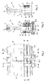
- Figur 1 eine Seitenansicht eines teilweise aufgebrochen dargestellten Ausschnittes aus einem erfindungsgemässen Längstransfersystems;
- Figur 2 einen Querschnitt durch das Längstransfersystems entlang Linie II-II in Figur 1;
- Figur 3 einen Querschnitt durch das Längstransfersystem entlang Linie III-III in Figur 1;
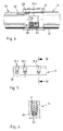
- Figur 4 einen Längsschnitt durch das Längstransfersystem entlang Linie IV-IV in Figur 1;
- Figur 5 eine Draufsicht auf ein vergrössert dargestelltes, erfindungsgemässes Verbindungsteil;
- Figur 6 einen vergrössert dargestellten Querschnitt durch das Verbindungsteil entlang Linie VI-VI in Figur 5;
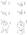
- Figur 7 eine vergrössert dargestellte Draufsicht auf einen linken Profilstreifen in Figur 2;
- Figur 8 einen Querschnitt durch den linken Profilstreifen entlang Linie VIII-VIII in Figur 7;
- Figur 9 einen Querschnitt durch den linken Profilstreifen entlang Linie IX-IX in Figur 7;
- Figur 10 eine Draufsicht auf einen rechten Profilstreifen in Figur 2;
- Figur 11 einen Querschnitt durch den rechten Profilstreifen entlang Linie XI-XI in Figur 10;
- Figur 12 einen Querschnitt durch den rechten Profilstreifen entlang Linie XII-XII in Figur 10;
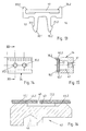
- Figur 13 eine Draufsicht auf eine erfindungsgemässe Schnappverbindung mit eingelegtem Stromleiter;
- Figur 14 eine Frontansicht eines erfindungsgemässen Klemmstückes;
- Figur 15 einen Querschnitt durch das Klemmstück entlang Linie XV-XV in Figur 14 mit eingelegtem Stromleiter;
- Figur 16 einen vergrössert dargestellten Querschnitt durch eine erfindungsgemässe Brücke mit exzentrischer Lagerung.
- Von einem Längstransfersystem sind in Figur 1 zwei Schienenprofile 1a, 1b gezeigt, die auf Stoss zusammengesetzt sind. Über eine mechanische und eine elektrische Verbindung werden die Profile 1a, 1b miteinander verbunden.
- Jedes Schienenprofil 1a, 1b weist gemäss Figur 3 einen Kopf 2 mit Laufflächen für einen nicht näher gezeigten Transportwagen auf, mit dem über einen Hals 3 ein rechteckiges Hohlprofil 4 verbunden ist. In dem Kopf 2 ist eine Längsnut 5 eingeformt.
- Sich gegenüberliegend sind in eine linke und eine rechte Seitenwand 6 bzw. 7 des Hohlprofils 4 jeweils zwei T-Nuten 8.1, 8.2 bzw. 9.1, 9.2 eingeformt, in deren Bereich die Seitenwände 6 und 7 allerdings am Ende eines Schienenprofils 1a, 1b, wie insbesondere in Figur 2 gezeigt, fensterartig eingeschnitten sind. Beim Zusammensetzen zweier Schienenprofile 1a und 1b entsteht so ein linkes und ein rechtes Fenster 10 und 11.
- Ausserhalb einer Verbindungsstelle zwischen zwei Schienenprofilen 1a und 1b ist die Nut 5 von einem Deckstreifen 15 abgedeckt. In die rechtsseitigen T-Nuten sind Schnappverbindungen 16 eingeclipst, welche Stromleiter 17 halten.
- Eine nach unten weisende Fläche des Hohlprofils 4 ist als Schwalbenschwanz 12 ausgebildet, wobei in die beiden Seitenwände 6 und 7 jeweils eine Keilnut 13.1 bzw. 13.2 eingeformt ist.
- Im Bereich einer Verbindungsstelle wird eine Fuge 18 zwischen den zwei Schienenprofilen 1a und 1b durch eine mechanische und eine elektrische Verbindung überbrückt. Die mechanische Verbindung weist ein Verbindungsteil 14 auf, welches in die Nut 5 beider Schienenprofile, die Fuge 18 übergreifend, eingesetzt ist.
- Das Wesentliche des Verbindungsteils 14 ist dabei, dass gemäss Figur 5 drei Sacklöcher 19.1, 19.2, 19.3 vorgesehen sind, wobei in jedes Sackloch eine Kugel 20 eingesetzt ist, die mit Hilfe einer Madenschraube 21 einen Spalt 22 im Boden des Verbindungsteils 14 durch Anziehen der Madenschraube 21 auseinanderdrückt.
- Der wesentliche Gedanke dabei ist, dass auf einer Hälfte des Verbindungsteils 14 zwei Sacklöcher 21 und auf der anderen Hälfte nur ein Sackloch 21 vorgesehen sind.
- Nach dem Einsetzen des Verbindungsteils 14 in die Nut 5 befinden sich auf einer Seite in dem Schienenprofil 1a die zwei Sacklöcher 19.1 und 19.2, deren beide Madenschrauben 21 sehr fest angezogen werden. Dadurch wird das Verbindungsteil 14 fest mit dem Profil 1a verbunden. Das auf Stoss herangerückte Schienenprofil 1b wird auf der anderen Seite des Verbindungsteils 14 nur mit einer Madenschraube 21 so weit angezogen, dass eine spielfreie, aber nicht klemmende Verbindung zwischen den Profilen 1a, 1b und damit eine Bewegung in Längsrichtung möglich ist, wenn sich die Fuge 18 durch Dillatation vergrössert oder verkleinert.
- Ein weiteres Teil der mechanischen Verbindung übernimmt die Festlegung der Schienenprofile 1a und 1b an einer Verbindungsplatte 23, die beispielsweise Teil eines Traggerüstes sein kann. Zum Verbinden sind ein linker und ein rechter Profilstreifen 24.1 und 24.2 vorgesehen, die in der EP-A 90124167.9 näher beschrieben sind und mit Schraubenbolzen 25 zusammenwirken.
- Dabei weist der linke Profilstreifen 24.1 gemäss den Figuren 7-9 zwei Stufenbohrungen 26.1 und 26.2 und eine Gewindebohrung 27 auf. Entsprechend symmetrisch zu den Stufenbohrungen 26.1 und 26.2 weist der rechte Profilstreifen 24.2 gemäss den Figuren 10-12 Gewindebohrungen 28.1 und 28.2 auf, in die der Schraubenbolzen 25 eingreifen kann. In die Gewindebohrung 27 des Profilstreifens 24.1 wird dagegen eine hier nicht gezeigte Madenschraube eingesetzt, die auf einer Seite mit einer Kegelspitze versehen ist. Diese Kegelspitze greift in eine Kegelnut 29 (Figur 12) ein und beaufschlagt somit die Profilstreifen 24.1, 24.2 mit einem Spreizdruck.
- Dabei ist die Madenschraube und die Kegelnut 29 auf jener Seite der Fuge 25 angeordnet, die auch durch das Verbindungsteil 14 spielfrei lose gehalten ist, damit sich durch entsprechende Dehnung bei Temperaturschwankungen die doch recht langen Schienenprofile 1a, 1b entlang ihrer Längsachse ausdehnen können.
- Durch die gewählte mechanische Verbindung wird ein exaktes Justieren und Lösen der Verbindung der Schienenprofile 1a und 1b möglich.
- Neben der mechanischen, wieder lösbaren spielfreien Verbindung muss ebenso eine elektrische Verbindung gewährleistet sein, um das Längstransfersystem mit Strom zu versorgen, um Transportwagen anzutreiben und zu steuern. Die Stromversorgung erfolgt über Stromleiter 17 in den Schnappverbindungen 16 gemäss Figur 13.
- Diese weisen Rastnasen 30 auf, über welche die Schnappverbindungen 16 in die T-Nuten 9.1 und 9.2 eingeclipst sind, wobei diese mit Anschlägen 31 hintergriffen werden. Dabei liegt jede bevorzugt aus isolierendem Material ausgebildete Schnappverbindung 16 auf der Aussenoberfläche des Schienenprofils 1a, 1b mit Auflageflächen 32 auf.
- Der Stromleiter 17 ist zwischen zwei weiteren Rastnasen 33.1 und 33.2 eingeclipst, wobei der Stromleiter 17 bevorzugt aus Kupfer besteht. Die Schnappverbindungen 16 sind seitlich entlang der Schienenprofile 1a, 1b zwischen zwei Fenster 11 in die T-Nuten 9.1 und 9.2 eingeclipst und isolieren den Stromleiter 17 von den Profilen 1a, 1b. Von beiden Seiten her ragen allerdings die Stromleiter 17 mit Fahnen in die lichte Weite des Fensters 11 ein und stossen aneinander oder bilden ebenfalls eine Fuge. Diese wird durch die elektrische Verbindung überbrückt.
- Hierzu ist in das Fenster 11 ein Isolierschuh 35 eingesetzt, welcher Klemmstücke 34 hält. Der Isolierschuh 35 ist bevorzugt aus nichtleitendem Material, wie beispielsweise Kunststoff, hergestellt und wird in das Fenster 11 eingeclipst, wobei der Isolierschuh 35 durch einen Steg 36 geteilt ist.
- Das Klemmstück 34 ist mit zwei Gewindebohrungen 37.1 und 37.2 versehen, wobei in eine von beiden die Madenschraube 38 (siehe Figur 4) eingreift. Die andere Bohrung ist für einen hier nicht gezeigten elektrischen Anschluss vorgesehen. Dabei kann über diese Bohrung der Stromleiter 17 an jeder Verbindungsstelle mit Strom versorgt werden.
- Gemäss Figur 15 ist das Klemmstück 34 so ausgebildet, dass zwischen zwei Klemmschienen 39.1 und 39.2 in Nuten 40.1 und 40.2 der Stromleiter eingeclipst wird. Unmittelbar hinter dem Stromleiter 17 befindet sich ein Schacht 41, in den eine Brücke 42 eingesetzt ist. Einerseits, den Stromleitern 17.1 und 17.2 zugewandt, ist die Brücke 42 mit einer Ausnehmung 43 versehen, die zwei Berührungsflächen 44.1 und 44.2 voneinander abgrenzt. Durch die Berührungsflächen 44.1 und 44.2 überbrückt die Brücke 42 einen Spalt 45 zwischen den beiden Stromleitern 17.1 und 17.2.
- Auf der gegenüberliegenden Seite der Berührungsflächen 44 weist die Brücke 42 eine exzentrisch angeordnete Führungsbohrung 46 auf, in die die Madenschraube 38 eingreift, um die Brücke 42 mit Druck zu beaufschlagen.
- Die Brücke 42 ist zusammen mit dem Klemmstück 34 in den Isolierschuh 35 eingesetzt. Durch Einschrauben der Madenschraube 38 wird auf der Seite des Schienenprofils 1a die Berührungsfläche 44.1 exzentrisch gegen den Stromleiter 17.1 gepresst.
- Der Stromleiter 17.2 des Schienenprofils 1b wird durch die Berührungsfläche 44.2 nur mit geringem Druck beaufschlagt. Dabei erfolgt ein Festklemmen nur soweit, dass der Stromleiter 17.2 sich bei Ausdehnung durch Temperaturunterschiede entlang der Berührungsfläche 44.2 bewegen kann. Deshalb ist zwischen dem Stromleiter 17.1 und dem Stromleiter 17.2 der Spalt 45 vorgesehen, um eine Längenausdehnung aufgrund von Temperaturunterschieden ausgleichen zu können. Dieser Spalt 45 wird elektrisch durch die Brücke 42 überbrückt und somit der Strom von dem Stromleiter 17.1 über die Brücke 42 zu dem Stromleiter 17.2 geleitet.
- Um einen Zugriff zu der Madenschraube 38 zu ermöglichen, ist in den Figuren 2 und 4 erkennbar, dass das Fenster 10 mit einem Abschlussdeckel 47 verschlossen ist, der über ein Befestigungselement 48, welches in einen Haltestreifen 49 eingreift, festgelegt ist. Dabei ist der Haltestreifen 49 in eine der beiden T-Nuten 8.1, 8.2 eingeschoben, so dass der Abschlussdeckel 47 in dem Schienenprofil verschwindet und die äussere Oberfläche des Profils davon unbeeinflusst bleibt.
Claims (14)
- Längstransfersystem aus Schienenprofilen (1a, 1b) zum Leiten von Transportwagen von einer Bearbeitungsstation zu einer anderen, wobei zwei benachbarte Schienenprofile (1a, 1b) miteinander mechanisch und elektrisch verbunden sind,
dadurch gekennzeichnet,
dass zur mechanischen Verbindung ein Verbindungsteil (14) bzw. Profilstreifen (24.1, 24.2) mit einem Schienenprofil (1a) gleitfest und mit dem anderen zwar spielfrei aber nur so fest verbunden ist/sind, dass eine Bewegung des zweiten Schienenprofils (1b) insbesondere infolge von Dillatation möglich ist. - Längstransfersystem aus Schienenprofilen (1a, 1b) zum Leiten von Transportwagen von einer Bearbeitungsstation zu einer anderen, wobei zwei benachbarte Schienenprofile (1a, 1b) miteinander mechanisch und elektrisch verbunden sind, dadurch gekennzeichnet, dass den zwei Stromleitern (17.1 und 17.2) zweier benachbarter Schienenprofile (1a, 1b) eine Brücke (42) so zugeordnet ist, dass die Brücke (42) den einen Stromleiter (17.1) mit einem höheren Druck beaufschlagt als den anderen Stromleiter (17.2).
- Längstransfersystem nach Anspruch 2, dadurch gekennzeichnet, dass die Brücke (42) mindestens eine Berührungsfläche (44.1, 44.2) beidseits einer Ausnehmung (43) aufweist, wobei eine Berührungsfläche (44.1) durch eine exzentrisch angeordnete Madenschraube (38) in einem Klemmstück (34) mit einem höheren Druck beaufschlagt wird.
- Längstransfersystem nach Anspruch 3, dadurch gekennzeichnet, dass in dem Klemmstück (34) eine Bohrung (37) zum Zuführen von Strom zu der Brücke (42) und den Stromleitern (71, 72) vorgesehen ist.
- Längstransfersystem nach Anspruch 3 oder 4, dadurch gekennzeichnet, dass das Klemmstück (34) einen Schacht (41) aufweist, in dem die Brücke (20) angeordnet ist.
- Längstransfersystem nach Anspruch 5, dadurch gekennzeichnet, dass die Stromleiter (17.1, 17.2) über dem Schacht (41) bzw. dem Klemmstück (34) in Nuten (40) von Klemmschienen (39) gehalten sind.
- Längstransfersystem nach einem der Ansprüche 3 bis 6, dadurch gekennzeichnet, dass das Klemmstück (34) in einem Isolierschuh (35) sitzt, welcher in ein Fenster (11) zwischen zwei Schienenprofile (1a, 1b) eingesetzt ist.
- Längstransfersystem nach wenigstens einem der Ansprüche 3 bis 7, dadurch gekennzeichnet, dass die Madenschraube (38) durch ein Fenster (10) in dem Schienenprofil (1a, 1b) zugänglich ist, wobei das Fenster (10) mit einerm Abschlussdeckel (47) verschliessbar ist.
- Längstransfersystem nach wenigstens einem der Ansprüche 1 bis 8, dadurch gekennzeichnet, dass in eine Längsnut (5) in den Schienenprofilen (1a und 1b) ein Verbindungsteil (14) eingesetzt ist, welches einen Spalt (22) aufweist und mit zumindest einem Sackloch (19) versehen ist, in das eine Kugel (20) eingebracht ist, wobei diese den Spalt (22) durch Anziehen einer Schraube (21) auseinanderdrückt.
- Längstransfersystem nach Anspruch 9, dadurch gekennzeichnet, dass das Verbindungsteil (14) einerseits einer Fuge (18) zwischen zwei Schienenprofilen (1a, 1b) zwei Sacklöcher (19.1 und 19.2) und andererseits ein Sackloch (19.3) aufweist, wobei die Kugel (20) in dem letztgenannten Sackloch (19.3) mit geringerem Druck beaufschlagt ist.
- Längstransfersystem nach wenigstens einem der Ansprüche 1 bis 10, dadurch gekennzeichnet, dass an den Schienenprofilen (1a, 1b) Keilnuten (13.1 und 13.2) vorgesehen sind, in die beidseitig Profilstreifen (24.1, 24.2) eingreifen und die Schienenprofile (1a, 1b) mit einer Verbindungsplatte (23) od. dgl. verbinden.
- Längstransfersystem nach Anspruch 11, dadurch gekennzeichnet, dass der eine Profilstreifen (24.1) rechts und links der Mitte zwei Stufenbohrungen (26) aufweist, wobei neben einer Bohrung noch eine Gewindebohrung (27) angeordnet ist.
- Längstransfersystem nach Anspruch 12, dadurch gekennzeichnet, dass der andere Profilstreifen (24.2) zwei Gewindebohrungen (28) rechts und links der Mitte aufweist, wobei neben einer Gewindebohrung (28) noch eine Kegelnut (29) vorgesehen ist.
- Längstransfersystem nach Anspruch 13, dadurch gekennzeichnet, dass die Profilstreifen (24.1, 24.2) durch zumindest einen Schraubenbolzen (25) mit Zug und über zumindest eine die Gewindebohrung (27) durchsetzende und sich gegen eine Kegelnut (29) abstützende Madenschraube (38) mit Druck beaufschlagt sind.
Applications Claiming Priority (2)
| Application Number | Priority Date | Filing Date | Title |
|---|---|---|---|
| DE4431064A DE4431064C2 (de) | 1994-09-01 | 1994-09-01 | Verbindung von Schienenprofilen |
| DE4431064 | 1994-09-01 |
Publications (2)
| Publication Number | Publication Date |
|---|---|
| EP0699801A1 true EP0699801A1 (de) | 1996-03-06 |
| EP0699801B1 EP0699801B1 (de) | 1998-11-04 |
Family
ID=6527108
Family Applications (1)
| Application Number | Title | Priority Date | Filing Date |
|---|---|---|---|
| EP95112578A Expired - Lifetime EP0699801B1 (de) | 1994-09-01 | 1995-08-10 | Längstransfersystem |
Country Status (3)
| Country | Link |
|---|---|
| US (1) | US5617796A (de) |
| EP (1) | EP0699801B1 (de) |
| DE (2) | DE4431064C2 (de) |
Cited By (1)
| Publication number | Priority date | Publication date | Assignee | Title |
|---|---|---|---|---|
| GB2337776A (en) * | 1998-05-06 | 1999-12-01 | Mss Clean Technology Limited | Fire resistant ceiling panel |
Families Citing this family (6)
| Publication number | Priority date | Publication date | Assignee | Title |
|---|---|---|---|---|
| JP3365210B2 (ja) * | 1996-07-11 | 2003-01-08 | 株式会社豊田自動織機 | 架設レールにおける電線配線方法及びレール部品 |
| WO1999041455A1 (en) * | 1998-02-11 | 1999-08-19 | Per Peterson | Dolly track |
| US8556189B2 (en) * | 2010-02-01 | 2013-10-15 | Xin Yu Group Co., Ltd. | Conductive rail joint |
| US20140108028A1 (en) | 2012-10-12 | 2014-04-17 | Mckesson Automation Inc. | Apparatuses, systems, and methods for anticipating and delivering medications from a central pharmacy to a patient in a healthcare facility |
| US9150119B2 (en) * | 2013-03-15 | 2015-10-06 | Aesynt Incorporated | Apparatuses, systems, and methods for anticipating and delivering medications from a central pharmacy to a patient using a track based transport system |
| KR20140126183A (ko) * | 2013-04-22 | 2014-10-30 | 최재준 | 대차 이송레일 |
Citations (6)
| Publication number | Priority date | Publication date | Assignee | Title |
|---|---|---|---|---|
| CH84567A (de) * | 1919-04-19 | 1920-03-16 | Paul Maurer | Schienenstoßverbindung |
| DE2606609B1 (de) * | 1976-02-19 | 1977-07-21 | Stromag Maschf | Dehnverbinder fuer Stromschienen |
| FR2508949A1 (fr) * | 1981-07-01 | 1983-01-07 | Tourtellier Sa Ets | Monorail |
| EP0139915A1 (de) * | 1983-08-13 | 1985-05-08 | R. Stahl Fördertechnik GmbH | Tragschienenanordnung für Hängebahnen od. dgl. |
| FR2559173A2 (fr) * | 1982-11-08 | 1985-08-09 | Bouche Marius | Systeme antibruit pour rail |
| EP0391164A1 (de) * | 1989-04-01 | 1990-10-10 | Wampfler Gmbh | Stossverbindungsvorrichtung |
Family Cites Families (12)
| Publication number | Priority date | Publication date | Assignee | Title |
|---|---|---|---|---|
| US503101A (en) * | 1893-08-08 | Benjamin c | ||
| US2498568A (en) * | 1947-05-09 | 1950-02-21 | Mary E Mosebach | Trolley wire connector |
| US2831071A (en) * | 1953-12-08 | 1958-04-15 | Ashton B Taylor | Expansion joint for electrical trolley system |
| US2933567A (en) * | 1957-10-17 | 1960-04-19 | Electric Service Works | Electric conductor system |
| GB1147187A (en) * | 1965-11-17 | 1969-04-02 | Qualter Hall & Co Sales Ltd | Monorail trackway |
| US3528608A (en) * | 1968-09-09 | 1970-09-15 | Dashaveyor Co | Expansion joint |
| US4485967A (en) * | 1982-07-19 | 1984-12-04 | Edwards Lawrence K | Mechanical joint |
| DE3910542C1 (en) * | 1989-04-01 | 1990-08-30 | R. Stahl Foerdertechnik Gmbh, 7118 Kuenzelsau, De | Rail for a monorail suspension railway |
| US5009168A (en) * | 1989-10-30 | 1991-04-23 | Gerber Garment Technology, Inc. | Track expander and method of use |
| US4967669A (en) * | 1989-10-30 | 1990-11-06 | Gerber Garment Technology, Inc. | Track expander device for a conveyorized transport system |
| DE4026737A1 (de) * | 1990-08-24 | 1992-02-27 | Montech Ag | Vorrichtung zum loesbaren verbinden zweier profile |
| DE4305347A1 (de) * | 1993-02-20 | 1994-08-25 | Montech Ag | Längstransfersystem |
-
1994
- 1994-09-01 DE DE4431064A patent/DE4431064C2/de not_active Expired - Fee Related
-
1995
- 1995-08-10 EP EP95112578A patent/EP0699801B1/de not_active Expired - Lifetime
- 1995-08-10 DE DE59504124T patent/DE59504124D1/de not_active Expired - Fee Related
- 1995-08-31 US US08/521,830 patent/US5617796A/en not_active Expired - Fee Related
Patent Citations (6)
| Publication number | Priority date | Publication date | Assignee | Title |
|---|---|---|---|---|
| CH84567A (de) * | 1919-04-19 | 1920-03-16 | Paul Maurer | Schienenstoßverbindung |
| DE2606609B1 (de) * | 1976-02-19 | 1977-07-21 | Stromag Maschf | Dehnverbinder fuer Stromschienen |
| FR2508949A1 (fr) * | 1981-07-01 | 1983-01-07 | Tourtellier Sa Ets | Monorail |
| FR2559173A2 (fr) * | 1982-11-08 | 1985-08-09 | Bouche Marius | Systeme antibruit pour rail |
| EP0139915A1 (de) * | 1983-08-13 | 1985-05-08 | R. Stahl Fördertechnik GmbH | Tragschienenanordnung für Hängebahnen od. dgl. |
| EP0391164A1 (de) * | 1989-04-01 | 1990-10-10 | Wampfler Gmbh | Stossverbindungsvorrichtung |
Cited By (1)
| Publication number | Priority date | Publication date | Assignee | Title |
|---|---|---|---|---|
| GB2337776A (en) * | 1998-05-06 | 1999-12-01 | Mss Clean Technology Limited | Fire resistant ceiling panel |
Also Published As
| Publication number | Publication date |
|---|---|
| DE59504124D1 (de) | 1998-12-10 |
| US5617796A (en) | 1997-04-08 |
| DE4431064C2 (de) | 1996-11-07 |
| EP0699801B1 (de) | 1998-11-04 |
| DE4431064A1 (de) | 1996-03-14 |
Similar Documents
| Publication | Publication Date | Title |
|---|---|---|
| DE4010840C2 (de) | Befestigungsplatte | |
| EP0136431B1 (de) | Konstruktion aus Profilstäben | |
| EP0452256A1 (de) | Eckverbindung zweier Profile mit C-förmigem Anschluss mittels eines Eckverbinders und Winkelstück zur Herstellung der Verbindung | |
| EP0092685A1 (de) | Schnellwechsel- und/oder Spannvorrichtung für die Formwerkzeuge von Spritzgiessmaschinen | |
| DE2933704A1 (de) | Druckmittelverbindung zwischen einem ventilblock und einem zumindest einen doppelt wirkenden druckmittelmotor aufweisenden verbraucher | |
| EP0922547A2 (de) | Maschine zum Bearbeiten von Fensterrahmen-Holmen | |
| AT404687B (de) | Anlage zur bearbeitung und/oder montage von bauteilen | |
| EP0699801A1 (de) | Längstransfersystem | |
| DE3910542C1 (en) | Rail for a monorail suspension railway | |
| EP0802102A1 (de) | Weichenendverschluss | |
| EP0349794B1 (de) | Vorrichtung zum Kuppeln und Entkuppeln von Greiferschienenteilen | |
| DE3900304C2 (de) | ||
| EP0154813A1 (de) | Spannvorrichtung für Werkzeugmaschinen | |
| DE4110185C1 (de) | ||
| DE3739090C2 (de) | ||
| EP0423474B1 (de) | Vorrichtung zum lösbaren Verbinden von zwei Profilstäben | |
| DE102020005960A1 (de) | Platte mit mindestens einer Nut in ihrer Oberfläche, Verfahren zur Herstellung einer Nut in der Oberfläche einer Platte und Nutenstein | |
| AT408024B (de) | Verbindungselement | |
| DE3224282A1 (de) | Linearkugellagereinheit | |
| EP0493666B1 (de) | Bearbeitungsmaschine für Hohlprofile | |
| DE4124157A1 (de) | Modulplatte, traeger o. dgl. element zur verwendung bei maschinenaufbauten | |
| EP0275867A1 (de) | Vorrichtung zur geradlinigen Bewegung von Teilen oder Gegenständen | |
| EP0903505A1 (de) | Element zum Festlengen in einem Innenraum eines Hohlprofiles od. dgl. Werkstück | |
| DE4310631C2 (de) | Vorschubeinrichtung zum Profilieren von Fenstersprossen aus Holz oder dergl. | |
| DE20002721U1 (de) | Fügevorrichtung |
Legal Events
| Date | Code | Title | Description |
|---|---|---|---|
| PUAI | Public reference made under article 153(3) epc to a published international application that has entered the european phase |
Free format text: ORIGINAL CODE: 0009012 |
|
| AK | Designated contracting states |
Kind code of ref document: A1 Designated state(s): DE FR IT |
|
| 17P | Request for examination filed |
Effective date: 19960420 |
|
| 17Q | First examination report despatched |
Effective date: 19960906 |
|
| GRAG | Despatch of communication of intention to grant |
Free format text: ORIGINAL CODE: EPIDOS AGRA |
|
| GRAG | Despatch of communication of intention to grant |
Free format text: ORIGINAL CODE: EPIDOS AGRA |
|
| GRAG | Despatch of communication of intention to grant |
Free format text: ORIGINAL CODE: EPIDOS AGRA |
|
| GRAH | Despatch of communication of intention to grant a patent |
Free format text: ORIGINAL CODE: EPIDOS IGRA |
|
| GRAH | Despatch of communication of intention to grant a patent |
Free format text: ORIGINAL CODE: EPIDOS IGRA |
|
| GRAA | (expected) grant |
Free format text: ORIGINAL CODE: 0009210 |
|
| AK | Designated contracting states |
Kind code of ref document: B1 Designated state(s): DE FR IT |
|
| REF | Corresponds to: |
Ref document number: 59504124 Country of ref document: DE Date of ref document: 19981210 |
|
| ET | Fr: translation filed | ||
| ITF | It: translation for a ep patent filed | ||
| PLBE | No opposition filed within time limit |
Free format text: ORIGINAL CODE: 0009261 |
|
| STAA | Information on the status of an ep patent application or granted ep patent |
Free format text: STATUS: NO OPPOSITION FILED WITHIN TIME LIMIT |
|
| 26N | No opposition filed | ||
| PGFP | Annual fee paid to national office [announced via postgrant information from national office to epo] |
Ref country code: FR Payment date: 20040809 Year of fee payment: 10 |
|
| PGFP | Annual fee paid to national office [announced via postgrant information from national office to epo] |
Ref country code: DE Payment date: 20041027 Year of fee payment: 10 |
|
| PG25 | Lapsed in a contracting state [announced via postgrant information from national office to epo] |
Ref country code: IT Free format text: LAPSE BECAUSE OF NON-PAYMENT OF DUE FEES;WARNING: LAPSES OF ITALIAN PATENTS WITH EFFECTIVE DATE BEFORE 2007 MAY HAVE OCCURRED AT ANY TIME BEFORE 2007. THE CORRECT EFFECTIVE DATE MAY BE DIFFERENT FROM THE ONE RECORDED. Effective date: 20050810 |
|
| PG25 | Lapsed in a contracting state [announced via postgrant information from national office to epo] |
Ref country code: DE Free format text: LAPSE BECAUSE OF NON-PAYMENT OF DUE FEES Effective date: 20060301 |
|
| PG25 | Lapsed in a contracting state [announced via postgrant information from national office to epo] |
Ref country code: FR Free format text: LAPSE BECAUSE OF NON-PAYMENT OF DUE FEES Effective date: 20060428 |
|
| REG | Reference to a national code |
Ref country code: FR Ref legal event code: ST Effective date: 20060428 |