EP0701096B1 - Verfahren zum Betreiben einer Kälteerzeugungsanlage für das Klimatisieren von Fahrzeugen und eine Kälteerzeugungsanlage zur Durchführung desselben - Google Patents
Verfahren zum Betreiben einer Kälteerzeugungsanlage für das Klimatisieren von Fahrzeugen und eine Kälteerzeugungsanlage zur Durchführung desselben Download PDFInfo
- Publication number
- EP0701096B1 EP0701096B1 EP95112257A EP95112257A EP0701096B1 EP 0701096 B1 EP0701096 B1 EP 0701096B1 EP 95112257 A EP95112257 A EP 95112257A EP 95112257 A EP95112257 A EP 95112257A EP 0701096 B1 EP0701096 B1 EP 0701096B1
- Authority
- EP
- European Patent Office
- Prior art keywords
- compressor
- refrigerant
- cooling system
- circuit
- pressure side
- Prior art date
- Legal status (The legal status is an assumption and is not a legal conclusion. Google has not performed a legal analysis and makes no representation as to the accuracy of the status listed.)
- Expired - Lifetime
Links
Images


Classifications
-
- B—PERFORMING OPERATIONS; TRANSPORTING
- B60—VEHICLES IN GENERAL
- B60H—ARRANGEMENTS OF HEATING, COOLING, VENTILATING OR OTHER AIR-TREATING DEVICES SPECIALLY ADAPTED FOR PASSENGER OR GOODS SPACES OF VEHICLES
- B60H1/00—Heating, cooling or ventilating devices
- B60H1/32—Cooling devices
- B60H1/3204—Cooling devices using compression
- B60H1/3223—Cooling devices using compression characterised by the arrangement or type of the compressor
-
- F—MECHANICAL ENGINEERING; LIGHTING; HEATING; WEAPONS; BLASTING
- F04—POSITIVE - DISPLACEMENT MACHINES FOR LIQUIDS; PUMPS FOR LIQUIDS OR ELASTIC FLUIDS
- F04B—POSITIVE-DISPLACEMENT MACHINES FOR LIQUIDS; PUMPS
- F04B27/00—Multi-cylinder pumps specially adapted for elastic fluids and characterised by number or arrangement of cylinders
- F04B27/08—Multi-cylinder pumps specially adapted for elastic fluids and characterised by number or arrangement of cylinders having cylinders coaxial with, or parallel or inclined to, main shaft axis
- F04B27/14—Control
- F04B27/16—Control of pumps with stationary cylinders
- F04B27/18—Control of pumps with stationary cylinders by varying the relative positions of a swash plate and a cylinder block
- F04B27/1804—Controlled by crankcase pressure
-
- F—MECHANICAL ENGINEERING; LIGHTING; HEATING; WEAPONS; BLASTING
- F25—REFRIGERATION OR COOLING; COMBINED HEATING AND REFRIGERATION SYSTEMS; HEAT PUMP SYSTEMS; MANUFACTURE OR STORAGE OF ICE; LIQUEFACTION SOLIDIFICATION OF GASES
- F25B—REFRIGERATION MACHINES, PLANTS OR SYSTEMS; COMBINED HEATING AND REFRIGERATION SYSTEMS; HEAT PUMP SYSTEMS
- F25B49/00—Arrangement or mounting of control or safety devices
- F25B49/02—Arrangement or mounting of control or safety devices for compression type machines, plants or systems
- F25B49/022—Compressor control arrangements
-
- F—MECHANICAL ENGINEERING; LIGHTING; HEATING; WEAPONS; BLASTING
- F25—REFRIGERATION OR COOLING; COMBINED HEATING AND REFRIGERATION SYSTEMS; HEAT PUMP SYSTEMS; MANUFACTURE OR STORAGE OF ICE; LIQUEFACTION SOLIDIFICATION OF GASES
- F25B—REFRIGERATION MACHINES, PLANTS OR SYSTEMS; COMBINED HEATING AND REFRIGERATION SYSTEMS; HEAT PUMP SYSTEMS
- F25B9/00—Compression machines, plants or systems, in which the refrigerant is air or other gas of low boiling point
- F25B9/002—Compression machines, plants or systems, in which the refrigerant is air or other gas of low boiling point characterised by the refrigerant
- F25B9/008—Compression machines, plants or systems, in which the refrigerant is air or other gas of low boiling point characterised by the refrigerant the refrigerant being carbon dioxide
-
- F—MECHANICAL ENGINEERING; LIGHTING; HEATING; WEAPONS; BLASTING
- F25—REFRIGERATION OR COOLING; COMBINED HEATING AND REFRIGERATION SYSTEMS; HEAT PUMP SYSTEMS; MANUFACTURE OR STORAGE OF ICE; LIQUEFACTION SOLIDIFICATION OF GASES
- F25B—REFRIGERATION MACHINES, PLANTS OR SYSTEMS; COMBINED HEATING AND REFRIGERATION SYSTEMS; HEAT PUMP SYSTEMS
- F25B2309/00—Gas cycle refrigeration machines
- F25B2309/06—Compression machines, plants or systems characterised by the refrigerant being carbon dioxide
- F25B2309/061—Compression machines, plants or systems characterised by the refrigerant being carbon dioxide with cycle highest pressure above the supercritical pressure
-
- F—MECHANICAL ENGINEERING; LIGHTING; HEATING; WEAPONS; BLASTING
- F25—REFRIGERATION OR COOLING; COMBINED HEATING AND REFRIGERATION SYSTEMS; HEAT PUMP SYSTEMS; MANUFACTURE OR STORAGE OF ICE; LIQUEFACTION SOLIDIFICATION OF GASES
- F25B—REFRIGERATION MACHINES, PLANTS OR SYSTEMS; COMBINED HEATING AND REFRIGERATION SYSTEMS; HEAT PUMP SYSTEMS
- F25B2600/00—Control issues
- F25B2600/17—Control issues by controlling the pressure of the condenser
-
- F—MECHANICAL ENGINEERING; LIGHTING; HEATING; WEAPONS; BLASTING
- F25—REFRIGERATION OR COOLING; COMBINED HEATING AND REFRIGERATION SYSTEMS; HEAT PUMP SYSTEMS; MANUFACTURE OR STORAGE OF ICE; LIQUEFACTION SOLIDIFICATION OF GASES
- F25B—REFRIGERATION MACHINES, PLANTS OR SYSTEMS; COMBINED HEATING AND REFRIGERATION SYSTEMS; HEAT PUMP SYSTEMS
- F25B40/00—Subcoolers, desuperheaters or superheaters
Definitions
- the invention relates to a method for operating a refrigeration system for air conditioning vehicles and a refrigeration system to perform the same according to the preamble of claim 1 with respect to the method and the preamble of claim 12 with respect to Refrigeration system.
- a generic method or a generic device is known from WO-A-93/06423 or EP 0 424 474.
- a method described for process control in a vapor compression circuit This includes a compressor, a cooler, a throttle valve and an evaporator that is successively connected in series are and form an integral, closed cycle that under supercritical pressure on the high pressure side of the circuit is working.
- Cooling capacity By varying the enthalpy difference of the Refrigerant upstream of the throttle and behind the throttle upstream of the inlet opening of the evaporator Cooling capacity can be controlled.
- the refrigerant is after the Compression as far as possible in the gas cooler from a flow around it Cooling medium cooled down, as this makes technical sense is.
- By regulating the throttle valve it turns on the High pressure side to the desired enthalpy difference to reach.
- the cooling capacity at the evaporator increases with increasing, or decreases with decreasing Pressure on the high pressure side.
- COP Coefficient of Performance
- the COP increases with the known one Pressure control however with increasing pressure on the high pressure side, i.e. with increasing cooling capacity requirement, only up to one certain amount. Then he starts to lose weight because the added cooling capacity no longer the additional Can compensate for work in compression. With very little Cooling power requirement, the throttle is turned on, whereby the enthalpy difference becomes small. This will, however the COP is also very small, i.e. it will have a high compaction performance provided and only a small amount of cooling capacity implemented, so that the known cycle process becomes extremely inefficient.
- the type of power control described thus points in terms of efficiency considerations only a limited range on, which is between a lower and an upper value of cooling capacity, between about 2 and 10 kW, moved and one consumer can be made available. However, this also applies cooling capacity is offered if there is little or no cooling demand consists. A working according to the known method Air conditioning can therefore not with regard to the cold supply can be individually adapted to the wishes of the passenger, so that the system achieves insufficient comfort and thus is unsuitable for vehicles.
- the invention has for its object a generic Method or a generic refrigeration system in this regard further develop or further develop that efficiency and the comfort of the system is increased so much that a Vehicle suitability of an air conditioning system working with this is made possible.
- the task is according to the invention with respect to the method in claim 1 and with respect to the refrigeration system characteristic features specified in claim 12 solved.
- a cycle process is made possible in which Cooling capacity under all operating conditions of the vehicle and sufficiently available for all environmental conditions can be put.
- refrigerant flows through the compressor If necessary, more or less promoted through the regulation, whereby more or less in refrigerant mass and thus in refrigeration capacity can be offered as desired on the evaporator.
- the Refrigerant transport is largely independent of the process pressure in a cycle, so that always, even at very high or low Cooling capacity requirement, in the area of maximum COP the refrigeration system can be operated. This is a control area the cooling capacity from 0 to a maximum in technical reasonable amount of achievable value with high COP, so high efficiency of the circuit in terms of its efficiency achievable, whereby a very high air conditioning comfort is achieved becomes.
- the compressor starts up when there is no need Cooling capacity at idle, when a need arises by appropriately regulating its throughput by slow continuous increase in load with regard to the conveyance of the refrigerant a gentle increase in the range of cooling services to the desired value. Because of the high comfort - No more cooling capacity is offered than requested becomes - with at the same time high efficiency or high efficiency of the cycle is therefore the use of one with a Air conditioning system equipped in such a way sensible in a vehicle and thus the vehicle suitability given.
- Fig. 1 is a vapor compression circuit, the one connected in series one after the other Compressor 2, a gas cooler 3, a throttle means 4 and one Evaporator 5 includes.
- the compressor 2 is here its throughput adjustable.
- the throttling means can also be regulated 4, which can be designed as an expansion valve.
- the compressor 2 compresses an amount of refrigerant from an outlet pressure p 1 to a higher pressure p 2 , as shown in FIG. 2 , the process temperature rising from T 1 to T 2 .
- the compressed gaseous refrigerant is now isobarically cooled in the gas cooler 3 to a temperature T 3 via a coolant flowing around it, such as cold air or water.
- the coolant is expanded to a pressure p 3 which corresponds to the outlet pressure p 1 , the coolant further cooling to a temperature T 4 which is in the liquefaction region of the refrigerant.
- the resulting two-phase gas / liquid mixture of the refrigerant reaches the evaporator 5, the liquid portion evaporates, or the very cool gas portion warms up there, releasing cold or absorbing heat from the outside.
- the initial temperature T 1 is reached again.
- the cooling capacity offered on the evaporator 5 is calculated the product of the mass flow of the coolant and the enthalpy difference between the high pressure and low pressure side 6.7 of the circuit 1.
- To meet the refrigeration demand compressor 2 is designed to be adjustable. As a result, the throughput of coolant through the compressor 2 and thus the mass flow in circuit 1 adapted to this need become.
- the opening cross section is the cross section of the refrigerant-carrying Line before or after the choke point corresponds.
- the pressure difference is large enough so that the coolant is conveyed even in the event of a change, which always occurs when the performance is adjusted to meet a new current need, under a constant pressure ratio in the circuit 1.
- Fig. 3 shows a circuit 1 of the previous embodiment alternative circuit 8.
- the circuit 8 includes in Difference to circuit 1 also a counterflow heat exchanger 9 and a buffer tank 10.
- the throttle is as Constant throttle valve 11 is formed. All additional circuit components are in the integral circle with the previous ones also connected in series.
- the high pressure part of the counterflow heat exchanger 9 is between the gas cooler 3 and the constant throttle valve 11 arranged on the high pressure side 6 of the circuit 8, while the low pressure part on low pressure side 7 between Evaporator 5 and compressor 2 is located.
- the buffer tank 10 is on the one hand with the exit of the evaporator 5 and on the other hand via its outlet 12 for gaseous refrigerant connected to the low-pressure part of the counterflow heat exchanger 9.
- the controllable compresses identically to the circuit according to FIG. 2 Compressor 2 a certain amount of refrigerant while cooling in Gas cooler 3.
- the cooled refrigerant is now through the high pressure part of the counterflow heat exchanger 9 passed, in which it isobarically cooled even further.
- By relaxing over the constant throttle valve 11 arrives at the coolant isenthalpically comparatively lower temperatures than in the example of the Circuit 1.
- a portion of the liquid evaporates at the evaporator 5 of the two-phase mixture with heat absorption. The rest of it
- the liquid portion of the refrigerant then collects in the buffer tank 10.
- the essentially gaseous fraction flows into the Low-pressure part of the counterflow heat exchanger 9 will continue there warmed up and from there reaches the compressor 2.
- the compressor 2 delivers accordingly more refrigerant. Since the throttling agent is not here is adjustable, the pressure is increased at the same time the high pressure side 6 of the circuit 8 and thus an enlargement the enthalpy difference. There will also be a relocation of Amount of coolant in the entire circuit towards the high pressure side 6. Due to the increased enthalpy difference and at the same time increased mass flow due to the increase in throughput the compressor 2 has more cooling capacity than a comparable one Funding in circuit 1 offered. Thereby is on the compressor 2 for the desired cooling capacity requirement a lower flow rate and thus a lower flow rate needed. Because of the different cooling needs pressure change on high pressure side 6 is everyone Refrigeration capacity assigned a specific circuit 8, such as Fig.
- thermodynamic Circulation-limited area becomes larger for smaller cooling capacities it shifts to lower pressures, i.e. the ones from The area limited by the thermodynamic cycle becomes smaller.
- An advantage of the circuit 8 is the elimination a complex valve control for the expansion valve, with of working at maximum COP in every area and under all driving conditions and environmental conditions would be possible.
- the buffer container 10 is due to its Storage capacity of refrigerant with a very high refrigerant accumulation on the high pressure side 6 of the circuit 8 at high Cooling power requirement a strong drop in the suction pressure prevented in the evaporator 5.
- he collects excess Refrigerant quantities from the circuit 8 with a low cooling capacity requirement, so at lower pressures on the high pressure side 6 of the circuit 8. It also compensates for the amount of leakage Refrigerant in the circuit 8.
- the counterflow heat exchanger 9 improved by the additional Cooling of the refrigerant after passing through the gas cooler 3 the available cooling capacity at the evaporator 5 and thus the efficiency the refrigeration process and thus the refrigeration system. He also serves to recirculate lubricating oil from the Compressor 2 enters circuit 8, to compressor 2.
- the flow rate control of the compressor 2 can be different Species. On the one hand about the change in its drive speed, on the other hand about changing its compression stroke as well about changing its final compression volume. Furthermore is a regulation of the intake amount of refrigerant on the intake side 13 via an adjustable suction throttle, which the compressor 2 included there, conceivable.
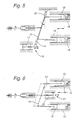
- the compressor 2 can be used as a swash plate compressor according to FIG. 5 be trained.
- To change the compression stroke points the compressor 2 at its respective lower peripheral region 14 Swashplate 15 on an adjusting device 16, which on the Principle of a displaceable adjusting piston 17 can be based.
- the Adjustment device 16 brings about a movement direction the acted upon by the swash plate 15 and in Compression cylinders 18 guided compression pistons 19 parallel Displacement of the adjusting piston 17 a radial movement of the swash plate 15, which is movably mounted on its upper peripheral region 20 is.
- the dashed version of a compression piston 19 shows the position of the compressor 2 at a minimum Compression stroke.
- FIG. 6 is the principle for changing the final compression volume of the compressor 2 shown.
- This is an adjustment device 21 used, also on a parallel to the position of the compression cylinder 18 shift an actuating piston 22 is based.
- the actuating piston 22 engages here, however centered on the swash plate 15 on the compression cylinders 18 facing page 23.
- the swash plate 15 experiences thereby an axial displacement when the actuating piston 22 is displaced, causing a shift in top dead center of the Compression piston 19 and thus a change in the final compression volume is achieved.
- the dashed version of the Compression piston 18 shows a position at a very high Final compression volume.
- compressors 2 can also be used in series connected in series or parallel to each other in the circuit be arranged instead of a compressor.
- the adjustment devices for changes in speed, intake quantity, Compression end volume and compression stroke of the compressor 2 can be operated manually using a knurled wheel inside the passenger compartment be operable depending on the need for cooling capacity, after which the circuit depending on the position set which provides the individually required cooling capacity. This The cooling capacity value is determined as far as on the adjustment nothing is changed manually.
- the compressor 2 can be driven independently of the drive motor of the vehicle with a separate motor, in particular be coupled to an electric motor.
- the electric motor draws its electrical energy from a battery or a generator, which is connected to the vehicle engine. This will make one allows flexible arrangement of the refrigeration system in the vehicle.
- the drive of the compressor 2 also directly coupled to the drive motor of the vehicle his.
- the arrangement of the refrigeration system essentially set, however, this may be due to the lack of a separate drive motor and a power generator very compact and thus designed to save space become. This is for use especially at very small motor vehicles in which the installation space is minimal, especially Cheap.
- the electricity generation and separate drive components all with these associated mechanical and electrical power losses.
- the refrigerant throughput of the compressor 2 now via the drive of the Vehicle engine depends on its speed, it makes sense to the adjustment activity of the respective adjustment device in any case from the current operating range of the vehicle engine dependent to influence excessive generation or much too low cooling capacity due to too high or too to prevent low refrigerant throughput and thereby the Desired constant cooling capacity or a constant internal temperature to get in the vehicle.
- CO 2 or another environmentally compatible, non-flammable, non-toxic and working under transcritical pressure conditions are provided as refrigerant for the circuit working with transcritical pressure.
- CFCs fluorocarbons
- CFCs chlorofluorocarbons
- a new goal in the development of vehicle air conditioning systems is therefore to introduce a cold steam cooling process which avoids the use of HFCs and CFCs and instead uses substances, in particular from the natural environment, as refrigerants.
- Such a refrigeration process with CO 2 as the refrigerant satisfies safety, environmental hazards, efficiency and costs in terms of vehicle requirements.
- CO 2 is a coolant with a relatively low critical temperature, so that it can happen that the cooling of the compressed gas is no longer able to initiate condensation, namely if only one cooling medium at a high temperature level is available at the gas cooler 3. The change in state of constant pressure occurring in the cooler then takes place completely outside the saturation region.
Landscapes
- Engineering & Computer Science (AREA)
- Mechanical Engineering (AREA)
- Physics & Mathematics (AREA)
- Thermal Sciences (AREA)
- General Engineering & Computer Science (AREA)
- Chemical & Material Sciences (AREA)
- Chemical Kinetics & Catalysis (AREA)
- Air-Conditioning For Vehicles (AREA)
- Devices That Are Associated With Refrigeration Equipment (AREA)
Description
Claims (25)
- Verfahren zum Betreiben einer Kälteerzeugungsanlage für das Klimatisieren von Fahrzeugen, bei dem auf der Hochdruckseite eines Dampfkompressionskreislaufes (1,8), der einen Verdichter (2), einen Gaskühler (3), ein Drosselungsmittel (4,11) und einen Verdampfer (5) beinhaltet, die in Reihe geschaltet sind und einen integralen geschlossenen Kreis bilden, zum Angebot von Kälteleistung ein hinsichtlich des kritischen Druckes eines im Kreislauf umlaufenden Kältemittels überkritischer Druck erzeugt und gleichzeitig auf der Niederdruckseite des Kreislaufes ein unterkritischer Druck erreicht wird, wobei dem auf Niederdruckseite abgekühlten Kältemittel über den Verdampfer Wärmeenergie zugeführt, bzw. Kälteenergie abgeführt wird,
dadurch gekennzeichnet, daß der Kältemittelmassenstrom im Kreislauf (1,8) durch Regulierung des Kältemitteldurchsatzes im Verdichter (2) variiert wird. - Verfahren nach Anspruch 1,
dadurch gekennzeichnet, daß das Drosselmittel (4) derart geregelt wird, daß der Hochdruck auf der Hochdruckseite (6) des Kreislaufes (1) annähernd konstant gehalten wird. - Verfahren nach Anspruch 1,
dadurch gekennzeichnet, daß die Regulierung des Kältemitteldurchsatzes im Verdichter (2) durch Ändern der Ansaugmenge an Kältemittel im Verdichter (2) erfolgt. - Verfahren nach Anspruch 1,
dadurch gekennzeichnet, daß die Regulierung des Kältemitteldurchsatzes im Verdichter (2) durch Ändern des Verdichtungshubes im Verdichter (2) erfolgt. - Verfahren nach Anspruch 1,
dadurch gekennzeichnet, daß die Regulierung des Kältemitteldurchsatzes im Verdichter (2) durch Ändern des Kompressionsendvolumens im Verdichter (2) erfolgt. - Verfahren nach Anspruch 1,
dadurch gekennzeichnet, daß die Regulierung des Kältemitteldurchsatzes im Verdichter (2) durch Ändern der Drehzahl des Verdichterantriebs erfolgt. - Verfahren nach Anspruch 1,
dadurch gekennzeichnet, daß der Kältemitteldurchsatz im Verdichter (2) - nach Wahl einer gewünschten konstanten Temperatur als Soll-Wert für den Innenraum des Fahrzeuges - selbsttätig in Abhängigkeit von einer Soll/Ist-Abweichung der Innentemperatur geregelt wird. - Verfahren nach Anspruch 1,
dadurch gekennzeichnet, daß die Regulierung des Kältemitteldurchsatzes im Verdichter (2) durch Wahl einer gewünschten konstanten Kälteleistung erfolgt. - Verfahren nach Anspruch 1,
dadurch gekennzeichnet, daß der Verdichter (2) mit einer von der Fahrgeschwindigkeit und/oder der Drehgeschwindigkeit des Traktionsmotores des Fahrzeuges unabhängigen Geschwindigkeit angetrieben wird. - Verfahren nach Anspruch 1,
dadurch gekennzeichnet, daß der Verdichter (2) vom Antriebsmotor des Fahrzeuges angetrieben wird. - Verfahren nach Anspruch 1,
dadurch gekennzeichnet, daß als Kältemittel ein umweltverträgliches, nicht-brennbares, ungiftiges und unter transkritischen Druckbedingungen arbeitendes Kältemittel, vorzugsweise CO2, verwendet wird. - Kälteerzeugungsanlage mit einem Verdichter (2), einem Gaskühler (3), einem Drosselmittel (4,11) und einem Verdampfer (5), welche in Reihe geschaltet sind und einen integralen geschlossenen Dampfkompressionskreislauf (1,8) für ein Kältemittel bilden und derart zusammenwirken, daß der Kreislauf (1,8) in eine Hochdruck- und eine Niederdruckseite (6,7) teilbar ist und auf der Hochdruckseite (6) ein bezüglich des kritischen Druckes des Kältemittels überkritischer Druck einstellbar ist, zur Durchführung des Verfahrens nach Anspruch 1,
dadurch gekennzeichnet, daß der Verdichter (2) durchsatzregelbar ist. - Kälteerzeugungsanlage nach Anspruch 12,
dadurch gekennzeichnet, daß das Drosselmittel ein Konstantdrosselventil (11) ist. - Kälteerzeugungsanlage nach Anspruch 12,
dadurch gekennzeichnet, daß das Drosselmittel (4) regelbar ist. - Kälteerzeugungsanlage nach Anspruch 12,
dadurch gekennzeichnet, daß auf Niederdruckseite (7) des Kreislaufes (8) ein Pufferbehälter (10) zur Aufnahme von Kältemittel im Kreislauf (8) integriert ist. - Kälteerzeugungsanlage nach Anspruch 12,
dadurch gekennzeichnet, daß der Verdichter (2) eine Verstellvorrichtung (16,21) aufweist, mit der eine auf seiner Ansaugseite (13) angeordnete Ansaugdrossel regelbar ist. - Kälteerzeugungsanlage nach Anspruch 12,
dadurch gekennzeichnet, daß der Verdichter (2) eine Verstellvorrichtung (16) zur Verstellung des Verdichtungshubes des Verdichters (2) aufweist. - Kälteerzeugungsanlage nach Anspruch 12,
dadurch gekennzeichnet, daß der Verdichter (2) eine Verstellvorrichtung (21) zur Veränderung des Kompressionsendvolumens des Verdichters (2) aufweist. - Kälteerzeugungsanlage nach Anspruch 12,
dadurch gekennzeichnet, daß der Verdichter (2) eine Verstellvorrichtung zur Veränderung der Drehzahl des Verdichterantriebes aufweist. - Kälteerzeugungsanlage nach Anspruch 12,
dadurch gekennzeichnet, daß im Kreislauf (8) ein die Hochdruckseite (6) mit der Niederdruckseite (7) thermisch verbindender Gegenstromwärmetauscher (9) integriert ist. - Kälteerzeugungsanlage nach einem der Ansprüche 16, 17, 18 oder 19,
dadurch gekennzeichnet, daß die Verstellvorrichtungen (16,21) zur Einstellung der Kälteleistung manuell betätigbar sind. - Kälteerzeugungsanlage nach einem der Ansprüche 16, 17, 18 oder 19,
dadurch gekennzeichnet, daß die Verstellvorrichtungen (16,21) nach Wahl eines Temperaturwertes selbsttätig über einen Regler im Hinblick auf Einhaltung der eingestellten Solltemperatur betätigbar sind. - Kälteerzeugungsanlage nach Anspruch 12,
dadurch gekennzeichnet, daß zum Antrieb des Verdichters (2) dieser mit dem Antriebsmotor des Fahrzeuges gekoppelt ist. - Kälteerzeugungsanlage nach Anspruch 12
dadurch gekennzeichnet, daß zum Antrieb des Verdichters (2) dieser mit einem vom Antriebsmotor des Fahrzeuges gesonderten Motor gekoppelt ist. - Kälteerzeugungsanlage nach Anspruch 12,
dadurch gekennzeichnet, daß als Kältemittel ein umweltverträgliches, nicht-brennbares, ungiftiges und unter transkritischen Druckbedingungen arbeitendes Kältemittel, vorzugsweise CO2, vorgesehen ist.
Applications Claiming Priority (2)
| Application Number | Priority Date | Filing Date | Title |
|---|---|---|---|
| DE4432272A DE4432272C2 (de) | 1994-09-09 | 1994-09-09 | Verfahren zum Betreiben einer Kälteerzeugungsanlage für das Klimatisieren von Fahrzeugen und eine Kälteerzeugungsanlage zur Durchführung desselben |
| DE4432272 | 1994-09-09 |
Publications (3)
| Publication Number | Publication Date |
|---|---|
| EP0701096A2 EP0701096A2 (de) | 1996-03-13 |
| EP0701096A3 EP0701096A3 (de) | 1997-11-12 |
| EP0701096B1 true EP0701096B1 (de) | 2001-09-26 |
Family
ID=6527901
Family Applications (1)
| Application Number | Title | Priority Date | Filing Date |
|---|---|---|---|
| EP95112257A Expired - Lifetime EP0701096B1 (de) | 1994-09-09 | 1995-08-04 | Verfahren zum Betreiben einer Kälteerzeugungsanlage für das Klimatisieren von Fahrzeugen und eine Kälteerzeugungsanlage zur Durchführung desselben |
Country Status (5)
| Country | Link |
|---|---|
| US (1) | US5685160A (de) |
| EP (1) | EP0701096B1 (de) |
| JP (1) | JPH08110104A (de) |
| DE (2) | DE4432272C2 (de) |
| ES (1) | ES2163464T3 (de) |
Families Citing this family (75)
| Publication number | Priority date | Publication date | Assignee | Title |
|---|---|---|---|---|
| JP3858297B2 (ja) * | 1996-01-25 | 2006-12-13 | 株式会社デンソー | 圧力制御弁と蒸気圧縮式冷凍サイクル |
| FR2755657B1 (fr) * | 1996-11-08 | 1998-12-18 | Bosch Syst Freinage | Dispositif compact de commande de freinage |
| JPH10238870A (ja) * | 1997-02-24 | 1998-09-08 | Zexel Corp | 冷凍サイクル能力向上装置 |
| JP3365273B2 (ja) * | 1997-09-25 | 2003-01-08 | 株式会社デンソー | 冷凍サイクル |
| US6105386A (en) * | 1997-11-06 | 2000-08-22 | Denso Corporation | Supercritical refrigerating apparatus |
| DE19805880C2 (de) * | 1997-11-11 | 2001-12-06 | Mannesmann Vdo Ag | Verfahren und Vorrichtung zum Betreiben eines Kältemittelsystems |
| EP0916531B1 (de) | 1997-11-11 | 2005-12-21 | Siemens Aktiengesellschaft | Verfahren und Vorrichtung zum Betreiben eines Kältemittelsystems |
| JPH11193967A (ja) | 1997-12-26 | 1999-07-21 | Zexel:Kk | 冷凍サイクル |
| JPH11241681A (ja) | 1997-12-26 | 1999-09-07 | Toyota Autom Loom Works Ltd | 圧縮機におけるシール機構の保護装置 |
| JP4000694B2 (ja) * | 1997-12-26 | 2007-10-31 | 株式会社豊田自動織機 | 可変容量型圧縮機における容量制御弁 |
| JPH11211250A (ja) * | 1998-01-21 | 1999-08-06 | Denso Corp | 超臨界冷凍サイクル |
| DE19813673B4 (de) * | 1998-03-27 | 2004-01-29 | Daimlerchrysler Ag | Verfahren und Vorrichtung zum Heizen und Kühlen eines Nutzraumes eines Kraftfahrzeuges |
| JP3900669B2 (ja) | 1998-04-16 | 2007-04-04 | 株式会社豊田自動織機 | 制御弁及び可変容量型圧縮機 |
| JP4075129B2 (ja) * | 1998-04-16 | 2008-04-16 | 株式会社豊田自動織機 | 冷房装置の制御方法 |
| JP3861451B2 (ja) | 1998-04-20 | 2006-12-20 | 株式会社デンソー | 超臨界冷凍サイクル |
| FR2779215B1 (fr) * | 1998-05-28 | 2000-08-04 | Valeo Climatisation | Circuit de climatisation utilisant un fluide refrigerant a l'etat supercritique, notamment pour vehicule |
| FR2779216B1 (fr) * | 1998-05-28 | 2000-08-04 | Valeo Climatisation | Dispositif de climatisation de vehicule utilisant un fluide refrigerant a l'etat supercritique |
| DE19829335C2 (de) * | 1998-07-01 | 2000-06-08 | Kki Klima-, Kaelte- Und Industrieanlagen Schmitt Kg | Kälteanlage |
| JP4045654B2 (ja) * | 1998-07-15 | 2008-02-13 | 株式会社日本自動車部品総合研究所 | 超臨界冷凍サイクル |
| DE19832480A1 (de) * | 1998-07-20 | 2000-01-27 | Behr Gmbh & Co | Mit CO¶2¶ betreibbare Klimaanlage für ein Fahrzeug |
| DE19832479A1 (de) * | 1998-07-20 | 2000-01-27 | Behr Gmbh & Co | Mit CO¶2¶ betreibbare Klimaanlage |
| JP2000110734A (ja) | 1998-08-07 | 2000-04-18 | Toyota Autom Loom Works Ltd | ハイブリッドコンプレッサ及びその制御方法 |
| JP2000054956A (ja) | 1998-08-07 | 2000-02-22 | Toyota Autom Loom Works Ltd | ハイブリッドコンプレッサ |
| DE19852127B4 (de) | 1998-11-12 | 2008-09-11 | Behr Gmbh & Co. Kg | Expansionsorgan und hierfür verwendbare Ventileinheit |
| DE19935731A1 (de) * | 1999-07-29 | 2001-02-15 | Daimler Chrysler Ag | Verfahren zum Betreiben einer unter- und transkritisch betriebenen Fahrzeugkälteanlage |
| JP4016544B2 (ja) * | 1999-09-29 | 2007-12-05 | 株式会社デンソー | 超臨界蒸気圧縮式冷凍サイクル用の放熱器 |
| JP2001099058A (ja) | 1999-09-29 | 2001-04-10 | Toyota Autom Loom Works Ltd | ピストン式圧縮機 |
| US6505476B1 (en) * | 1999-10-28 | 2003-01-14 | Denso Corporation | Refrigerant cycle system with super-critical refrigerant pressure |
| JP2001191789A (ja) * | 2000-01-14 | 2001-07-17 | Toyota Autom Loom Works Ltd | 容量可変型圧縮機および空調装置 |
| JP4096491B2 (ja) | 2000-03-15 | 2008-06-04 | 株式会社デンソー | 冷凍サイクル装置 |
| FR2815397B1 (fr) * | 2000-10-12 | 2004-06-25 | Valeo Climatisation | Dispositif de climatisation de vehicule utilisant un cycle supercritique |
| US6418735B1 (en) | 2000-11-15 | 2002-07-16 | Carrier Corporation | High pressure regulation in transcritical vapor compression cycles |
| DE10065002A1 (de) * | 2000-12-23 | 2002-07-11 | Bosch Gmbh Robert | Anordnung und Verfahren zum Kühlen |
| JP2003097857A (ja) * | 2001-07-12 | 2003-04-03 | Calsonic Kansei Corp | 冷房サイクル |
| WO2003019085A1 (en) * | 2001-08-31 | 2003-03-06 | Mærsk Container Industri A/S | A vapour-compression-cycle device |
| NO20014258D0 (no) * | 2001-09-03 | 2001-09-03 | Sinvent As | System for kjöle- og oppvarmingsformål |
| US6817193B2 (en) | 2001-11-23 | 2004-11-16 | Daimlerchrysler Ag | Method for operating a refrigerant circuit, method for operating a motor vehicle driving engine, and refrigerant circuit |
| DE50212488D1 (de) | 2001-12-21 | 2008-08-21 | Daimler Ag | Aufbau und regelung einer klimaanlage für ein kraftfahrzeug |
| US6658888B2 (en) * | 2002-04-10 | 2003-12-09 | Carrier Corporation | Method for increasing efficiency of a vapor compression system by compressor cooling |
| DE10223712C1 (de) * | 2002-05-28 | 2003-10-30 | Thermo King Deutschland Gmbh | Anordnung zum Klimatisieren eines Fahrzeugs |
| DE20208337U1 (de) * | 2002-05-28 | 2003-10-16 | Thermo King Deutschland GmbH, 68766 Hockenheim | Anordnung zum Klimatisieren eines Fahrzeugs |
| US6694763B2 (en) * | 2002-05-30 | 2004-02-24 | Praxair Technology, Inc. | Method for operating a transcritical refrigeration system |
| US6626000B1 (en) | 2002-10-30 | 2003-09-30 | Visteon Global Technologies, Inc. | Method and system for electronically controlled high side pressure regulation in a vapor compression cycle |
| NO317847B1 (no) * | 2002-12-23 | 2004-12-20 | Sinvent As | Metode for regulering av et dampkompresjonssystem |
| US6739141B1 (en) | 2003-02-12 | 2004-05-25 | Carrier Corporation | Supercritical pressure regulation of vapor compression system by use of gas cooler fluid pumping device |
| EP1452810A1 (de) * | 2003-02-28 | 2004-09-01 | Delphi Technologies, Inc. | Verfahren zur Steuerung des Abgabedruckes in einem überkritischen Kältekreislaufsystem |
| DE10318172B4 (de) * | 2003-04-22 | 2005-12-08 | Webasto Ag | Elektrisches Bordnetz mit Brennstoffzelle und Verfahren zum Betreiben eines elektrischen Verbrauchers in einem solchen Bordnetz |
| US6901763B2 (en) * | 2003-06-24 | 2005-06-07 | Modine Manufacturing Company | Refrigeration system |
| DE10332505B3 (de) * | 2003-07-17 | 2005-01-13 | Daimlerchrysler Ag | Klimaanlage |
| DE10338388B3 (de) * | 2003-08-21 | 2005-04-21 | Daimlerchrysler Ag | Verfahren zur Regelung einer Klimaanlage |
| US6959557B2 (en) * | 2003-09-02 | 2005-11-01 | Tecumseh Products Company | Apparatus for the storage and controlled delivery of fluids |
| US6923011B2 (en) * | 2003-09-02 | 2005-08-02 | Tecumseh Products Company | Multi-stage vapor compression system with intermediate pressure vessel |
| US7216498B2 (en) * | 2003-09-25 | 2007-05-15 | Tecumseh Products Company | Method and apparatus for determining supercritical pressure in a heat exchanger |
| US7261151B2 (en) * | 2003-11-20 | 2007-08-28 | Modine Manufacturing Company | Suction line heat exchanger for CO2 cooling system |
| US6848268B1 (en) | 2003-11-20 | 2005-02-01 | Modine Manufacturing Company | CO2 cooling system |
| US7096679B2 (en) * | 2003-12-23 | 2006-08-29 | Tecumseh Products Company | Transcritical vapor compression system and method of operating including refrigerant storage tank and non-variable expansion device |
| US7131294B2 (en) * | 2004-01-13 | 2006-11-07 | Tecumseh Products Company | Method and apparatus for control of carbon dioxide gas cooler pressure by use of a capillary tube |
| DE102004008210A1 (de) * | 2004-02-19 | 2005-09-01 | Valeo Klimasysteme Gmbh | Kraftfahrzeugklimaanlage |
| US20060059945A1 (en) * | 2004-09-13 | 2006-03-23 | Lalit Chordia | Method for single-phase supercritical carbon dioxide cooling |
| US7600390B2 (en) * | 2004-10-21 | 2009-10-13 | Tecumseh Products Company | Method and apparatus for control of carbon dioxide gas cooler pressure by use of a two-stage compressor |
| WO2006101570A1 (en) * | 2005-03-18 | 2006-09-28 | Carrier Commercial Refrigeration, Inc. | Transcritical refrigeration with pressure addition relief valve |
| JP4661696B2 (ja) | 2005-12-08 | 2011-03-30 | 株式会社デンソー | 超臨界冷凍サイクル |
| DE102007027524A1 (de) * | 2007-06-15 | 2008-12-18 | Bayerische Motoren Werke Aktiengesellschaft | Hybridfahrzeug |
| DE202007011617U1 (de) | 2007-08-20 | 2009-01-08 | Thermo King Deutschland Gmbh | Anordnung zum Klimatisieren eines Fahrzeugs |
| DE102007039195B4 (de) | 2007-08-20 | 2015-03-26 | Ingersoll-Rand Klimasysteme Deutschland Gmbh | Anordnung zum Klimatisieren eines Fahrzeugs |
| JP2011512509A (ja) * | 2008-02-19 | 2011-04-21 | キャリア コーポレイション | 冷媒蒸気圧縮システム |
| CN102414522B (zh) * | 2009-04-29 | 2014-03-05 | 开利公司 | 跨临界热激活的冷却、加热和制冷系统 |
| DE102011119299A1 (de) * | 2011-11-24 | 2013-05-29 | Robert Bosch Gmbh | Verfahren zum Betreiben einerdrehzahlvariablen Verstellpumpe |
| DE102015208580A1 (de) | 2015-05-08 | 2016-11-10 | Bayerische Motoren Werke Aktiengesellschaft | Kältekreis und verfahren zum betrieb eines solchen |
| DE102015222267A1 (de) * | 2015-11-11 | 2017-05-11 | Mahle International Gmbh | Klimaanlage |
| CN106322870B (zh) * | 2016-11-14 | 2019-04-05 | 广东美的暖通设备有限公司 | 电子膨胀阀的控制方法及控制装置、空调热泵系统 |
| DE102017118425A1 (de) | 2017-08-13 | 2019-02-14 | Konvekta Aktiengesellschaft | Kreislaufsystem für ein Fahrzeug und Verfahren dazu |
| DE102017118424A1 (de) | 2017-08-13 | 2019-02-14 | Konvekta Aktiengesellschaft | Kreislaufsystem für ein Brennstoffzellen-Fahrzeug |
| US11800692B2 (en) * | 2020-03-19 | 2023-10-24 | Nooter/Eriksen, Inc. | System and method for data center cooling with carbon dioxide |
| DE102024124251A1 (de) | 2024-08-26 | 2026-02-26 | Audi Aktiengesellschaft | Verfahren zum Betreiben einer Kälteanlage mit Wärmepumpenfunktion für ein Kraftfahrzeug basierend auf dem Kältemittelmassenstrom sowie Kälteanlage mit Steuereinheit zur Durchführung des Verfahrens |
Family Cites Families (21)
| Publication number | Priority date | Publication date | Assignee | Title |
|---|---|---|---|---|
| US2191102A (en) * | 1935-07-01 | 1940-02-20 | Zerk | Refrigerant system operable by variable speed compressors including means for controlling compressor capacity |
| US2123123A (en) * | 1937-01-16 | 1938-07-05 | Frick Co | Refrigerating system capacity control |
| US2423677A (en) * | 1946-02-02 | 1947-07-08 | Weatherhead Co | Compressor pressure control |
| US3264842A (en) * | 1963-10-10 | 1966-08-09 | Ranco Inc | Refrigerating system and suction pressure responsive throttling valve therefor |
| DE1403983A1 (de) * | 1964-09-18 | 1968-11-07 | Danfoss As | Vorrichtung zur Leistungsminderung bei zu hohen Antriebsdrehzahlen eines Verdichters |
| US4463576A (en) * | 1980-09-22 | 1984-08-07 | General Motors Corporation | Solid state clutch cycler with charge protection |
| DE3230813A1 (de) * | 1982-08-19 | 1984-02-23 | Linnig Karl Heinz | Kaeltekompressorantrieb |
| DE3510776A1 (de) * | 1985-03-25 | 1986-10-02 | Audi AG, 8070 Ingolstadt | Verfahren zum betreiben einer klimaanlage, insbesondere fuer fahrzeuge, sowie klimaanlage zur durchfuehrung des verfahrens |
| DE3633645A1 (de) * | 1986-10-03 | 1988-04-14 | Uwe Kolschen | Antriebsvorrichtung zum antrieb eines kaeltemittelverdichters einer kaelteanlage |
| JP2551416B2 (ja) * | 1986-10-07 | 1996-11-06 | 株式会社ゼクセル | 自動車用空調装置 |
| JPH0717151B2 (ja) * | 1987-07-04 | 1995-03-01 | 株式会社豊田自動織機製作所 | 可変容量コンプレッサの運転制御方法 |
| JPS6460778A (en) * | 1987-08-28 | 1989-03-07 | Toyoda Automatic Loom Works | Capacity controller for variable capacity compressor in cooler |
| JPS6460917A (en) * | 1987-08-31 | 1989-03-08 | Showa Electric Wire & Cable Co | Manufacture of ceramic superconductive wire |
| JPH01141119A (ja) * | 1987-11-25 | 1989-06-02 | Diesel Kiki Co Ltd | 冷房装置 |
| JPH01120061U (de) * | 1988-02-05 | 1989-08-15 | ||
| NO890076D0 (no) * | 1989-01-09 | 1989-01-09 | Sinvent As | Luftkondisjonering. |
| US5245836A (en) * | 1989-01-09 | 1993-09-21 | Sinvent As | Method and device for high side pressure regulation in transcritical vapor compression cycle |
| JPH0450026A (ja) * | 1990-06-20 | 1992-02-19 | Zexel Corp | 自動車用空調制御装置 |
| JPH04368220A (ja) * | 1991-06-17 | 1992-12-21 | Matsushita Electric Ind Co Ltd | 自動車用空調装置 |
| WO1993006423A1 (en) * | 1991-09-16 | 1993-04-01 | Sinvent A/S | Method of high-side pressure regulation in transcritical vapor compression cycle device |
| JPH061136A (ja) * | 1992-06-19 | 1994-01-11 | Toyota Autom Loom Works Ltd | 車両用空調装置 |
-
1994
- 1994-09-09 DE DE4432272A patent/DE4432272C2/de not_active Expired - Lifetime
-
1995
- 1995-08-04 DE DE59509635T patent/DE59509635D1/de not_active Expired - Fee Related
- 1995-08-04 ES ES95112257T patent/ES2163464T3/es not_active Expired - Lifetime
- 1995-08-04 EP EP95112257A patent/EP0701096B1/de not_active Expired - Lifetime
- 1995-09-08 US US08/525,067 patent/US5685160A/en not_active Expired - Lifetime
- 1995-09-08 JP JP7266062A patent/JPH08110104A/ja active Pending
Also Published As
| Publication number | Publication date |
|---|---|
| DE4432272A1 (de) | 1996-03-14 |
| EP0701096A2 (de) | 1996-03-13 |
| US5685160A (en) | 1997-11-11 |
| EP0701096A3 (de) | 1997-11-12 |
| DE4432272C2 (de) | 1997-05-15 |
| JPH08110104A (ja) | 1996-04-30 |
| ES2163464T3 (es) | 2002-02-01 |
| DE59509635D1 (de) | 2001-10-31 |
Similar Documents
| Publication | Publication Date | Title |
|---|---|---|
| DE4432272C2 (de) | Verfahren zum Betreiben einer Kälteerzeugungsanlage für das Klimatisieren von Fahrzeugen und eine Kälteerzeugungsanlage zur Durchführung desselben | |
| DE102006029973B4 (de) | Ejektorkreislaufsystem | |
| DE10321191B4 (de) | Dampfkompressions-Kühlkreislauf | |
| EP0945290B1 (de) | Verfahren und Vorrichtung zum Heizen und Kühlen eines Nutzraumes eines Kraftfahrzeuges | |
| DE102005007321B4 (de) | Ejektorpumpenkreis mit mehreren Verdampfapparaten | |
| DE60112866T2 (de) | Kühlungskreislauf und Steuerungsverfahren dafür | |
| DE19813674C1 (de) | Vorrichtung und Verfahren zum Heizen und Kühlen eines Nutzraumes eines Kraftfahrzeuges | |
| EP1467879B1 (de) | Heiz-/kühlkreislauf für eine klimaanlage eines kraftfahrzeugs, klimaanlage und verfahren zur steuerung derselben | |
| DE69632094T2 (de) | Klimaanlage mit Wärmepumpe für die Verwendung in kalter Umgebung | |
| DE102005008481A1 (de) | Klimasystem für ein Fahrzeug | |
| EP3702181B1 (de) | Wärmepumpe mit teillastregelung | |
| WO2003053726A1 (de) | Aufbau und regelung einer klimaanlage für ein kraftfahrzeug | |
| DE102018114762B4 (de) | Verfahren zum Betreiben einer Klimaanlage eines Kraftfahrzeuges | |
| DE10347748A1 (de) | Mehrfachzonen-Temperatursteuersystem | |
| DE102021125446A1 (de) | Kühlsystem und Laborgerät mit Kühlsystem | |
| DE102005046206A1 (de) | Dampfkompressionskühlkreissystem mit einer Ejektorpumpe | |
| DE102016123299A1 (de) | Dynamisch gesteuertes Dampfkompressionskühlsystem mit Radialverdichter | |
| DE102012111455A1 (de) | Kältemittelkreislauf einer Fahrzeugklimaanlage sowie Verfahren zur Klimatisierung eines Fahrzeuginnenraums | |
| DE102018112333A1 (de) | Kältemittelkreislauf mit einer Expansions-Kompressions-Vorrichtung sowie Verfahren zum Betreiben des Kältemittelkreislaufs | |
| EP2018985B1 (de) | Klimaanlage für ein Kraftfahrzeug sowie Verfahren zu deren Betrieb | |
| DE102016114749A1 (de) | Dynamisch gesteuertes Fahrzeug-Kühl- und Heizsystem, betreibbar in Mehrfach-Verdichtungszyklen | |
| DE10207113A1 (de) | Klimaanlagen, geeignet für die Verwendung in Fahrzeugen und Verfahren für den Betrieb solcher Klimaanlagen | |
| WO2004055454A1 (de) | Kältemittelkreislauf für eine kfz-klimaanlage | |
| WO2000050826A1 (de) | Elektrisch angetriebenes kompressionskältesystem eines kraftfahrzeuges | |
| DE102007025319B4 (de) | Kälteanlage mit als Gaskühler betreibbarem Wärmeübertrager |
Legal Events
| Date | Code | Title | Description |
|---|---|---|---|
| PUAI | Public reference made under article 153(3) epc to a published international application that has entered the european phase |
Free format text: ORIGINAL CODE: 0009012 |
|
| AK | Designated contracting states |
Kind code of ref document: A2 Designated state(s): DE ES FR GB IT SE |
|
| RAP1 | Party data changed (applicant data changed or rights of an application transferred) |
Owner name: DAIMLER-BENZ AKTIENGESELLSCHAFT |
|
| PUAL | Search report despatched |
Free format text: ORIGINAL CODE: 0009013 |
|
| AK | Designated contracting states |
Kind code of ref document: A3 Designated state(s): DE ES FR GB IT SE |
|
| 17P | Request for examination filed |
Effective date: 19971008 |
|
| RAP1 | Party data changed (applicant data changed or rights of an application transferred) |
Owner name: DAIMLERCHRYSLER AG |
|
| 17Q | First examination report despatched |
Effective date: 19990301 |
|
| GRAG | Despatch of communication of intention to grant |
Free format text: ORIGINAL CODE: EPIDOS AGRA |
|
| GRAG | Despatch of communication of intention to grant |
Free format text: ORIGINAL CODE: EPIDOS AGRA |
|
| GRAH | Despatch of communication of intention to grant a patent |
Free format text: ORIGINAL CODE: EPIDOS IGRA |
|
| GRAH | Despatch of communication of intention to grant a patent |
Free format text: ORIGINAL CODE: EPIDOS IGRA |
|
| ITF | It: translation for a ep patent filed | ||
| GRAA | (expected) grant |
Free format text: ORIGINAL CODE: 0009210 |
|
| AK | Designated contracting states |
Kind code of ref document: B1 Designated state(s): DE ES FR GB IT SE |
|
| REF | Corresponds to: |
Ref document number: 59509635 Country of ref document: DE Date of ref document: 20011031 |
|
| REG | Reference to a national code |
Ref country code: GB Ref legal event code: IF02 |
|
| GBT | Gb: translation of ep patent filed (gb section 77(6)(a)/1977) |
Effective date: 20011224 |
|
| REG | Reference to a national code |
Ref country code: ES Ref legal event code: FG2A Ref document number: 2163464 Country of ref document: ES Kind code of ref document: T3 |
|
| ET | Fr: translation filed | ||
| PLBQ | Unpublished change to opponent data |
Free format text: ORIGINAL CODE: EPIDOS OPPO |
|
| PLBI | Opposition filed |
Free format text: ORIGINAL CODE: 0009260 |
|
| 26 | Opposition filed |
Opponent name: ROBERT BOSCH GMBH Effective date: 20020626 Opponent name: NORSK HYDRO ASA Effective date: 20020624 |
|
| PLBF | Reply of patent proprietor to notice(s) of opposition |
Free format text: ORIGINAL CODE: EPIDOS OBSO |
|
| PLBF | Reply of patent proprietor to notice(s) of opposition |
Free format text: ORIGINAL CODE: EPIDOS OBSO |
|
| PLBF | Reply of patent proprietor to notice(s) of opposition |
Free format text: ORIGINAL CODE: EPIDOS OBSO |
|
| PLAY | Examination report in opposition despatched + time limit |
Free format text: ORIGINAL CODE: EPIDOSNORE2 |
|
| PLBC | Reply to examination report in opposition received |
Free format text: ORIGINAL CODE: EPIDOSNORE3 |
|
| PLAL | Information related to reply to examination report in opposition modified |
Free format text: ORIGINAL CODE: EPIDOSCORE3 |
|
| PGFP | Annual fee paid to national office [announced via postgrant information from national office to epo] |
Ref country code: DE Payment date: 20060816 Year of fee payment: 12 |
|
| PGFP | Annual fee paid to national office [announced via postgrant information from national office to epo] |
Ref country code: FR Payment date: 20060817 Year of fee payment: 12 |
|
| PGFP | Annual fee paid to national office [announced via postgrant information from national office to epo] |
Ref country code: GB Payment date: 20060824 Year of fee payment: 12 |
|
| PGFP | Annual fee paid to national office [announced via postgrant information from national office to epo] |
Ref country code: ES Payment date: 20060830 Year of fee payment: 12 |
|
| PGFP | Annual fee paid to national office [announced via postgrant information from national office to epo] |
Ref country code: IT Payment date: 20060831 Year of fee payment: 12 |
|
| RAP2 | Party data changed (patent owner data changed or rights of a patent transferred) |
Owner name: DAIMLERCHRYSLER AG |
|
| RAP2 | Party data changed (patent owner data changed or rights of a patent transferred) |
Owner name: DAIMLER AG |
|
| PGFP | Annual fee paid to national office [announced via postgrant information from national office to epo] |
Ref country code: SE Payment date: 20060814 Year of fee payment: 12 |
|
| EUG | Se: european patent has lapsed | ||
| GBPC | Gb: european patent ceased through non-payment of renewal fee |
Effective date: 20070804 |
|
| PG25 | Lapsed in a contracting state [announced via postgrant information from national office to epo] |
Ref country code: SE Free format text: LAPSE BECAUSE OF NON-PAYMENT OF DUE FEES Effective date: 20070805 |
|
| REG | Reference to a national code |
Ref country code: FR Ref legal event code: ST Effective date: 20080430 |
|
| PG25 | Lapsed in a contracting state [announced via postgrant information from national office to epo] |
Ref country code: DE Free format text: LAPSE BECAUSE OF NON-PAYMENT OF DUE FEES Effective date: 20080301 |
|
| PG25 | Lapsed in a contracting state [announced via postgrant information from national office to epo] |
Ref country code: FR Free format text: LAPSE BECAUSE OF NON-PAYMENT OF DUE FEES Effective date: 20070831 |
|
| REG | Reference to a national code |
Ref country code: ES Ref legal event code: FD2A Effective date: 20070806 |
|
| PG25 | Lapsed in a contracting state [announced via postgrant information from national office to epo] |
Ref country code: GB Free format text: LAPSE BECAUSE OF NON-PAYMENT OF DUE FEES Effective date: 20070804 |
|
| PG25 | Lapsed in a contracting state [announced via postgrant information from national office to epo] |
Ref country code: ES Free format text: LAPSE BECAUSE OF NON-PAYMENT OF DUE FEES Effective date: 20070806 |
|
| PG25 | Lapsed in a contracting state [announced via postgrant information from national office to epo] |
Ref country code: IT Free format text: LAPSE BECAUSE OF NON-PAYMENT OF DUE FEES Effective date: 20070804 |
|
| PLBD | Termination of opposition procedure: decision despatched |
Free format text: ORIGINAL CODE: EPIDOSNOPC1 |
|
| REG | Reference to a national code |
Ref country code: FR Ref legal event code: CD Ref country code: FR Ref legal event code: CA |
|
| PLBM | Termination of opposition procedure: date of legal effect published |
Free format text: ORIGINAL CODE: 0009276 |
|
| STAA | Information on the status of an ep patent application or granted ep patent |
Free format text: STATUS: OPPOSITION PROCEDURE CLOSED |
|
| 27C | Opposition proceedings terminated |
Effective date: 20100102 |