EP0701182A2 - Dispositif de fixage - Google Patents
Dispositif de fixage Download PDFInfo
- Publication number
- EP0701182A2 EP0701182A2 EP95306296A EP95306296A EP0701182A2 EP 0701182 A2 EP0701182 A2 EP 0701182A2 EP 95306296 A EP95306296 A EP 95306296A EP 95306296 A EP95306296 A EP 95306296A EP 0701182 A2 EP0701182 A2 EP 0701182A2
- Authority
- EP
- European Patent Office
- Prior art keywords
- temperature
- fixing
- heater
- heat
- heat body
- Prior art date
- Legal status (The legal status is an assumption and is not a legal conclusion. Google has not performed a legal analysis and makes no representation as to the accuracy of the status listed.)
- Granted
Links
Images






Classifications
-
- G—PHYSICS
- G03—PHOTOGRAPHY; CINEMATOGRAPHY; ANALOGOUS TECHNIQUES USING WAVES OTHER THAN OPTICAL WAVES; ELECTROGRAPHY; HOLOGRAPHY
- G03G—ELECTROGRAPHY; ELECTROPHOTOGRAPHY; MAGNETOGRAPHY
- G03G15/00—Apparatus for electrographic processes using a charge pattern
- G03G15/20—Apparatus for electrographic processes using a charge pattern for fixing, e.g. by using heat
- G03G15/2003—Apparatus for electrographic processes using a charge pattern for fixing, e.g. by using heat using heat
-
- G—PHYSICS
- G03—PHOTOGRAPHY; CINEMATOGRAPHY; ANALOGOUS TECHNIQUES USING WAVES OTHER THAN OPTICAL WAVES; ELECTROGRAPHY; HOLOGRAPHY
- G03G—ELECTROGRAPHY; ELECTROPHOTOGRAPHY; MAGNETOGRAPHY
- G03G15/00—Apparatus for electrographic processes using a charge pattern
- G03G15/20—Apparatus for electrographic processes using a charge pattern for fixing, e.g. by using heat
- G03G15/2003—Apparatus for electrographic processes using a charge pattern for fixing, e.g. by using heat using heat
- G03G15/2014—Apparatus for electrographic processes using a charge pattern for fixing, e.g. by using heat using heat using contact heat
- G03G15/2039—Apparatus for electrographic processes using a charge pattern for fixing, e.g. by using heat using heat using contact heat with means for controlling the fixing temperature
-
- G—PHYSICS
- G03—PHOTOGRAPHY; CINEMATOGRAPHY; ANALOGOUS TECHNIQUES USING WAVES OTHER THAN OPTICAL WAVES; ELECTROGRAPHY; HOLOGRAPHY
- G03G—ELECTROGRAPHY; ELECTROPHOTOGRAPHY; MAGNETOGRAPHY
- G03G15/00—Apparatus for electrographic processes using a charge pattern
- G03G15/20—Apparatus for electrographic processes using a charge pattern for fixing, e.g. by using heat
- G03G15/2003—Apparatus for electrographic processes using a charge pattern for fixing, e.g. by using heat using heat
- G03G15/2014—Apparatus for electrographic processes using a charge pattern for fixing, e.g. by using heat using heat using contact heat
- G03G15/2039—Apparatus for electrographic processes using a charge pattern for fixing, e.g. by using heat using heat using contact heat with means for controlling the fixing temperature
- G03G15/205—Apparatus for electrographic processes using a charge pattern for fixing, e.g. by using heat using heat using contact heat with means for controlling the fixing temperature specially for the mode of operation, e.g. standby, warming-up, error
Definitions
- the surface temperature of the heat roller 10 is detected by a thermistor 13 contacted with the heat roller 10, and the detected surface temperature is compared with a control temperature previously set in a temperature control device (control means) 14. If the surface temperature is lower than the control temperature, the communication to the heater 12 is started; whereas, if the surface temperature is higher than the control temperature, the communication to the heater 12 is stopped. In this way, the surface temperature of the heat roller 10 is maintained to the predetermined temperature.
- the timing for starting the pre-multi rotation has been determined on the basis of a room temperature detected by a room temperature sensor and the like. That is to say, if the room temperature is low, since the temperature of the paper sheet 6 and the temperature of the pressure roller 11 are also low, even when the temperature of the heat roller 10 is constant, the fixing ability is inferior to the fixing ability obtained when the room temperature is high. Thus, the heat amount must be accumulated in the pressure roller 11 accordingly. Therefore, the timing for starting the pre-multi rotation is delayed until the heat roller 10 reaches the predetermined high temperature, thereby increasing the warming-up time period.
- the fixing ability of the image outputted from the fixing apparatus is influenced upon the combination of various factors such as the room temperature, input voltage, heat capacities of the heat and pressure rollers, detection temperature of the thermistor, output of the heater and the like, in the above-mentioned conventional fixing apparatus, the adequate fixing ability cannot be often achieved. For example, in accordance with the conventional warming-up time period, when the room temperature is high, if the input voltage is low, the fixing ability will be worsened.
- the heat capacity of the roller is greater than the design reference value, during the same warming-up time period, the increase in temperature of the roller is delayed due to the difference in heat capacity, with the result that the fixing ability is worsened.
- the present invention aims to reduce the above-mentioned conventional drawbacks, and a concern of the present invention is to provide a fixing apparatus in which good fixing ability can be obtained without effected by environmental conditions.
- a further concern of the present invention is to provide a fixing apparatus comprising a heater heated due to communication, a heat body heated by the heater, a temperature detection element for detecting a temperature of the heat body, control means for controlling the communication to the heater so that the temperature detected by the temperature detection element is maintained to a fixing temperature, and a timer for measuring a time period until the temperature detected by the temperature detection element reaches a predetermined temperature after the communication to the heater is started.
- control means switches the fixing temperature during a fixing operation on the basis of room temperature index and temperature increase gradient index obtained from a measuring time period of the timer and on the basis of a predetermined correction coefficient.
- a light source 21 (with a reflection hood 22) and a first mirror 23 are shifted at a predetermined speed V from a home position at a left side of the support glass to the right along an under surface of the support glass, and a second mirror 24 and a third mirror 25 are shifted to the right at a speed of V/2. Consequently, a lower imaged surface of the original 19 rested on the original support glass 20 is illuminated from left to right, and the left reflected from the original is focused on a CCD 61 through a focusing lens 29 and a fourth fixed mirror 26.
- the light incident to the CCD is converted into a digital signal by an A/D converter (not shown).
- the surface of the rotating photosensitive drum 39 is uniformly charged with positive or negative predetermined potential by means of a first charger 30.
- a first charger 30 By exposing the charged drum surface, an electrostatic latent image corresponding to the image of the original is formed on the photosensitive drum 39.
- the electrostatic latent image formed on the photosensitive drum 39 is visualized by a developing roller 32 of a developing device 31 as a toner image.
- a transfer sheet P is supplied by a sheet supply roller 62.
- the supplied sheet P is guided by a guide 33 and is introduced into a transfer station between the photosensitive drum 39 and a transfer charger 34 at a predetermined timing.
- the transfer station by applying transfer corona charge, the sheet is absorbed to the photosensitive drum 39 so that the toner image on the photosensitive drum 39 is transferred onto the sheet P.
- electricity is removed from the sheet P passed through the transfer station by means of an electricity removal probe 35, and then, the sheet is separated from the photosensitive drum 39.
- the separated sheet is sent, through a convey portion 38 and an inlet guide 15, to a fixing apparatus 60, where the toner image is fixed to the sheet. Thereafter, the sheet is discharged out of the image forming apparatus as a copy.
- the residual toner remaining on the surface of the photosensitive drum 39 is removed by a cleaning blade 37 of a cleaning device 36 for preparation for next image formation.
- the resolving power may be 600 dpi for input and output.
- Fig. 3 is a sectional view of the fixing apparatus according to this embodiment.
- the fixing apparatus according to the illustrated embodiment comprises a heat roller (heating means) 10 including therein a heater 12 acting as a heat source, and a pressure roller (pressurizing means) 11 having a rubber surface and urged against the heat roller and serves to fuse toner on the paper sheet (transfer sheet) 6 with heat of the surface of the heat roller 10 to fix the toner to the sheet 6 while pinching and conveying the sheet by rotation of the rollers.
- a surface temperature of the heat roller 10 is detected by a thermistor 13, and the fixing heater 12 is controlled by a temperature control device (control means) 14 on the basis of the detected temperature, thereby maintaining the surface temperature to a predetermined temperature.
- the temperature control device 14 also controls a timing for starting pre-multi rotation on the basis of the detected temperature, so that a controlling method for the pre-multi rotation is changed on the basis of environmental index calculated by an environmental index calculating device 15, which will be described later.
- Fig. 1 is a flow chart for controlling an environment detecting method according to this embodiment and a warm-up time on the basis of the detected environment.
- step S1 when a main power source of the image forming apparatus according to the illustrated embodiment is turned ON and the communication to the fixing heater 12 is started (step S1), count of a timer is started (step S2), and a target temperature of temperature adjustment is set to 200°C (step S3). Then, a time period t c until the temperature of the heat roller 10 shown in Fig. 2 reaches 120°C is measured (steps S4 and S5), and a time period t a until the temperature of the heat roller 10 reaches 150°C is measured (steps S6 and S7). Then, it is judged whether the time period t a is shorter than a certain set time period t (10 sec. in this embodiment) (step S8).
- time period t a is shorter than the time period t, it is considered that a long time period is not elapsed after the communication to the fixing apparatus is stopped, and, thus, since the pressure roller 11 is in the well warmed condition, the pre-multi rotation is started immediately and then the warm-up is finished (step S9).
- the time period is preferably measured within a wider temperature range to improve accuracy, if an arrangement wherein the temperature from the room temperature to 200°C or more can be detected with high accuracy by the thermistor is used, the manufacturing cost of the apparatus becomes very expensive not to be of practical use.
- the time period is measured within the temperature range between 120°C and 150°C.
- the term (30/t b ) represents the temperature gradient from 120°C and 150°C.
- the temperature increase gradient is X when all of the values of the input voltage, roller heat capacities, heater output and the like have the design reference values.
- the temperature increase gradient X is compared with the actual temperature increase gradient (30/t b ) to obtain a difference between them.
- the correction coefficient A is a coefficient for handling "weighting" between the room temperature and other factors affecting an influence upon the environmental index.
- the optimum value of the correction coefficient is changed in accordance with the heat capacity of the system and the like.
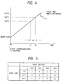
- the fixing ability greatly depends upon the input voltage. If the input voltage is low, since the fixing ability is apparently poor, by using the correction coefficient of 1.5, the temperature increase gradient index is determined while reflecting the influence of the input voltage, thereby calculating the environmental index (step S13). By comparing the environmental index determined in this way with a predetermined threshold value, the warm-up mode is determined.
- a high temperature mode is used when the environmental index is greater than 17 (steps S14 and S15), an intermediate temperature mode is used when the environmental index is smaller than 17 and greater than 12 (steps S16 and S17), and a low temperature mode is used when the environmental index is smaller than 12 (steps S16 to S18).
- the input voltage is 100 V (design reference value) and the heat capacities of the fixing roller, heater output and the like have also the design reference values, if the room temperature is higher than 17°C the high temperature mode is used, if the room temperature is lower than 17°C and higher than 12°C the intermediate temperature mode is used, and if the room temperature is lower than 12°C the low temperature mode is used.
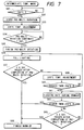
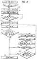
- Figs. 6, 7, 8 and 9 show flow charts regarding the warm-up operations in the high temperature mode, intermediate temperature mode, low temperature mode and deteriorate mode, respectively.
- step S21 When the high temperature mode is started, as shown in Fig. 6, the heater 12 is fully energized until the temperature of the heat roller 10 reaches 175°C (step S21). Then, a time period from a time when the communication to the heater 12 is started to a time when the temperature of the heat roller 10 reaches 175°C is measured (step S22). If the time period is longer than 28 seconds, the pre-multi rotation is effected by two seconds (steps S23 and S24), and then, the warm-up is finished (step S25).
- step S26 when the temperature of the heat roller 10 reaches 175°C, the pre-multi rotation is started (step S26), and the pre-multi rotation is continued until 30 seconds is elapsed after the communication to the heater 12 is started (step S27).
- the heater 12 When the intermediate temperature mode is started, as shown in Fig. 7, the heater 12 is fully energized until the temperature of the heat roller 10 reaches 190°C (step S31). As soon as the temperature of the heat roller reaches 190°C, the pre-multi rotation is started (step S32). After the target temperature is set to 205°C (step S33), the pre-multi rotation is continued for 7 seconds (step S34). After the pre-multi rotation is finished (step S35), the heater 12 is fully energized (step S36), and, it is judged whether 2.5 seconds is elapsed after the pre-multi rotation is finished (step S37).
- step S37, S38 If 2.5 seconds is elapsed, the warm-up is finished (steps S37, S38); whereas, if 2.5 seconds is not elapsed, the temperature adjustment for the target temperature of 205°C is started (step S39), and, the full lightening of the heater is continued until 200°C is reached (steps S40 ⁇ S36 ⁇ S37 ⁇ S39 ⁇ S40).
- step S41 the heater 12 is lightened at a predetermined flashing ratio
- step S43 when 205°C is reached (step S42) or when 2.5 seconds is elapsed after completion of the pre-multi rotation (step S43), the warm-up is finished (step S38).
- the heater 12 When the low temperature mode is started, as shown in Fig. 8, the heater 12 is fully energized until the temperature of the heat roller 10 reaches 190°C (step S51). As soon as the temperature of the heat roller reaches 190°C, the pre-multi rotation is started (step S52). After the target temperature is set to 205°C (step S53), the pre-multi rotation is continued for 27 seconds (step S54). After the pre-multi rotation is finished (step S55), the heater 12 is fully energized (step S56), and, it is judged whether 2.5 seconds is elapsed after the pre-multi rotation is finished (step S57).
- step S57 and S58 If 2.5 seconds is elapsed, the warm-up is finished (steps S57 and S58); whereas, if 2.5 seconds is not elapsed, the temperature adjustment for the target temperature of 205°C is started (step S59), and, the full lightening of the heater is continued until 200°C is reached (steps S60 ⁇ S56 ⁇ S57 ⁇ S59 ⁇ S60).
- step S61 the heater 12 is lightened at a predetermined flashing ratio
- step S63 when 205°C is reached (step S62) or when 2.5 seconds is elapsed after completion of the pre-multi rotation (step S63), the warm-up is finished (step S58).
- the heater 12 When the deteriorate temperature mode is started, as shown in Fig. 9, the heater 12 is fully energized until the temperature of the heat roller 10 reaches 190°C (step S71). As soon as the temperature of the heat roller reaches 190°C, the pre-multi rotation is started (step S72). After the target temperature is set to 205°C (step S73), the pre-multi rotation is continued for 55 seconds (step S74). After the pre-multi rotation is finished (step S75), the heater 12 is fully energized (step S76), and, it is judged whether 2.5 seconds is elapsed after the pre-multi rotation is finished (step S77).
- step S77 and S78 If 2.5 seconds is elapsed, the warm-up is finished (steps S77 and S78); whereas, if 2.5 seconds is not elapsed, the temperature adjustment for the target temperature of 205°C is started (step S79), and, the full lightening of the heater is continued until 200°C is reaches (steps S80 ⁇ S76 ⁇ S77 ⁇ S79 ⁇ S80).
- step S81 the heater 12 is lightened at a predetermined flashing ratio
- step S83 when 205°C is reached (step S82) or when 2.5 seconds is elapsed after completion of the pre-multi rotation (step S83), the warm-up is finished (step S78).
- the environmental index is determined by measuring the actual temperature change in the fixing roller, it is possible to perform the control in consideration of the environmental conditions directly affecting an influence upon the fixing ability. Further, by switching the warm-up modes on the basis of the environmental index, it is possible to obtain the fixing ability which is always satisfactory. In addition, excessive long warm-up time period can be avoided.
- the temperature adjustment temperature during the fixing operation is determined on the basis of the environmental index. Since the smaller the environmental index the more the fixing is difficult, it is apparent that the fixing ability is differentiated even when the fixing is effected at the same fixing temperature adjustment temperature under conditions that the environmental indexes are different from each other. Accordingly, by altering the fixing temperature adjustment temperature in accordance with the environmental index, the fixing ability can be kept constant.
- the factor (among factors for determining the environmental index) affecting the greatest influence upon the fixing ability is the room temperature.
- the influence of the input voltage upon the fixing ability is small in comparison with initial condition (rising condition).
- the countermeasure cannot be effected on the basis of the temperature adjustment temperature, and, thus, the wattage of the heater must be improved. That is to say, although the environmental index is determined on the basis of the room temperature index and the temperature increase gradient index, by determining the environmental index by weighing the room temperature index, it is possible to control the temperature adjustment temperature for obtaining the fixing ability which is satisfactory.
- the correction coefficient A for seeking the environmental index was 1.5.
- the correction coefficient is 1.2.
- the room temperature is made preferential in comparison with the first embodiment, thereby providing the control suitable to the actual fixing ability.
- This is referred to as "environmental index 2" for discrimination from the above-mentioned environmental index used in the initial condition.
- Fig. 10 is a flow chart for determining the temperature adjustment temperature in the second embodiment.
- step S91 when a main power source of the image forming apparatus is turned ON, the communication to the fixing heater 12 is started (step S91), and count of a timer is started (step S92), and a target temperature of temperature adjustment is set to 200°C (step S93). Then, a time period t c until the output from the thermistor 13 reaches 120°C is measured (steps S94 and S95), and a time period t a until the output reaches 150°C is measured (steps S96 and S97).
- the temperature adjustment temperature during the image formation and the stand-by temperature adjustment temperature during the stand-by condition are determined.
- the respective temperature adjustment temperatures are set to become relatively low, and, thus, the stand-by temperature adjustment temperature is set to 200°C and the temperature adjustment temperature during the image formation is set to 190°C (steps S100, S101 and S102).
- the temperature adjustment temperatures are slightly increased, and, thus, the stand-by temperature adjustment temperature is set to 205°C and the temperature adjustment temperature during the image formation is set to 195°C (steps S103, S104 and S105).
- the temperature adjustment temperatures are further increased, and, thus, the stand-by temperature adjustment temperature is set to 210°C and the temperature adjustment temperature during the image formation is set to 200°C (steps S106 and S107).
- the stand-by temperature adjustment temperature mainly affects an influence upon several copies in the initial condition of the image formation.
- the heat is absorbed to the pressure roller to swiftly decrease the temperature of the fixing roller, thus worsening the fixing ability.
- the heat amount required for initial fixing cannot be supplied sufficiently, it is desirable that the heat amount is accumulated during the stand-by as much as possible.
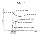
- the surface temperature of the heat roller starts to decrease after the pre-multi rotation of the image forming operation is started.
- the heat amount corresponding to the temperature decrease of the heat roller is supplied to the pressure roller and the paper sheet.
- the decrease in temperature of the heat roller is stopped, and the temperature of the heat roller starts to increase.
- the time period until the temperature of the heat roller reaches the minimum point and a temperature at the minimum point depend upon the stand-by temperature adjustment temperature. The higher the stand-by temperature adjustment temperature the higher the temperature at the minimum point.
- the stand-by temperature adjustment temperature is so set that the temperature at the minimum point is suppressed to provide the satisfactory fixing ability.
- the environmental index was determined on the basis of the room temperature index and the temperature increase gradient index.
- the temperature increase gradient index serves to correct the weighing of factors affecting an influence upon the environmental index. Further, in the first and second embodiments, the temperature increase gradient was corrected by using the linear function and the correction coefficient. However, when more general consideration regarding the environmental index is applied, the correction using the linear function may be insufficient.
- the environmental index is calculated, and the rising control and the temperature adjustment temperature control are determined.
Landscapes
- Physics & Mathematics (AREA)
- General Physics & Mathematics (AREA)
- Fixing For Electrophotography (AREA)
- Control Or Security For Electrophotography (AREA)
- Control Of Temperature (AREA)
Applications Claiming Priority (2)
| Application Number | Priority Date | Filing Date | Title |
|---|---|---|---|
| JP240822/94 | 1994-09-09 | ||
| JP24082294A JP3596821B2 (ja) | 1994-09-09 | 1994-09-09 | 画像形成装置 |
Publications (3)
| Publication Number | Publication Date |
|---|---|
| EP0701182A2 true EP0701182A2 (fr) | 1996-03-13 |
| EP0701182A3 EP0701182A3 (fr) | 1998-12-09 |
| EP0701182B1 EP0701182B1 (fr) | 2006-12-20 |
Family
ID=17065218
Family Applications (1)
| Application Number | Title | Priority Date | Filing Date |
|---|---|---|---|
| EP95306296A Expired - Lifetime EP0701182B1 (fr) | 1994-09-09 | 1995-09-08 | Dispositif de fixage |
Country Status (4)
| Country | Link |
|---|---|
| US (1) | US5987275A (fr) |
| EP (1) | EP0701182B1 (fr) |
| JP (1) | JP3596821B2 (fr) |
| DE (1) | DE69535345T2 (fr) |
Families Citing this family (15)
| Publication number | Priority date | Publication date | Assignee | Title |
|---|---|---|---|---|
| JP4193383B2 (ja) * | 2001-07-24 | 2008-12-10 | ブラザー工業株式会社 | 定着装置及び、該定着装置を備えた画像形成装置 |
| JP2004126191A (ja) * | 2002-10-02 | 2004-04-22 | Canon Inc | 画像形成装置 |
| JP4078235B2 (ja) * | 2003-03-26 | 2008-04-23 | キヤノン株式会社 | 加熱装置 |
| FR2862134B1 (fr) * | 2003-11-12 | 2007-07-27 | Sebia Sa | Analyse et typage de proteines monoclonales par electrophorese capillaire et immunodeplacement |
| US20050117917A1 (en) * | 2003-12-02 | 2005-06-02 | Samsung Electronics Co., Ltd. | Printing method and image forming apparatus having adjustable warm-up-time |
| JP2005258036A (ja) * | 2004-03-11 | 2005-09-22 | Konica Minolta Business Technologies Inc | 画像形成装置 |
| JP4642518B2 (ja) * | 2004-03-29 | 2011-03-02 | キヤノン株式会社 | 画像形成装置 |
| JP4246102B2 (ja) * | 2004-04-14 | 2009-04-02 | シャープ株式会社 | 定着装置およびそれを備えた画像形成装置 |
| JP4687043B2 (ja) * | 2004-09-10 | 2011-05-25 | 富士ゼロックス株式会社 | 定着装置 |
| JP2007108297A (ja) | 2005-10-12 | 2007-04-26 | Canon Inc | 画像形成装置 |
| JP5015675B2 (ja) * | 2007-06-27 | 2012-08-29 | 株式会社リコー | 加熱装置および定着装置ならびに画像形成装置 |
| US8023851B2 (en) * | 2008-07-18 | 2011-09-20 | Lexmark International, Inc. | Method and printer assembly for consistent power control in fuser assembly of electrophotographic printer |
| US9507299B1 (en) * | 2015-09-17 | 2016-11-29 | Kabushiki Kaisha Toshiba | Fixing device and image forming apparatus |
| CN111579595A (zh) * | 2019-02-19 | 2020-08-25 | 安徽康佳同创电器有限公司 | 一种气味传感器环境指数修正方法、系统及气味传感器 |
| US12411442B2 (en) * | 2022-08-09 | 2025-09-09 | Canon Kabushiki Kaisha | Image forming apparatus that changes a fixing condition based on temperatures of a heating member detected at different times |
Family Cites Families (13)
| Publication number | Priority date | Publication date | Assignee | Title |
|---|---|---|---|---|
| JPH0830930B2 (ja) * | 1987-01-20 | 1996-03-27 | キヤノン株式会社 | 定着装置 |
| JP2541972B2 (ja) * | 1987-04-11 | 1996-10-09 | 株式会社リコー | 定着装置の温度制御装置 |
| US5140132A (en) * | 1988-12-29 | 1992-08-18 | Seikosha Co., Ltd. | Method of and apparatus for controlling fixing device in electrophotographic recording system |
| JP2926406B2 (ja) * | 1989-01-06 | 1999-07-28 | コニカ株式会社 | 記録装置の定着部の予備回転制御方法 |
| JPH0343777A (ja) * | 1989-07-11 | 1991-02-25 | Brother Ind Ltd | 画像形成装置 |
| US5162855A (en) * | 1990-06-13 | 1992-11-10 | Konica Corporation | Image forming apparatus having temperature sensor for estimating the off time of the fuser as related to the platen glass temperature |
| JP2991240B2 (ja) * | 1990-07-31 | 1999-12-20 | 京セラ株式会社 | ローラ式熱定着器の加熱制御方法 |
| JPH04250483A (ja) * | 1991-01-10 | 1992-09-07 | Minolta Camera Co Ltd | 作像装置における定着装置 |
| JPH04282653A (ja) * | 1991-03-12 | 1992-10-07 | Casio Electron Mfg Co Ltd | 画像形成装置 |
| JP2915615B2 (ja) * | 1991-04-22 | 1999-07-05 | キヤノン株式会社 | 定着装置 |
| JP2925366B2 (ja) * | 1991-07-17 | 1999-07-28 | キヤノン株式会社 | 画像形成装置 |
| JP3170857B2 (ja) * | 1992-03-27 | 2001-05-28 | キヤノン株式会社 | 加熱装置 |
| JPH0643788A (ja) * | 1992-07-27 | 1994-02-18 | Canon Inc | 定着装置 |
-
1994
- 1994-09-09 JP JP24082294A patent/JP3596821B2/ja not_active Expired - Fee Related
-
1995
- 1995-09-08 DE DE69535345T patent/DE69535345T2/de not_active Expired - Lifetime
- 1995-09-08 EP EP95306296A patent/EP0701182B1/fr not_active Expired - Lifetime
-
1997
- 1997-03-04 US US08/796,690 patent/US5987275A/en not_active Expired - Fee Related
Non-Patent Citations (1)
| Title |
|---|
| None |
Also Published As
| Publication number | Publication date |
|---|---|
| JP3596821B2 (ja) | 2004-12-02 |
| EP0701182B1 (fr) | 2006-12-20 |
| DE69535345T2 (de) | 2007-07-19 |
| US5987275A (en) | 1999-11-16 |
| DE69535345D1 (de) | 2007-02-01 |
| JPH0883016A (ja) | 1996-03-26 |
| EP0701182A3 (fr) | 1998-12-09 |
Similar Documents
| Publication | Publication Date | Title |
|---|---|---|
| US5987275A (en) | Fixing apparatus with power control based on temperature gradient | |
| US4603245A (en) | Temperature control apparatus | |
| EP0390168B1 (fr) | Appareil de fixage d'images | |
| US5656187A (en) | Image fixing apparatus with power supply control based in part on heating resistor temperature | |
| US5572306A (en) | Image forming apparatus capable of setting fixing temperature corresponding to temperature rising state of heating member | |
| US6615003B2 (en) | Image forming apparatus | |
| US5517284A (en) | Fixing device | |
| EP0670531A2 (fr) | Installation de réglage de température pour un dispositif de fixage d'un appareil de génération d'image | |
| US7010241B2 (en) | Image forming apparatus, image forming method, and fixing device thereof | |
| US4887122A (en) | Copying machine | |
| JP2000227732A (ja) | 定着装置及び画像形成装置 | |
| JP4659195B2 (ja) | 定着装置および画像形成装置 | |
| JP2647966B2 (ja) | 画像形成装置 | |
| JPH0887197A (ja) | 定着装置 | |
| JP3124680B2 (ja) | ファクシミリ装置 | |
| JPS63173088A (ja) | 画像形成装置の定着装置 | |
| JP2000039800A (ja) | 画像形成装置 | |
| JPH0713462A (ja) | 定着装置の制御装置 | |
| JPH05119667A (ja) | 画像形成装置 | |
| JP3740258B2 (ja) | 画像形成装置 | |
| JP2000259035A (ja) | 画像形成装置 | |
| JPS59140526A (ja) | 温度制御装置 | |
| JPH1078728A (ja) | 定着装置及び画像形成装置 | |
| JPH04199176A (ja) | 定着制御装置 | |
| JPH11190958A (ja) | 定着装置 |
Legal Events
| Date | Code | Title | Description |
|---|---|---|---|
| PUAI | Public reference made under article 153(3) epc to a published international application that has entered the european phase |
Free format text: ORIGINAL CODE: 0009012 |
|
| AK | Designated contracting states |
Kind code of ref document: A2 Designated state(s): DE FR GB IT |
|
| PUAL | Search report despatched |
Free format text: ORIGINAL CODE: 0009013 |
|
| AK | Designated contracting states |
Kind code of ref document: A3 Designated state(s): DE FR GB IT |
|
| 17P | Request for examination filed |
Effective date: 19990421 |
|
| 17Q | First examination report despatched |
Effective date: 20010731 |
|
| GRAP | Despatch of communication of intention to grant a patent |
Free format text: ORIGINAL CODE: EPIDOSNIGR1 |
|
| GRAS | Grant fee paid |
Free format text: ORIGINAL CODE: EPIDOSNIGR3 |
|
| GRAA | (expected) grant |
Free format text: ORIGINAL CODE: 0009210 |
|
| AK | Designated contracting states |
Kind code of ref document: B1 Designated state(s): DE FR GB IT |
|
| PG25 | Lapsed in a contracting state [announced via postgrant information from national office to epo] |
Ref country code: IT Free format text: LAPSE BECAUSE OF FAILURE TO SUBMIT A TRANSLATION OF THE DESCRIPTION OR TO PAY THE FEE WITHIN THE PRESCRIBED TIME-LIMIT;WARNING: LAPSES OF ITALIAN PATENTS WITH EFFECTIVE DATE BEFORE 2007 MAY HAVE OCCURRED AT ANY TIME BEFORE 2007. THE CORRECT EFFECTIVE DATE MAY BE DIFFERENT FROM THE ONE RECORDED. Effective date: 20061220 |
|
| REG | Reference to a national code |
Ref country code: GB Ref legal event code: FG4D |
|
| REF | Corresponds to: |
Ref document number: 69535345 Country of ref document: DE Date of ref document: 20070201 Kind code of ref document: P |
|
| EN | Fr: translation not filed | ||
| PLBE | No opposition filed within time limit |
Free format text: ORIGINAL CODE: 0009261 |
|
| STAA | Information on the status of an ep patent application or granted ep patent |
Free format text: STATUS: NO OPPOSITION FILED WITHIN TIME LIMIT |
|
| 26N | No opposition filed |
Effective date: 20070921 |
|
| PG25 | Lapsed in a contracting state [announced via postgrant information from national office to epo] |
Ref country code: FR Free format text: LAPSE BECAUSE OF FAILURE TO SUBMIT A TRANSLATION OF THE DESCRIPTION OR TO PAY THE FEE WITHIN THE PRESCRIBED TIME-LIMIT Effective date: 20070810 |
|
| GBPC | Gb: european patent ceased through non-payment of renewal fee |
Effective date: 20070908 |
|
| PG25 | Lapsed in a contracting state [announced via postgrant information from national office to epo] |
Ref country code: FR Free format text: LAPSE BECAUSE OF FAILURE TO SUBMIT A TRANSLATION OF THE DESCRIPTION OR TO PAY THE FEE WITHIN THE PRESCRIBED TIME-LIMIT Effective date: 20061220 Ref country code: GB Free format text: LAPSE BECAUSE OF NON-PAYMENT OF DUE FEES Effective date: 20070908 |
|
| PGFP | Annual fee paid to national office [announced via postgrant information from national office to epo] |
Ref country code: DE Payment date: 20100930 Year of fee payment: 16 |
|
| REG | Reference to a national code |
Ref country code: DE Ref legal event code: R119 Ref document number: 69535345 Country of ref document: DE Effective date: 20120403 |
|
| PG25 | Lapsed in a contracting state [announced via postgrant information from national office to epo] |
Ref country code: DE Free format text: LAPSE BECAUSE OF NON-PAYMENT OF DUE FEES Effective date: 20120403 |