EP0701889A2 - Matrice pour le pressage isostatique de carreaux en céramique et procédé de fabrication des carreaux - Google Patents
Matrice pour le pressage isostatique de carreaux en céramique et procédé de fabrication des carreaux Download PDFInfo
- Publication number
- EP0701889A2 EP0701889A2 EP95202233A EP95202233A EP0701889A2 EP 0701889 A2 EP0701889 A2 EP 0701889A2 EP 95202233 A EP95202233 A EP 95202233A EP 95202233 A EP95202233 A EP 95202233A EP 0701889 A2 EP0701889 A2 EP 0701889A2
- Authority
- EP
- European Patent Office
- Prior art keywords
- die
- plate
- membrane
- cavity
- vulcanisation
- Prior art date
- Legal status (The legal status is an assumption and is not a legal conclusion. Google has not performed a legal analysis and makes no representation as to the accuracy of the status listed.)
- Granted
Links
- 238000003825 pressing Methods 0.000 title claims abstract description 46
- 239000000919 ceramic Substances 0.000 title claims abstract description 12
- 238000000034 method Methods 0.000 title claims description 13
- 238000004519 manufacturing process Methods 0.000 title claims description 8
- 239000012528 membrane Substances 0.000 claims abstract description 111
- 239000012530 fluid Substances 0.000 claims abstract description 54
- 239000000843 powder Substances 0.000 claims abstract description 28
- 238000007789 sealing Methods 0.000 claims abstract description 20
- 238000006073 displacement reaction Methods 0.000 claims abstract description 10
- 238000004073 vulcanization Methods 0.000 claims description 42
- 239000000463 material Substances 0.000 claims description 22
- 238000004873 anchoring Methods 0.000 claims description 21
- 210000003456 pulmonary alveoli Anatomy 0.000 claims description 21
- 230000015572 biosynthetic process Effects 0.000 claims description 17
- 230000009467 reduction Effects 0.000 claims description 16
- 239000000126 substance Substances 0.000 claims description 11
- 230000009471 action Effects 0.000 claims description 9
- 239000002904 solvent Substances 0.000 claims description 9
- 229920001971 elastomer Polymers 0.000 claims description 7
- 238000009826 distribution Methods 0.000 claims description 5
- 239000000806 elastomer Substances 0.000 claims description 5
- 235000001674 Agaricus brunnescens Nutrition 0.000 claims description 2
- 238000011065 in-situ storage Methods 0.000 claims description 2
- 125000006850 spacer group Chemical group 0.000 claims description 2
- 238000005520 cutting process Methods 0.000 claims 1
- 238000005192 partition Methods 0.000 claims 1
- 230000008901 benefit Effects 0.000 abstract description 5
- 239000011159 matrix material Substances 0.000 description 16
- 230000002093 peripheral effect Effects 0.000 description 11
- 239000000872 buffer Substances 0.000 description 9
- 238000007667 floating Methods 0.000 description 9
- 239000002184 metal Substances 0.000 description 9
- 229910052751 metal Inorganic materials 0.000 description 9
- 239000000853 adhesive Substances 0.000 description 8
- 230000001070 adhesive effect Effects 0.000 description 8
- 239000010410 layer Substances 0.000 description 8
- 230000036961 partial effect Effects 0.000 description 7
- 239000004794 expanded polystyrene Substances 0.000 description 6
- 238000003780 insertion Methods 0.000 description 5
- 230000037431 insertion Effects 0.000 description 5
- 230000007547 defect Effects 0.000 description 4
- 239000007789 gas Substances 0.000 description 4
- 239000000203 mixture Substances 0.000 description 4
- 239000011241 protective layer Substances 0.000 description 4
- IJGRMHOSHXDMSA-UHFFFAOYSA-N Atomic nitrogen Chemical compound N#N IJGRMHOSHXDMSA-UHFFFAOYSA-N 0.000 description 2
- UIIMBOGNXHQVGW-UHFFFAOYSA-M Sodium bicarbonate Chemical compound [Na+].OC([O-])=O UIIMBOGNXHQVGW-UHFFFAOYSA-M 0.000 description 2
- XSTXAVWGXDQKEL-UHFFFAOYSA-N Trichloroethylene Chemical group ClC=C(Cl)Cl XSTXAVWGXDQKEL-UHFFFAOYSA-N 0.000 description 2
- 238000005266 casting Methods 0.000 description 2
- 238000005056 compaction Methods 0.000 description 2
- 239000002131 composite material Substances 0.000 description 2
- 230000005489 elastic deformation Effects 0.000 description 2
- 238000010304 firing Methods 0.000 description 2
- -1 for example Substances 0.000 description 2
- 238000007373 indentation Methods 0.000 description 2
- 230000000670 limiting effect Effects 0.000 description 2
- 239000007788 liquid Substances 0.000 description 2
- 238000003754 machining Methods 0.000 description 2
- 238000002844 melting Methods 0.000 description 2
- 230000008018 melting Effects 0.000 description 2
- 230000002829 reductive effect Effects 0.000 description 2
- UBOXGVDOUJQMTN-UHFFFAOYSA-N trichloroethylene Natural products ClCC(Cl)Cl UBOXGVDOUJQMTN-UHFFFAOYSA-N 0.000 description 2
- 239000004793 Polystyrene Substances 0.000 description 1
- 230000000903 blocking effect Effects 0.000 description 1
- 238000007664 blowing Methods 0.000 description 1
- NEHMKBQYUWJMIP-NJFSPNSNSA-N chloro(114C)methane Chemical compound [14CH3]Cl NEHMKBQYUWJMIP-NJFSPNSNSA-N 0.000 description 1
- 239000004927 clay Substances 0.000 description 1
- 239000011248 coating agent Substances 0.000 description 1
- 238000000576 coating method Methods 0.000 description 1
- 150000001875 compounds Chemical class 0.000 description 1
- 230000006835 compression Effects 0.000 description 1
- 238000007906 compression Methods 0.000 description 1
- 238000001816 cooling Methods 0.000 description 1
- 230000008878 coupling Effects 0.000 description 1
- 238000010168 coupling process Methods 0.000 description 1
- 238000005859 coupling reaction Methods 0.000 description 1
- 238000011038 discontinuous diafiltration by volume reduction Methods 0.000 description 1
- 230000000694 effects Effects 0.000 description 1
- 239000013013 elastic material Substances 0.000 description 1
- 230000008030 elimination Effects 0.000 description 1
- 238000003379 elimination reaction Methods 0.000 description 1
- 235000011194 food seasoning agent Nutrition 0.000 description 1
- 238000010438 heat treatment Methods 0.000 description 1
- 238000000462 isostatic pressing Methods 0.000 description 1
- 239000007769 metal material Substances 0.000 description 1
- 238000003801 milling Methods 0.000 description 1
- 229910052757 nitrogen Inorganic materials 0.000 description 1
- 235000011837 pasties Nutrition 0.000 description 1
- 229920000642 polymer Polymers 0.000 description 1
- 239000002861 polymer material Substances 0.000 description 1
- 229920002223 polystyrene Polymers 0.000 description 1
- 230000000750 progressive effect Effects 0.000 description 1
- 230000002441 reversible effect Effects 0.000 description 1
- 239000004576 sand Substances 0.000 description 1
- 238000005488 sandblasting Methods 0.000 description 1
- 229910000030 sodium bicarbonate Inorganic materials 0.000 description 1
- 235000017557 sodium bicarbonate Nutrition 0.000 description 1
- 239000002195 soluble material Substances 0.000 description 1
- 238000005507 spraying Methods 0.000 description 1
- 230000007847 structural defect Effects 0.000 description 1
- 238000006467 substitution reaction Methods 0.000 description 1
- XLYOFNOQVPJJNP-UHFFFAOYSA-N water Substances O XLYOFNOQVPJJNP-UHFFFAOYSA-N 0.000 description 1
Images


Classifications
-
- B—PERFORMING OPERATIONS; TRANSPORTING
- B28—WORKING CEMENT, CLAY, OR STONE
- B28B—SHAPING CLAY OR OTHER CERAMIC COMPOSITIONS; SHAPING SLAG; SHAPING MIXTURES CONTAINING CEMENTITIOUS MATERIAL, e.g. PLASTER
- B28B3/00—Producing shaped articles from the material by using presses; Presses specially adapted therefor
- B28B3/003—Pressing by means acting upon the material via flexible mould wall parts, e.g. by means of inflatable cores, isostatic presses
-
- B—PERFORMING OPERATIONS; TRANSPORTING
- B30—PRESSES
- B30B—PRESSES IN GENERAL
- B30B11/00—Presses specially adapted for forming shaped articles from material in particulate or plastic state, e.g. briquetting presses, tabletting presses
- B30B11/001—Presses specially adapted for forming shaped articles from material in particulate or plastic state, e.g. briquetting presses, tabletting presses using a flexible element, e.g. diaphragm, urged by fluid pressure; Isostatic presses
-
- B—PERFORMING OPERATIONS; TRANSPORTING
- B30—PRESSES
- B30B—PRESSES IN GENERAL
- B30B15/00—Details of, or accessories for, presses; Auxiliary measures in connection with pressing
- B30B15/02—Dies; Inserts therefor; Mounting thereof; Moulds
- B30B15/022—Moulds for compacting material in powder, granular of pasta form
- B30B15/024—Moulds for compacting material in powder, granular of pasta form using elastic mould parts
-
- B—PERFORMING OPERATIONS; TRANSPORTING
- B30—PRESSES
- B30B—PRESSES IN GENERAL
- B30B5/00—Presses characterised by the use of pressing means other than those mentioned in the preceding groups
- B30B5/02—Presses characterised by the use of pressing means other than those mentioned in the preceding groups wherein the pressing means is in the form of a flexible element, e.g. diaphragm, urged by fluid pressure
Definitions
- the invention concerns a die for pressing ceramic tiles and a relative manufacturing method.
- the prior art comprises Italian patent for industrial invention IT-B-1104511 in which the ceramic tiles are pressed under the action of an elastic modelling membrane, for example, made of rubber, delimiting a chamber in a relative semi-die in which an incompressible fluid, for example, oil, is introduced; by means of such a die it is possible to make the density of the pressed tiles homogeneous so as to limit undesired dimensional variations during their subsequent firing.
- an elastic modelling membrane for example, made of rubber
- the same patent also proposes the use of stiffer plates applied to the external surface of the elastic modelling membrane with a view to limiting excessive deformation in the membrane.
- the areas corresponding to the support ribbing of the tile are not as well pressed and consequently the corresponding areas on the opposite face have a greater porosity, with an unacceptable variation in the surface finish and a considerable reduction, in these areas, in the mechanical strength of the support.
- Utility model IT-U-214739 proposes a die for ceramic tiles in which the body of a punch has a plurality of intercommunicating seats, filled with oil or other incompressible fluid, in which are inserted, with wet seal, pistons sliding in them in order to impart differentiated degree of compaction in the various zones of the mass of powders during pressing. Between the active ends of the said pistons and the powders to be pressed there being an elastically deformable membrane acting as a coating for the surface of the punch.
- the prior art also comprises a die described in the patent application IT-A-MO93A000068 in which the elastic membrane, on the side opposite to that in contact with the powders for forming the tile, is equipped with appendages, for example, each consisting of a cover made of an elastic material, preformed and cooperating with the walls of the alveolus to which the said cover is attached and on whose base its lower rim rests: during the operation of vulcanisation the said elastic cover forms an integral part of the said membrane, closing off the alveolus and so enabling the chamber for the incompressible fluid to remain free, delimited by the internal surface of the same cover.
- appendages for example, each consisting of a cover made of an elastic material, preformed and cooperating with the walls of the alveolus to which the said cover is attached and on whose base its lower rim rests: during the operation of vulcanisation the said elastic cover forms an integral part of the said membrane, closing off the alveolus and so enabling the chamber for the incompressible fluid to
- a further aspect of the technical problem is that of inventing an isobaric die for pressing substantially flat items, in particular, ceramic tiles, in which it is possible to maintain a substantially flat configuration of the plate and of the part of the membrane associated with it prior to pressing, in particular during the loading phase of the powders in the matrix of the relative semi-die; this in a simple and economical manner.
- a further aspect of the technical problem is that of inventing a method for the manufacture of isobaric dies that enables the elimination of all loss of active surface in the chambers defined by the alveoli that contain the incompressible fluid.
- Another aspect of the same technical problem being that of reducing the manufacturing costs of the isobaric dies.
- the invention resolves the said technical problem by adopting an isostatic die for pressing tiles, comprising a semi-die having a plate delimiting a cavity in the semi-die containing the incompressible fluid and anchored to the said semi-die by means of an elastic sealing element for the incompressible fluid in the said cavity, the said plate being free to perform limited displacements closer to, or further away from, the base of the said cavity, characterised in that the said plate has openings passing through it.
- the elastic element can consist of an elastic membrane anchored to the body of the semi-die along its edge and to the surface of the plate facing the powders to be pressed.
- the elastic element can be anchored along the edge of the said plate to the body of the semi-die so as to constitute an elastic hinge joint.
- the areas of discontinuity in the plate can consist of a regular formation of through holes made in the body of the said plate, or of a formation of incisions that subdivide the plate into a plurality of independent tiles, or of a formation of independent slots, for example, aligned and offset in mutually perpendicular directions.
- the presence of discontinuities in the plate determines displacements of the membrane only in planes substantially parallel to the forming plane: this achieves, with a given displacement of the tiles, the compaction of a greater volume of powder than is possible with a membrane that deforms in curved configurations; conversely, with a given volume of powder displaced in compensating for the non homogeneous loading of the matrix of the die, the displacement of the tiles in planes parallel to the forming planes is much less than that which would be required with curved deformations of the membrane.
- the displacements of the tiles in planes parallel to the forming plane afford a better compensation of pressing, also in the areas close to the ribbing, or appendages, where significant lack of homogeneity can be found when using prior art dies.
- the adoption of areas of discontinuity in the plate consisting of a regular formation of openings, arranged as in a chequred pattern enables the compensation during pressing of the non homogeneous loading of the matrix of areas a considerable distance apart as a result of the elastic deformation of the plate.
- the compensation between areas a short distance apart is obtained with the elastic deformation of the membrane in the areas of discontinuity in the plate. This enables local deformations of the membrane to be limited, thereby also limiting the structural defects of the pressed item.
- the areas of discontinuity in the plate are made cooperating with at least one appendage, or tie, or elastic anchoring element, fashioned in the surface of the membrane on the side facing the cavity and anchored in a corresponding seat fashioned in the base of the said cavity.
- the said appendage, or tie, or elastic anchoring element is advantageously made up of the same material as the membrane and is integral with it, in such a way that it passes through the said plate.
- the intermediate elastic anchorage elements can be offset with respect to the cavities set into the face of the membrane in contact with the powders to be pressed for the formation of the supporting elements of the pressed tile, or for their anchoring when they are laid.
- the intermediate elastic anchorage elements can be distributed in relation to ribs obtained in the floating plate, as defined by the formation of through openings made in the said plate: the cavities of the membrane destined to form the support appendages of the tile being positioned in relation to the said ribs.
- a method for the manufacture of an isobaric die for pressing ceramic tiles, having a plate delimiting a cavity of the semi-die in which is contained an incompressible fluid and anchored to the said semi-die by means of an elastic sealing element for the incompressible fluid in the said cavity, the said plate being free to perform limited displacements closer to, or further away from, the base of the said cavity, the method comprising the vulcanisation in situ of the said elastic element and the subsequent filling of the said cavity with the said incompressible fluid, characterised in that, prior to the said vulcanisation, a temporary support element, functionally reducible, having a profile matching that of the plan shape of the cavity, is inserted into the said cavity and that, after the said vulcanisation and before the said filling, the temporary support element is reduced.
- the cavity occupying the entire extension of the active surface of the die, can be divided into a plurality of alveoli in which sit the singular portions, or tiles, into which the plate is subdivided.
- the said temporary support element, or tablet can be made of a material which is soluble, and/or which may be shrunk, or collapsed, or dissolved, or incinerated using heat.
- the reduction of the said temporary support element can be achieved physically, or chemically.
- the temporary support element can have a thickness constituting a fraction of the depth of the alveolus, up to 50% or more.
- the reduction can be achieved with the mechanical reduction of the volume, or flattening, of the support element against the bottom of the alveolus.
- the said reduction can be achieved by melting.
- the material of the said tablet is expanded polystyrene, with a density of less than 150 kg/m3, conveniently 110 kg/m3 or even much less (down to approximately 60) in that it is more easily dissolved and disgregated.
- the reduction can be achieved chemically by introducing methyl chloride, or trichloroethylene, into the alveoli, after vulcanisation, through the hole used for the introduction of the incompressible fluid, letting it circulate for a few minutes then removing it through the hole used for the outlet of the incompressible fluid: in this way the chambers of the alveoli are freed for the subsequent introduction into them of the said fluid.
- the reduction of the tablets can be achieved physically (with volume reduction) by introducing, after the vulcanisation when the die is still in the forming press of the membrane, a suitable compressed gas, at a pressure of at least a few dozen bar, through the same hole, so as also to flatten the said tablet.
- Increasing the pressure is advantageously associated with an increase in the temperature of the compressed gas, up to the melting point of expanded polystyrene, whereupon the melted residue is possibly evacuated.
- the thickness of the tablet may vary from approximately 1 to approximately 5 mm, with a depth of alveolus of between 8 and 10 mm.
- the choice of the soluble material for the tablet of the expanded polystyrene type requires that the top surface of the said tablet be protected with a layer of substance resistant to the solvents contained in the adhesives used in the vulcanisation of the membrane, for example, conveniently, by means of a thin metal sheet having points folded back to mount the tablet to it and to make it more easily introduced into the alveolus together with the said plate.
- each alveolus there being, in the walls of each alveolus, a peripheral groove that constitutes an undercut so as to obtain further and advantageous anchorage of the appendages of the elastic membrane that penetrated into the alveolus during the vulcanisation.
- the casting of the elastic membrane for example made of the material "CYANAPRENE" is followed, after approximately 5 minutes required for reticulation, with the closure of the die with a pressure of a few bar and heating to a temperature of almost 100 °C even up to 125 °C or more for approximately 10 minutes; seasoning at approximately 80 °C and cooling then follows.
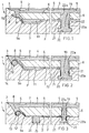
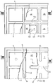
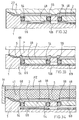
- the die for ceramic tiles comprises at least one semi-die 1, that is, the punch and/or buffer that may be inserted in a matrix M ( Figure 11), having an elastic membrane 2, anchored peripherally to the frame 3 of the semi-die 1, and having, on its external face, a surface 4 having the profile of one of the faces of tile to be formed, for example, the rear face, as shown.
- a matrix M Figure 11
- grooves 5, or indents can be provided to form the projections in the rear face of the tile, to enable it to be laid and/or transported during the various phases of the production cycle.
- the membrane 2 is coupled, in relation to its innermost face, with a floating forming plate 6 delimiting a chamber 7 in which an incompressible fluid, for example, pressurised oil, is introduced: the cavity 7 extends underneath the forming plate 6, up to its peripheral edge so that the incompressible fluid F contained in it may act uniformly substantially over the entire extent of the said plate.
- an incompressible fluid for example, pressurised oil
- the plate 6 is preferably inserted in cavity 7 in such a way as to occupy the entire surface of the tile to be pressed: that is, the said plate extends laterally up to the groove, or cavity, 5 destined to form the outermost rib or, respectively, appendage of the tile.
- the membrane 2 is anchored to the frame 3 of the semi-die 1 in such a way as to define a peripheral seal having a first lip 8 inserted in said cavity and provided with peripheral appendage 9 extending into a corresponding seat 10 to create a seal in a plane parallel to the plane in which the membrane 6 lies, so as to eliminate the risk of the incompressible fluid, for example, pressurised oil, escaping from the cavity during pressing with the detachment of the said first lip 8.
- the incompressible fluid for example, pressurised oil
- the membrane 2 is also provided with a second lip 9a, derived from the said first lip 8 in the opposite direction with respect to its appendage 9.
- the second lip 9a is wound round the peripheral edge of the forming plate 6 and possibly extends with a portion 11 under the said plate, as shown in Figures 1 and 2.
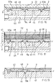
- the lip 8 extends, on the opposite side to that of the plate, so as to wind round a forming element 12, having an annular shape and preferably a circular transverse cross-section, and ending with its extremity 13 in a seat 14 beside the forming element 12.
- extremity 13 corresponds to appendage 9 already described with reference to the version of die as in Figure 1, but differs from it in that it is wound round forming element 12.
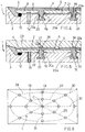
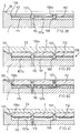
- the membrane 2 is also preferably provided with at least one intermediate elastic anchoring element 19, passing through a discontinuity, or opening, 22a in the forming plate 6 and anchored in a corresponding seat 20, advantageously with undercut, on the bottom of the cavity 7.
- seat 20 is made from a closed hole in the bottom of the cavity and has a base which is wider than its relative opening 20a.
- each intermediate elastic element 19 the walls of seat 20a are separated from the lateral surface of the relative element.
- the intermediate elastic element 19 also limits outward arching of the plate 6 when the cavity 7 is filled with incompressible fluid.
- the distribution of the intermediate traction elements 19 and the load carrying section of each of these have to be such as to generate on the plate 6 loads directed towards the bottom of the cavity 7 and to be of a magnitude that, when summed with the restraint distributed along the edge of the plate, they are substantially equivalent and opposed to the uniformly distributed load exerted by the pressure of the incompressible fluid, before pressing.
- the plate 6, and therefore the membrane 2 are maintained level, without altering the loading of the mixture of powders in the matrix of the die.
- the intermediate elastic traction element 19 can be provided with an intermediate annular projection 21, in the shape of a mushroom, firmly anchored to the plate 6 and inserted in a relative conjugate seat 22, made in the lower face of the plate 6 (Figure 3), or on the top face of the cavity 7 ( Figure 2): the function of the annular projection 21 is that of constituting a sealing element against oil leakage between the chamber 7 and the surface anchoring the membrane 2 to the plate 6 through the opening 22a.
- Each through opening 22a enables the formation of a corresponding elastic element 19 during vulcanisation of the membrane 2.
- membrane 2 is formed, with the relative elastic traction elements 19, by the action exerted on it, in a fluid or pasty state, by a vulcanising punch 23, whilst the conduit 7a is closed by a centering pin 24 for the plate 6.
- Figure 3 also shows 25, an elastic spacer element, for example a cylindrical helical compression spring, to facilitate the detachment of the plate 6 from the bottom of the cavity 7 after vulcanisation: the elastic element 25 is inserted in a seat 26 in the bottom of the cavity 7, advantageously positioned at the vertices of the said cavity, where the membrane is most likely to remain lying on the bottom of the cavity even after the cavity has been filled with incompressible fluid.
- an elastic spacer element for example a cylindrical helical compression spring
- the elastic traction elements 19 are distributed in oval, or elliptical, patterns shown with 27, 28: it being envisaged, for example, that the elastic elements 19 are positioned at the intersections between the directrix lines L, preferably passing through the centre C, such as the diagonals 29, 30 and/or median lines 31, 32 of the sides defining the bottom of the cavity and the said ellipses 27, 28.
- the distribution of the intermediate elastic elements 19 can be along circumferences 33, 34.
- the intermediate elastic elements 19 can have, for example, a slot-shaped cross-section 35.
- the membrane 2 can advantageously have, during the vulcanisation phase, projections 36 obtained with corresponding indentations in the forming punch, being shaped in such a way that, when the membrane is deformed as result of the insertion of the oil, its surface in contact with the tile to be pressed is substantially flat, that is, it does not have indentations caused by the pulling effect of the relative elastic element 19.
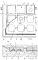
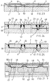
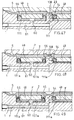
- the plate 39 has a number of openings 40, distributed in a chequered pattern, in which are inserted, during vulcanisation, the elastomer material constituting the membrane 2 and extending into the areas included between the grooves 5: in this way the membrane 2 and the plate 39 with its relative openings 40 together have a variable stiffness.
- the membrane 2 has areas with greater stiffness in the areas corresponding with the imprints 5, or grooves, or cavities for supporting the formed tile 41.
- the traction elements 19 of the membrane 2 towards the bottom of the cavity 7 can be situated in relation to the rigid parts of the said membrane, that is, in positions corresponding to those of the ribs 40a made in the floating plate 39, in this case being shown as 19a, as in the versions in Figures 12, 13, 14.
- the membrane 2 with the relative plate 39 has variable stiffness in the different areas of the tile, with the result that, where the tile is locally made up of a thinner or a thicker layer of powder than that which is theoretically envisaged, the membrane 2 and the plate 39 together deforms locally, in a corresponding manner, towards the tile 41 or towards the cavity 7.
- the floating plate 42 can have openings in the shape of slots and communicating with elastic anchoring elements 19a inserted in corresponding seats having the same slot shape 44, or extending, as with 19c, from one side of the cavity 7 to the opposite side ( Figure 15, 16, 17).
- membrane 2 initially curved towards the powders to be pressed, is made to take on a substantially flat configuration by the thrust of the fluid F during pressing by the punch PZ with a tensile load on the elastic elements 19a, the final trim depending on the local density of the powders.
- the floating plate is made discontinuous by means of a formation of longitudinal and transverse openings that subdivide it into a plurality of tiles 48, for example, quadrangular, inserted so as to be floating in corresponding seats 49 ( Figure 16) into which the cavity 7 is subdivided:
- the tiles 48 can have any plan view shape, for example, polygonal with rounded vertices, for example, rectangular, or square, or circular, or whichever other convenient shape.
- the seats 49 are made communicating by means of channels 60 and 61 for the incompressible fluid: the form of the seats 49 preferably being flared upwards and in any case such as to enable the formation, during vulcanisation, of lips 50a in the membrane 2 wrapping round each tile 48 so as to incorporate it into the relative membrane.
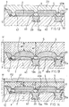
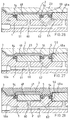
- Figures 20, 21 show how in this version the membrane 2 is anchored to a plurality of anchoring elements 51 having a "T"-shaped cross-section, for anchoring the said membrane in undercut: these elements also being provided with transverse through holes 52 to further improve anchoring.
- T-shaped anchoring elements 51 as shown in Figures 20, 21, preferably provided with transverse through holes 52, can also be provided for the version of floating plate 42 in Figures 22, 23.
- the tiles 48 being of considerable thickness and having smooth lateral surfaces 53, are made to co-operate with sealing rings 54 intended to prevent, during vulcanisation, leakage of the elastomer material the membrane 2 is made of towards the underlying seats 55, the said seats constituting integral parts of the chamber 7 for the incompressible fluid; the sealing rings 55 being inserted in stepped grooves 56 in the side walls of the seats 55.
- the stepped grooves 57 for the said sealing rings can be made in the side walls of the tiles 48.
- the tiles 48 can be positioned so that they are in contact with the bottom of the corresponding cavity 55 or raised from it, for example with the positioning between them of a fluid material , for example, granular, such as sand S, that is expelled after forming.
- a fluid material for example, granular, such as sand S, that is expelled after forming.
- the sealing rings 54 in order to allow a greater flexibility and to improve sealing against oil leakage from cavity 7, can be inserted in stepped seats 56a having a diameter which is essentially greater than the external diameter of the corresponding sealing element 54.
- the membrane 2 can have a smooth external surface 59 ( Figure 26) during the vulcanisation phase with matrix 23, the grooves, or cavities, 5 being obtained with the deformation of the membrane only with the introduction of the pressurised fluid in the cavity 7.
- the seats 55 for the tiles 48 being an integral part of the cavity 7 in which the incompressible fluid F is contained, can be made intercommunicating by means of channel 62 which has an axis bent in the shape of a "V" to connect one seat directly with the one adjacent to it.
- the tiles 48 can have smooth lateral surfaces and can be inserted in seats 55 also having smooth lateral surfaces.
- Each tile 48 can be made to operate with, at its lower end, a collapsible support element 65 consisting of a central flat element 66, which has, axially, a hole 67 passing through it and, peripherally, a concave annular edge defining a seat for centering the relative tile 48.
- the position of the central hole 67 has to correspond to that of the hole 60 of the semi-die 1.
- the collapsible support 65 is pushed down to the bottom of the seat 55 and the tile 48 remains firmly in contact with the membrane 2: between the side walls of the tile 48 and the side walls of the seat 55 there is an annular joint 68 made of the material of the membrane 2 that favour the floating movements of each tile 48.
- the membrane 2 can be limited to the ensemble of annular joints 68, that is, the tiles do not have to be lined with the elastomer material on its active face in pressing.
- the collapsible support 65 can be in the shape of a saucer 69 ( Figure 35), or cup, possibly with a central hole to accommodate a sealing element 70 having the function of the tile 48, destined to be an integral part of the membrane 2.
- the sealing element can also consist of a sphere 71, as shown in the right-hand part of Figure 35.
- the surface of the collapsible support 65 facing the membrane 2 can advantageously be lined with a non adhesive substance in order to prevent the undesirable adhesion between the said element and the membrane during vulcanisation.
- Figure 50 also shows a temporary collapsible support having a flat shape, for example, a ring 72, positioned, with overhang, in a stepped seat 73 in the alveolus, or seat 55.
- This particular type of temporary support element is preferable for its simplicity, in that it enables the use of commercially available rings, or washers, with a considerable saving in cost.
- the ring 72 can be deformed down towards the bottom of the cavity 55 with a preliminary pressing stroke by punch P: to make such a deformation possible the width D1 of each tile 48 is preferably less than the minimum width D2 of the relative seat 55.
- Figure 51 shows how the tiles 48a can even emerge at the pressing surface, in which case there are interruptions in corresponding parts of the membrane 2: the tiles 48a are each individually connected to a seat 55 by means respective annular joints 68.
- the die 1 can have a frame 3, with sloping peripheral portion 3a and horizontal positioning portion 104 corresponding to a first external row 105 (Figure 39) of support ribs of the tile, in bas-relief; 106, the alveoli of the buffer plate, delimited by ribs, or walls, 107 and bottom 107a; 108, opposing overlapping incisions made in either side of the base of each wall 107 to make each alveolus 106 intercommunicating, made, for example, using a radial milling cutter 109; 108a, a peripheral groove made in the middle-upper part of the alveolus to improve the anchorage of the elastic membrane; 110, ( Figure 37) an inlet conduit for the fluid at the bottom of the alveoli 106; 111, ( Figure 38) tablets made of a soluble and/or retractable or meltable material - for example, a low density expanded material such as expanded polystyrene of approximately 110 gr/dm3 - each inserted
- the elastic membrane is formed in the following way: once the buffer has been sandblasted to degrease it and to make it more suitable for retaining the used for anchoring the said membrane to the surfaces of the buffer and to the relative surfaces of the alveoli, the tablets 111 are inserted, advantageously together with the covering metal sheet 117, 118, which have to enter into the alveolus 106 with a clearance of the order of hundredths of a millimetre; the sandblasting is possibly repeated and the adhesive substance is applied, for example, by spraying, to the surfaces that are to come into contact with the said membrane, including the surface of the metal sheet; one the buffer is preheated to about 100-125 °C, the elastic forming substance of the membrane 2 is cast, for example, a polymer such as CYANAPRENE (manufactured by the company AIR PRODUCTS, Allentown, USA); having positioned a layer of non adhesive substance between the matrix 23 and the membrane 2, after approximately 5 minutes, required for reticulation, the die is
- the tablet 111 can have the function of collapsible support for the tile 48 positioned above it; with a deforming stroke of the punch P, the tablet 111a takes on a flattened configuration on the bottom 107a of each alveolus.
- the tablet can consist of clay, or slats (for example, sodium bicarbonate), or other substance or compound that is soluble, or miscible, in water.
- Figure 52 shows a collapsible support 111a made of expanded polystyrene positioned between the bottom of the cavity 7, in such a way as occupy it completely, and the innermost face of a plate 42.
- the plate is kept in position by the support element, or tablet, 111a, whereupon it is subsequently reduced, as described previously.
- the collapsible support element can also consist of a panel 90 (Figure 53) of composite material, comprising a pair of outer layers 91 between which is placed a reducible layer 92, for example, made of a corrugated metallic material.
- the reduction of the element 90 can be achieved by flattening it against the bottom of the cavity 7, or of the alveoli 55.
- the membrane 2, for example, that wraps around the plate 6, 48 can also consist of various polymer materials, for example, of a material with a high degree of elasticity for the anchorage areas 6, 68, 19, 19a, and of a stiffer material for the face of the plate 5, 48 facing the powders to be pressed.
Landscapes
- Engineering & Computer Science (AREA)
- Mechanical Engineering (AREA)
- Physics & Mathematics (AREA)
- Fluid Mechanics (AREA)
- Manufacturing & Machinery (AREA)
- Chemical & Material Sciences (AREA)
- Ceramic Engineering (AREA)
- Press-Shaping Or Shaping Using Conveyers (AREA)
- Compositions Of Oxide Ceramics (AREA)
Priority Applications (2)
| Application Number | Priority Date | Filing Date | Title |
|---|---|---|---|
| EP19960202189 EP0759346B1 (fr) | 1995-08-18 | 1996-08-05 | Matrice pour le pressage isostatique |
| ES96202189T ES2166860T3 (es) | 1995-08-18 | 1996-08-05 | Medio de prensado isostatico. |
Applications Claiming Priority (6)
| Application Number | Priority Date | Filing Date | Title |
|---|---|---|---|
| ITMO940127 | 1994-09-13 | ||
| ITMO940127 IT1269252B (it) | 1994-09-13 | 1994-09-13 | Stampo isobarico per la pressatura di manufatti ceramici, in particolare piastrelle, con membrana a tenuta di fluido perfezionata |
| ITMO940141 IT1269262B (it) | 1994-09-13 | 1994-10-11 | Stampo isobarico per la pressatura di piastrelle ceramiche, e metodo relativo |
| ITMO940141 | 1994-10-11 | ||
| IT94MO000175 IT1269288B (it) | 1994-12-28 | 1994-12-28 | Metodo per la formatura della membrana elastica nello stampo isobarico per piastrelle ceramiche e stampo relativo |
| ITMO940175 | 1994-12-28 |
Publications (3)
| Publication Number | Publication Date |
|---|---|
| EP0701889A2 true EP0701889A2 (fr) | 1996-03-20 |
| EP0701889A3 EP0701889A3 (fr) | 1996-07-10 |
| EP0701889B1 EP0701889B1 (fr) | 2002-07-24 |
Family
ID=27274119
Family Applications (1)
| Application Number | Title | Priority Date | Filing Date |
|---|---|---|---|
| EP95202233A Expired - Lifetime EP0701889B1 (fr) | 1994-09-13 | 1995-08-18 | Matrice pour le pressage isostatique de carreaux en céramique et procédé de fabrication des carreaux |
Country Status (5)
| Country | Link |
|---|---|
| EP (1) | EP0701889B1 (fr) |
| AT (1) | ATE220975T1 (fr) |
| DE (1) | DE69527479D1 (fr) |
| ES (1) | ES2179860T3 (fr) |
| IT (1) | IT1269262B (fr) |
Cited By (9)
| Publication number | Priority date | Publication date | Assignee | Title |
|---|---|---|---|---|
| EP0780202A3 (fr) * | 1995-12-18 | 1997-07-02 | F.D.S. S.r.l. | Demi matrice améliorée pour le pressage de carreaux en céramique |
| DE19629413A1 (de) * | 1996-07-22 | 1998-01-29 | Erlus Baustoffwerke | Keramischer Falzdachziegel |
| EP0865888A1 (fr) * | 1997-03-18 | 1998-09-23 | Annovi S.r.l. | Matrice pour le pressage isostatique de carreaux en céramique et méthode de fabrication de cette matrice |
| EP1132185A3 (fr) * | 2000-03-07 | 2002-10-23 | Franco Bagni | Partie de moule pour le pressage de carreaux en céramique |
| ES2181511A1 (es) * | 1999-05-19 | 2003-02-16 | Vicente Rafael Fernandez | Punzon hidraulico con deposito de aceite incorporado. |
| WO2006095254A3 (fr) * | 2005-03-09 | 2006-11-30 | Mira Di Algeri Maris | Dispositif de compression isostatique |
| EP1704975A3 (fr) * | 2005-03-25 | 2007-07-04 | C.B.M. - S.r.l. | Poinçon de presse pour formage dûne surface de pièces en céramique |
| IT201600079937A1 (it) * | 2016-07-29 | 2018-01-29 | I Dea Re S R L | Tampone per la formatura di piastrelle |
| IT201900002749A1 (it) * | 2019-02-26 | 2020-08-26 | Officina Ferrari Carlo Spa | Tampone per la pressatura di polveri |
Family Cites Families (5)
| Publication number | Priority date | Publication date | Assignee | Title |
|---|---|---|---|---|
| GB1160590A (en) * | 1967-03-20 | 1969-08-06 | Yuken Kogyo Co Ltd | An improved method and apparatus for the manufacture of Dish-Shaped Ceramic Articles |
| US4370120A (en) * | 1978-11-28 | 1983-01-25 | Foster Robert D | Compacting press with expandable body |
| US4937025A (en) * | 1987-09-30 | 1990-06-26 | Hydra Corporation | Molding apparatus and method |
| ES2112073T3 (es) * | 1993-03-17 | 1998-03-16 | Maris Algeri | Medios de molde, particularmente para el prensado de baldosas ceramicas. |
| IT1262344B (it) * | 1993-12-21 | 1996-06-19 | Mass Spa | Metodo e impianto per la formatura di piastrelle a compattazione e spessore uniformi, e piastrelle cosi' ottenute. |
-
1994
- 1994-10-11 IT ITMO940141 patent/IT1269262B/it active IP Right Grant
-
1995
- 1995-08-18 AT AT95202233T patent/ATE220975T1/de not_active IP Right Cessation
- 1995-08-18 DE DE69527479T patent/DE69527479D1/de not_active Expired - Lifetime
- 1995-08-18 EP EP95202233A patent/EP0701889B1/fr not_active Expired - Lifetime
- 1995-08-18 ES ES95202233T patent/ES2179860T3/es not_active Expired - Lifetime
Cited By (9)
| Publication number | Priority date | Publication date | Assignee | Title |
|---|---|---|---|---|
| EP0780202A3 (fr) * | 1995-12-18 | 1997-07-02 | F.D.S. S.r.l. | Demi matrice améliorée pour le pressage de carreaux en céramique |
| DE19629413A1 (de) * | 1996-07-22 | 1998-01-29 | Erlus Baustoffwerke | Keramischer Falzdachziegel |
| EP0865888A1 (fr) * | 1997-03-18 | 1998-09-23 | Annovi S.r.l. | Matrice pour le pressage isostatique de carreaux en céramique et méthode de fabrication de cette matrice |
| ES2181511A1 (es) * | 1999-05-19 | 2003-02-16 | Vicente Rafael Fernandez | Punzon hidraulico con deposito de aceite incorporado. |
| EP1132185A3 (fr) * | 2000-03-07 | 2002-10-23 | Franco Bagni | Partie de moule pour le pressage de carreaux en céramique |
| WO2006095254A3 (fr) * | 2005-03-09 | 2006-11-30 | Mira Di Algeri Maris | Dispositif de compression isostatique |
| EP1704975A3 (fr) * | 2005-03-25 | 2007-07-04 | C.B.M. - S.r.l. | Poinçon de presse pour formage dûne surface de pièces en céramique |
| IT201600079937A1 (it) * | 2016-07-29 | 2018-01-29 | I Dea Re S R L | Tampone per la formatura di piastrelle |
| IT201900002749A1 (it) * | 2019-02-26 | 2020-08-26 | Officina Ferrari Carlo Spa | Tampone per la pressatura di polveri |
Also Published As
| Publication number | Publication date |
|---|---|
| ITMO940141A1 (it) | 1996-04-11 |
| ATE220975T1 (de) | 2002-08-15 |
| ES2179860T3 (es) | 2003-02-01 |
| EP0701889B1 (fr) | 2002-07-24 |
| ITMO940141A0 (it) | 1994-10-11 |
| EP0701889A3 (fr) | 1996-07-10 |
| DE69527479D1 (de) | 2002-08-29 |
| IT1269262B (it) | 1997-03-26 |
Similar Documents
| Publication | Publication Date | Title |
|---|---|---|
| EP0701889A2 (fr) | Matrice pour le pressage isostatique de carreaux en céramique et procédé de fabrication des carreaux | |
| US6391250B1 (en) | Method for producing forms and foamed metal forms | |
| CA1319524C (fr) | Methode et dispositif d'obturation de fissures dans les structures de beton | |
| CA2296685A1 (fr) | Joint de structure pour dalles en materiau moulable | |
| CA2094393A1 (fr) | Bloc de maconnerie isole | |
| US6749171B2 (en) | Rustication | |
| JP3734974B2 (ja) | タイル素地の成形型 | |
| US5039296A (en) | Apparatus for producing pressings provided with channels from powdery moulding compound, especially ceramic molding compound(short title: honeycomb) | |
| EP0662028B1 (fr) | Structure stratifiee utilisee comme revetement du coffrage du beton | |
| US20030026924A1 (en) | Embossed pottery bowl | |
| KR200170139Y1 (ko) | 터널 라이닝 콘크리트 타설용 이동식 거푸집의 마구리차단장치 | |
| CA1236081A (fr) | Support reglable a la verticale, pour charges lourdes | |
| EP0759346B1 (fr) | Matrice pour le pressage isostatique | |
| EP0865888B1 (fr) | Matrice pour le pressage isostatique de carreaux en céramique et méthode de fabrication de cette matrice | |
| JPH11100852A (ja) | コンクリート基礎の型枠 | |
| US4135589A (en) | Ingot mould seal | |
| JP3869072B2 (ja) | 圧粉体の成形方法 | |
| JP2721648B2 (ja) | U型プレキャストコンクリート梁の成形装置及び成形方法 | |
| JP4535529B2 (ja) | 簡易合成セグメントおよびその製造方法 | |
| JPH0957726A (ja) | 均一充填成形型 | |
| JPH029604A (ja) | 陶磁器等の成形型 | |
| KR102592172B1 (ko) | 판 접합식 도자기 제조방법 및 판 접합식 도자기 | |
| JP4047416B2 (ja) | 成形プレス用クッション材及び、該クッション材を用いた板状物の製造方法 | |
| JPH0618719Y2 (ja) | 変形防止用ゴム型を備える乾式ラバ−プレス装置 | |
| RU2250397C1 (ru) | Фрикционное изделие |
Legal Events
| Date | Code | Title | Description |
|---|---|---|---|
| PUAI | Public reference made under article 153(3) epc to a published international application that has entered the european phase |
Free format text: ORIGINAL CODE: 0009012 |
|
| AK | Designated contracting states |
Kind code of ref document: A2 Designated state(s): AT CH DE ES FR GB IT LI |
|
| AX | Request for extension of the european patent |
Free format text: SI |
|
| RAX | Requested extension states of the european patent have changed |
Free format text: SI |
|
| PUAL | Search report despatched |
Free format text: ORIGINAL CODE: 0009013 |
|
| AK | Designated contracting states |
Kind code of ref document: A3 Designated state(s): AT CH DE ES FR GB IT LI |
|
| AX | Request for extension of the european patent |
Free format text: SI |
|
| 17P | Request for examination filed |
Effective date: 19961207 |
|
| 17Q | First examination report despatched |
Effective date: 19990126 |
|
| GRAG | Despatch of communication of intention to grant |
Free format text: ORIGINAL CODE: EPIDOS AGRA |
|
| GRAG | Despatch of communication of intention to grant |
Free format text: ORIGINAL CODE: EPIDOS AGRA |
|
| GRAH | Despatch of communication of intention to grant a patent |
Free format text: ORIGINAL CODE: EPIDOS IGRA |
|
| GRAH | Despatch of communication of intention to grant a patent |
Free format text: ORIGINAL CODE: EPIDOS IGRA |
|
| GRAA | (expected) grant |
Free format text: ORIGINAL CODE: 0009210 |
|
| AK | Designated contracting states |
Kind code of ref document: B1 Designated state(s): AT CH DE ES FR GB IT LI |
|
| PG25 | Lapsed in a contracting state [announced via postgrant information from national office to epo] |
Ref country code: LI Free format text: LAPSE BECAUSE OF FAILURE TO SUBMIT A TRANSLATION OF THE DESCRIPTION OR TO PAY THE FEE WITHIN THE PRESCRIBED TIME-LIMIT Effective date: 20020724 Ref country code: FR Free format text: LAPSE BECAUSE OF FAILURE TO SUBMIT A TRANSLATION OF THE DESCRIPTION OR TO PAY THE FEE WITHIN THE PRESCRIBED TIME-LIMIT Effective date: 20020724 Ref country code: CH Free format text: LAPSE BECAUSE OF FAILURE TO SUBMIT A TRANSLATION OF THE DESCRIPTION OR TO PAY THE FEE WITHIN THE PRESCRIBED TIME-LIMIT Effective date: 20020724 Ref country code: AT Free format text: LAPSE BECAUSE OF FAILURE TO SUBMIT A TRANSLATION OF THE DESCRIPTION OR TO PAY THE FEE WITHIN THE PRESCRIBED TIME-LIMIT Effective date: 20020724 |
|
| REF | Corresponds to: |
Ref document number: 220975 Country of ref document: AT Date of ref document: 20020815 Kind code of ref document: T |
|
| REG | Reference to a national code |
Ref country code: GB Ref legal event code: FG4D |
|
| REG | Reference to a national code |
Ref country code: CH Ref legal event code: EP |
|
| REF | Corresponds to: |
Ref document number: 69527479 Country of ref document: DE Date of ref document: 20020829 |
|
| PG25 | Lapsed in a contracting state [announced via postgrant information from national office to epo] |
Ref country code: GB Free format text: LAPSE BECAUSE OF NON-PAYMENT OF DUE FEES Effective date: 20021024 |
|
| PG25 | Lapsed in a contracting state [announced via postgrant information from national office to epo] |
Ref country code: DE Free format text: LAPSE BECAUSE OF FAILURE TO SUBMIT A TRANSLATION OF THE DESCRIPTION OR TO PAY THE FEE WITHIN THE PRESCRIBED TIME-LIMIT Effective date: 20021025 |
|
| REG | Reference to a national code |
Ref country code: CH Ref legal event code: PL |
|
| REG | Reference to a national code |
Ref country code: ES Ref legal event code: FG2A Ref document number: 2179860 Country of ref document: ES Kind code of ref document: T3 |
|
| EN | Fr: translation not filed | ||
| PLBE | No opposition filed within time limit |
Free format text: ORIGINAL CODE: 0009261 |
|
| STAA | Information on the status of an ep patent application or granted ep patent |
Free format text: STATUS: NO OPPOSITION FILED WITHIN TIME LIMIT |
|
| GBPC | Gb: european patent ceased through non-payment of renewal fee |
Effective date: 20021024 |
|
| 26N | No opposition filed |
Effective date: 20030425 |
|
| PGFP | Annual fee paid to national office [announced via postgrant information from national office to epo] |
Ref country code: ES Payment date: 20040604 Year of fee payment: 10 |
|
| PG25 | Lapsed in a contracting state [announced via postgrant information from national office to epo] |
Ref country code: ES Free format text: LAPSE BECAUSE OF NON-PAYMENT OF DUE FEES Effective date: 20050819 |
|
| REG | Reference to a national code |
Ref country code: ES Ref legal event code: FD2A Effective date: 20050819 |
|
| PGFP | Annual fee paid to national office [announced via postgrant information from national office to epo] |
Ref country code: IT Payment date: 20070831 Year of fee payment: 13 |
|
| PG25 | Lapsed in a contracting state [announced via postgrant information from national office to epo] |
Ref country code: IT Free format text: LAPSE BECAUSE OF NON-PAYMENT OF DUE FEES Effective date: 20080818 |