EP0702163A2 - Palier hydrodynamique et étanchéité - Google Patents
Palier hydrodynamique et étanchéité Download PDFInfo
- Publication number
- EP0702163A2 EP0702163A2 EP95306203A EP95306203A EP0702163A2 EP 0702163 A2 EP0702163 A2 EP 0702163A2 EP 95306203 A EP95306203 A EP 95306203A EP 95306203 A EP95306203 A EP 95306203A EP 0702163 A2 EP0702163 A2 EP 0702163A2
- Authority
- EP
- European Patent Office
- Prior art keywords
- shaft
- hydrodynamic
- seal
- sleeve
- thrust
- Prior art date
- Legal status (The legal status is an assumption and is not a legal conclusion. Google has not performed a legal analysis and makes no representation as to the accuracy of the status listed.)
- Granted
Links
- 239000000314 lubricant Substances 0.000 claims abstract description 71
- 230000000717 retained effect Effects 0.000 claims abstract description 5
- 230000004888 barrier function Effects 0.000 claims description 13
- 230000020347 spindle assembly Effects 0.000 claims description 11
- 239000000463 material Substances 0.000 claims description 7
- 230000005291 magnetic effect Effects 0.000 claims description 6
- 230000005294 ferromagnetic effect Effects 0.000 claims description 5
- 238000013500 data storage Methods 0.000 claims description 4
- 230000004907 flux Effects 0.000 claims description 4
- 238000004804 winding Methods 0.000 claims description 2
- 238000005086 pumping Methods 0.000 description 7
- 238000007789 sealing Methods 0.000 description 5
- 238000013461 design Methods 0.000 description 4
- 230000035939 shock Effects 0.000 description 4
- 230000005534 acoustic noise Effects 0.000 description 3
- 230000008901 benefit Effects 0.000 description 3
- 238000003754 machining Methods 0.000 description 3
- 238000004519 manufacturing process Methods 0.000 description 3
- 230000013011 mating Effects 0.000 description 3
- 238000000034 method Methods 0.000 description 3
- 230000001154 acute effect Effects 0.000 description 2
- 239000000853 adhesive Substances 0.000 description 2
- 230000001070 adhesive effect Effects 0.000 description 2
- 238000013459 approach Methods 0.000 description 2
- 230000003252 repetitive effect Effects 0.000 description 2
- 229910000851 Alloy steel Inorganic materials 0.000 description 1
- 229910000906 Bronze Inorganic materials 0.000 description 1
- 239000004215 Carbon black (E152) Substances 0.000 description 1
- 239000012080 ambient air Substances 0.000 description 1
- 230000015572 biosynthetic process Effects 0.000 description 1
- 239000010974 bronze Substances 0.000 description 1
- 230000015556 catabolic process Effects 0.000 description 1
- 239000003795 chemical substances by application Substances 0.000 description 1
- 238000010276 construction Methods 0.000 description 1
- 238000011109 contamination Methods 0.000 description 1
- 238000007796 conventional method Methods 0.000 description 1
- KUNSUQLRTQLHQQ-UHFFFAOYSA-N copper tin Chemical compound [Cu].[Sn] KUNSUQLRTQLHQQ-UHFFFAOYSA-N 0.000 description 1
- 238000013016 damping Methods 0.000 description 1
- 230000007547 defect Effects 0.000 description 1
- 238000006731 degradation reaction Methods 0.000 description 1
- 238000011161 development Methods 0.000 description 1
- 230000009977 dual effect Effects 0.000 description 1
- 239000012530 fluid Substances 0.000 description 1
- 230000037406 food intake Effects 0.000 description 1
- 229930195733 hydrocarbon Natural products 0.000 description 1
- 150000002430 hydrocarbons Chemical class 0.000 description 1
- 230000001939 inductive effect Effects 0.000 description 1
- 239000007788 liquid Substances 0.000 description 1
- 230000001050 lubricating effect Effects 0.000 description 1
- 239000010687 lubricating oil Substances 0.000 description 1
- 238000005461 lubrication Methods 0.000 description 1
- 230000014759 maintenance of location Effects 0.000 description 1
- 230000007246 mechanism Effects 0.000 description 1
- 230000005012 migration Effects 0.000 description 1
- 238000013508 migration Methods 0.000 description 1
- 230000001846 repelling effect Effects 0.000 description 1
- 230000004044 response Effects 0.000 description 1
- 230000003068 static effect Effects 0.000 description 1
Images

Classifications
-
- G—PHYSICS
- G11—INFORMATION STORAGE
- G11B—INFORMATION STORAGE BASED ON RELATIVE MOVEMENT BETWEEN RECORD CARRIER AND TRANSDUCER
- G11B19/00—Driving, starting, stopping record carriers not specifically of filamentary or web form, or of supports therefor; Control thereof; Control of operating function ; Driving both disc and head
- G11B19/20—Driving; Starting; Stopping; Control thereof
- G11B19/2009—Turntables, hubs and motors for disk drives; Mounting of motors in the drive
-
- F—MECHANICAL ENGINEERING; LIGHTING; HEATING; WEAPONS; BLASTING
- F16—ENGINEERING ELEMENTS AND UNITS; GENERAL MEASURES FOR PRODUCING AND MAINTAINING EFFECTIVE FUNCTIONING OF MACHINES OR INSTALLATIONS; THERMAL INSULATION IN GENERAL
- F16C—SHAFTS; FLEXIBLE SHAFTS; ELEMENTS OR CRANKSHAFT MECHANISMS; ROTARY BODIES OTHER THAN GEARING ELEMENTS; BEARINGS
- F16C33/00—Parts of bearings; Special methods for making bearings or parts thereof
- F16C33/02—Parts of sliding-contact bearings
- F16C33/04—Brasses; Bushes; Linings
- F16C33/06—Sliding surface mainly made of metal
- F16C33/10—Construction relative to lubrication
- F16C33/1025—Construction relative to lubrication with liquid, e.g. oil, as lubricant
- F16C33/106—Details of distribution or circulation inside the bearings, e.g. details of the bearing surfaces to affect flow or pressure of the liquid
- F16C33/107—Grooves for generating pressure
-
- F—MECHANICAL ENGINEERING; LIGHTING; HEATING; WEAPONS; BLASTING
- F16—ENGINEERING ELEMENTS AND UNITS; GENERAL MEASURES FOR PRODUCING AND MAINTAINING EFFECTIVE FUNCTIONING OF MACHINES OR INSTALLATIONS; THERMAL INSULATION IN GENERAL
- F16C—SHAFTS; FLEXIBLE SHAFTS; ELEMENTS OR CRANKSHAFT MECHANISMS; ROTARY BODIES OTHER THAN GEARING ELEMENTS; BEARINGS
- F16C33/00—Parts of bearings; Special methods for making bearings or parts thereof
- F16C33/72—Sealings
- F16C33/74—Sealings of sliding-contact bearings
- F16C33/741—Sealings of sliding-contact bearings by means of a fluid
- F16C33/743—Sealings of sliding-contact bearings by means of a fluid retained in the sealing gap
- F16C33/745—Sealings of sliding-contact bearings by means of a fluid retained in the sealing gap by capillary action
-
- G—PHYSICS
- G11—INFORMATION STORAGE
- G11B—INFORMATION STORAGE BASED ON RELATIVE MOVEMENT BETWEEN RECORD CARRIER AND TRANSDUCER
- G11B33/00—Constructional parts, details or accessories not provided for in the other groups of this subclass
- G11B33/14—Reducing influence of physical parameters, e.g. temperature change, moisture, dust
- G11B33/1446—Reducing contamination, e.g. by dust, debris
- G11B33/1473—Reducing contamination, e.g. by dust, debris of/from bearings
-
- F—MECHANICAL ENGINEERING; LIGHTING; HEATING; WEAPONS; BLASTING
- F16—ENGINEERING ELEMENTS AND UNITS; GENERAL MEASURES FOR PRODUCING AND MAINTAINING EFFECTIVE FUNCTIONING OF MACHINES OR INSTALLATIONS; THERMAL INSULATION IN GENERAL
- F16C—SHAFTS; FLEXIBLE SHAFTS; ELEMENTS OR CRANKSHAFT MECHANISMS; ROTARY BODIES OTHER THAN GEARING ELEMENTS; BEARINGS
- F16C2370/00—Apparatus relating to physics, e.g. instruments
- F16C2370/12—Hard disk drives or the like
Definitions
- the present invention relates to hydrodynamic bearings. More particularly, the present invention relates to a hydrodynamic bearing unit adapted for use within a rotating disk spindle of a hard disk drive wherein the unit manifests positive lubricant sealing by application of centrifugal and capillary forces.
- a non-contact bearing such as a hydrodynamic bearing
- the use of a non-contact bearing may overcome the aforementioned limitation.
- the full film lubrication of a fluid bearing displays significantly lower non-repetitive runout and acoustic noise, and its higher damping provides better resistance to external shock and vibration.
- the deployment of the hydrodynamic bearing system in a hard disk drive environment requires that the lubricant be securely sealed inside of the bearing structure under all operating and non-operating conditions in order to prevent performance degradation of the bearing and contamination in the drive.
- the bearing system needs to be easily manufacturable in order to satisfy cost requirements.
- Prior approaches in the design of lubricant seals for self-contained hydrodynamic bearing units include surface tension or capillary seals and/or traps, ferromagnetic seals, flow recirculation passages, spiral or herringbone pumping grooves and global flow recirculation of lubricant driven by the centrifugal force and pumping grooves resulting from relative rotation of the components comprising the bearing unit.
- Ferromagnetic seals have proven to be vulnerable to leakage under thermal expansion conditions.
- pumping grooves have been shown to result in undesirable ingestion of ambient air during operation.
- Flow recirculation passages either for localized lubricant flow, or for global flow throughout the structure of the bearing unit, involve considerable manufacturing difficulty and resultant high prime cost of the hydrodynamic bearing unit.
- a general object of the present invention is to provide a leakage free and cost effective hydrodynamic bearing system overcoming limitations and drawbacks of the prior art.
- Another object of the present invention is to provide an improved hydrodynamic bearing system for a disk spindle of a computer hard disk drive.
- a more specific object of the present invention is to provide a hydrodynamic bearing unit having a configuration which effectively contains its lubricant inside the bearing unit under all operating and non-operating conditions of a disk spindle and motor within a hard disk drive.
- a further object of the present invention is to take advantage of centrifugal force generated by relative rotation of elements of a hydrodynamic bearing unit in order to provide an improved lubricant containment mechanism for containing the lubricant within the bearing.
- Yet another object of the present invention is to provide a hydrodynamic bearing design employing a single thrust plate which enables an increased span between two journal bearings and concomitant angular stiffness of the bearing system.
- One more object of the present invention is to provide a hydrodynamic bearing design which avoids use of flow passageways within the bearing unit and thereby reduces manufacturing difficulty and lowers cost.
- a hydrodynamic bearing unit in one example of the present invention, includes a shaft and a sleeve rotatably disposed over the shaft. The sleeve and shaft cooperate to define a plurality of spaced-apart hydrodynamic journal bearings.
- An annular axial thrust plate is secured to the shaft to form a shaft subassembly and has a first radial surface in facing confrontation with a shoulder of the sleeve to define a first hydrodynamic thrust bearing.
- a thrust bushing is secured to the sleeve to form a sleeve subassembly and has a bearing surface in overlying facing engagement with a second radial surface of the annular axial thrust plate to form a second hydrodynamic thrust bearing.
- a primary seal for hydrodynamic lubricant is defined by an annular Vee groove formed by adjacently facing portions of the thrust bushing and the thrust bearing adjacent to the shaft.
- the Vee groove has a base facing the shaft and an apex converging toward the second hydrodynamic thrust bearing.
- the shaft may preferably include a radially-outwardly-extending step onto which the lower face of the thrust plate is registered, providing precise registration of the thrust plate and resulting in extra centrifugal force during rotation when the primary seal is occupied by lubricant.
- a motor such as a DC brushless spindle motor rotates the sleeve subassembly relative to the shaft subassembly at a predetermined angular velocity.
- a hydrodynamic lubricant is loaded into the annular Vee groove as well as the hydrodynamic journal and thrust bearings.
- the lubricant is retained in place within the Vee groove seal by capillary force in the absence of rotation, and by centrifugal force in the presence of relative rotation between the subassemblies.
- a secondary seal is provided in addition to the primary lubricant seal.
- the secondary seal is formed by two oppositely facing frustoconical surfaces of the shaft and the thrust bushing which define a gap having a narrowed throat region adjacent to the primary seal and a divergent opening leading to the ambient.
- the narrowed throat region is located at a radius greater than a radius of the divergent opening to the ambient, so that centrifugal force guides droplets of lubricant back to the Vee groove seal.
- Barrier film may be coated onto opposite annular faces of the shaft and the thrust bushing defining an outer gap segment of the secondary seal.
- the hydrodynamic bearing unit includes a disk hub secured to the shaft for supporting at least one data storage disk.
- the DC brushless spindle motor has a stator of windings and magnetic gaps fixed relative to the shaft, and has a rotor comprising an annular magnet confronting the magnetic gaps which is secured to a ferromagnetic flux return ring fastened to an inside cylindrical wall of the disk hub.
- the hydrodynamic bearing unit includes a second seal adjacent to a journal bearing distant from the primary seal.
- the second seal is formed by two oppositely facing frustoconical surfaces of the shaft and the sleeve defining a gap having a narrowed throat region adjacent to the journal bearing distant from the first seal and has a divergent opening to ambient.
- the narrowed throat region is located at a radius greater than a radius of the divergent opening to the ambient, so that centrifugal force guides droplets of lubricant back to the second seal.
- Barrier film may be coated onto opposite annular faces of the shaft and the sleeve defining an outer gap segment of the second seal.
- the second seal may also include a Vee-shaped reservoir for hydrodynamic lubricant defined in the shaft and the sleeve between the narrowed throat region of the second seal and the journal bearing distant from the primary seal.
- Fig. 1 is an enlarged, diagrammatic view in elevation and axial section of one side of a hard disk drive spindle assembly incorporating a hydrodynamic bearing unit in accordance with principles of the present invention.
- Fig. 2 is an enlargement of a portion of the Fig. 1 drawing at an upper lubricant seal region illustrating structural details thereof.
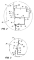
- Fig. 3 is an enlargement of a portion of the Fig. 1 drawing at a lower lubricant seal region illustrating structural details thereof.
- a hydrodynamic bearing unit 10 incorporating principles of the present invention includes a base 12 and a shaft 14 secured to the base 12 and extending upwardly therefrom in the orientation shown in Fig. 1.
- a rotating sleeve 16 fits snugly over the fixed shaft 14 with sufficient clearance between the shaft 14 and sleeve 16 to permit free relative rotation about a central axis of rotation 11.
- An annular thrust plate 18 is secured to the shaft 14 as by press-fitting or with a suitable adhesive.
- the thrust plate is seated against an annular shoulder 42 of the shaft 14 which defines a somewhat greater diameter below the shoulder 42 than above it, as shown in the Fig. 1 view.
- the thrust plate 18 defines two annular faces lying in planes perpendicular to the central axis 11.
- a thrust bushing 20 is secured to the sleeve 16 with a suitable adhesive 44 and overlies the thrust plate 18 to complete the hydrodynamic bearing unit.
- a suitable lubricant may then be introduced into the bearing unit by conventional techniques, such as vacuum loading.
- the shaft 14 and thrust plate 18 may be formed of hardened, tempered steel alloy, while the sleeve 16 and thrust bushing 20 may be formed of bronze, for example.
- a hollow cylindrical outer hub 26 is fitted over the sleeve 16 and supports one or more rotating data storage disks in a stacked arrangement extending upwardly from an integral lower flange 28.
- a spindle motor includes a fixed stator assembly 30, and a rotating annular magnet 32 closely facing outer pole faces of the stator assembly 30.
- An annular ferromagnetic ring 34 provides a flux return path to the alternating polar faces of the annular permanent magnet 32, and provides a magnetic shield to inhibit stray magnetic flux from the magnet 32 from reaching the data storage disks.
- the cylinder 16 includes at least one journal bearing 22, and Fig. 1 shows two journal bearings 22, a lower one of which is directly adjacent to sealing region at a lower end of the cylinder 16, and the other one of which is directly adjacent to a lower surface of the thrust bearing 18.
- the journal bearings may be patterned by suitable machining techniques to define pumping grooves forming herringbone or other pumping patterns which are operative to pump hydrodynamic lubricant incident to rotation of the sleeve 16 about the shaft 14.
- the sleeve 16 forms a gap adjacent to the shaft 14 throughout an inner longitudinal region 24 in order to define and provide a lubricant reservoir for supplying lubricant to the two axial bearing regions 22 during operation of the hydrodynamic bearing unit.
- the thrust plate 18 may be patterned by suitable machining techniques to define a pumping pattern, such as spiral grooves.
- the thrust bushing 20 is secured over the thrust plate 18 with sufficient clearance to permit free relative rotation between mating surfaces of the plate 18 and 20 forming an upper thrust bearing 60 and mating surfaces of the plate 18 and sleeve 16 forming a lower thrust bearing 62.
- the bearing surface clearances are selected to minimize axial runout while permitting free relative rotation.
- the present hydrodynamic bearing system includes a top seal 36 and a bottom seal 38.
- Each seal advantageously employs centrifugal force present during relative rotation between the shaft 14 and sleeve 16 as well as capillary force in order to confine the bearing lubricant inside of the bearing system.
- the top seal 36 includes a primary seal and a secondary seal.
- the primary seal is formed within a Vee-shaped gap 40 defined between mating faces of the thrust plate 18 and the thrust bushing 20 at a portion thereof radially inside of the upper thrust bearing 60.
- the thrust plate 18 and the thrust bushing 20 are preferably tapered prior to assembly to define angled regions defining the Vee-shaped gap 40 after bearing unit assembly.
- the Vee-shaped gap 40 has a base facing the shaft 14 and an apex converging toward the upper thrust bearing 60.
- the Vee-shaped gap 40 serves as a lubricant reservoir, and lubricant is maintained within the reservoir during non-operating intervals by surface tension (capillary force) and during operation by centrifugal force resulting from relative rotation between the shaft 14 and sleeve 16.
- the fixed shaft 14 has a step 42 onto which the lower face of the thrust plate 18 is registered.
- the presence of the step 42 makes the radial extent of the gap 40 longer at the upper thrust clearance than at the lower thrust clearance.
- the lubricant occupies the Vee-shaped gap 40 for about one half of the length thereof extending from the apex, as shown in Figs. 1 and 2.
- a secondary seal is also provided outside of the primary sealing gap 40 by an annular diverging gap 46 defined by a frustoconical surface 48 of the shaft 14 and by an adjacently facing frustoconical surface 47 of the thrust bushing 20.
- annular diverging gap 46 defined by a frustoconical surface 48 of the shaft 14 and by an adjacently facing frustoconical surface 47 of the thrust bushing 20.
- the frustoconical surface 48 of the shaft 14 forms an acute angle with the axis of rotation 11 of approximately 11 degrees
- the frustoconical surface 47 of the thrust bushing 20 forms an acute angle with the axis of rotation 11 of approximately 5 degrees, thereby defining the annular diverging gap 46.
- the gap 46 converges in a radially outward direction toward the Vee-shaped gap 40, so that any lubricant escaping from the Vee-shaped gap 40 will be drawn back into the gap 40 by centrifugal force during rotation of the bushing 20 relative to the shaft 14.
- the shaft 14 and the bushing 20 define cylindrical walls 49 outwardly beyond the diverging gap 46, and these walls 49 may be coated with a suitable lubricant repelling agent or barrier film 90.
- the diverging gap 46 and the barrier film 90 will attract lubricant otherwise escaping from the primary seal 40, and the centrifugal force provided by the inwardly tapered frustoconical sections 48 and 47 will tend to drive the lubricant back to the area of the primary seal 40.
- the shaft section facing the Vee-shaped groove 40 may be of constant diameter or may be a continuation of the frustoconical region 48.
- the combination of the constant diameter (or tapered) shaft region, the bushing boundary 70 of the Vee-shaped groove 40, and the frustoconical region 47 of the bushing at the two sides of a primary seal opening 41 at the throat of the diverging gap 46 increases the contact angle of the lubricant at the opening 41 and inhibits lubricant from migrating outside of the primary seal 40.
- a lubricant reservoir is defined in an annular space 64 between an endwall of the thrust plate 18 and a corresponding annular recess of the sleeve 16.
- a somewhat smaller annular space 66 is provided for lubricant just below the lower thrust bearing 62 at the vicinity of the shaft 14.
- the lubricant may be any suitable material.
- a hydrocarbon-based lubricating oil having a viscosity at room temperature of 20-30 centipoise (cp) is preferred.
- the bottom lubricant seal 38 by a gap 50 defined by divergently facing frustoconical surfaces 51 and 53 of the shaft 14 and sleeve 16, respectively.
- the surface 51 forms an angle with the axis of rotation 11 of approximately 18 degrees
- the surface 53 forms an angle with the axis of rotation 11 of approximately 9.5 degrees.
- the divergent annular gap 50 has a throat region 56 lying immediately adjacent to an expansion region 54, such as a Vee-groove, containing lubricant and forming a lubricant reservoir.
- the throat region 56 is at a greater radius than a constant diameter region 52 at the divergent open end of the gap 50, so that centrifugal force resulting from rotation of the sleeve 16 relative to the fixed shaft 14 will tend to return lubricant to the reservoir region 54.
- capillary force maintains the lubricant within either the reservoir region 54 or the gap 50.
- the diverging gap 50 exerts both centrifugal and capillary forces on the lubricant in order to pump it back into the lower journal bearing 22.
- the lubricating liquid film extends approximately half of the axial distance into the Vee-groove 54 if it is present, and otherwise extends to about half of the axial distance into the bottom seal gap 50 (if the Vee-groove reservoir 54 is not present).
- a barrier film 90 may be coated onto constant-radius surfaces 52 of the lower seal 38 in the same manner and for the same reason as obtains for the barrier film 90 used in the top seal 36.
- the barrier film 90 is selected to repel the lubricant material. NyebarTM barrier film material is one suitable choice.
- the top primary seal 40 provides an extra centrifugal force toward the outside diameter of the thrust plate 18 when the sealing area is occupied by lubricant during dynamic events such as a shock load, thermal expansion, or bearing start/stop operations.
- the extra space within the primary seal 40 is provided by the presence of the step 42 on the shaft 14 on which the thrust plate 18 is fitted.
- the increase of the contact angle provided by the taper sections on the shaft 14 and the thrust bushing 20 at the primary seal opening 41 prevents the lubricant from migrating out of the primary sealing area.
- top secondary seal attracts any splashed or wandering lubricant droplets by capillary force and by the presence of the barrier film, during static conditions, and drives the lubricant back to the primary seal gap 40 by rotation-induced centrifugal force and the inwardly tapered seal boundary surfaces 47 and 48.
- the bottom seal which consists of a diverging gap 50 with inwardly tapered boundaries similarly prevents lubricant from escaping the bearing by inducing both capillary forces and centrifugal forces toward the lower journal bearing 22.
- the Vee-groove 54 When the Vee-groove 54 is provided, the lower lubricant surface will remain inside of the Vee-groove during normal operation. The increase in contact angle of the lubricant at the lower end of the Vee-groove 54 will discourage migration of the lubricant outside of the bearing structure.
- the bearing unit may be readily assembled using conventional assembly techniques and achieves a low-cost, reliable solution for a self-lubricated, dual action radial and axial hydrodynamic bearing system manifesting superior retention of lubricant at rest, during operation, and in response to shock forces.
Landscapes
- Engineering & Computer Science (AREA)
- General Engineering & Computer Science (AREA)
- Mechanical Engineering (AREA)
- Chemical & Material Sciences (AREA)
- Oil, Petroleum & Natural Gas (AREA)
- Sliding-Contact Bearings (AREA)
- Sealing Of Bearings (AREA)
- Rotational Drive Of Disk (AREA)
Applications Claiming Priority (2)
| Application Number | Priority Date | Filing Date | Title |
|---|---|---|---|
| US08/308,078 US5423612A (en) | 1994-09-16 | 1994-09-16 | Hydrodynamic bearing and seal |
| US308078 | 1994-09-16 |
Publications (3)
| Publication Number | Publication Date |
|---|---|
| EP0702163A2 true EP0702163A2 (fr) | 1996-03-20 |
| EP0702163A3 EP0702163A3 (fr) | 1996-05-15 |
| EP0702163B1 EP0702163B1 (fr) | 1999-11-24 |
Family
ID=23192452
Family Applications (1)
| Application Number | Title | Priority Date | Filing Date |
|---|---|---|---|
| EP95306203A Expired - Lifetime EP0702163B1 (fr) | 1994-09-16 | 1995-09-05 | Palier hydrodynamique et étanchéité |
Country Status (5)
| Country | Link |
|---|---|
| US (1) | US5423612A (fr) |
| EP (1) | EP0702163B1 (fr) |
| JP (1) | JPH08105446A (fr) |
| KR (1) | KR960011183A (fr) |
| DE (1) | DE69513473T2 (fr) |
Families Citing this family (64)
| Publication number | Priority date | Publication date | Assignee | Title |
|---|---|---|---|---|
| US5558443A (en) * | 1994-07-22 | 1996-09-24 | Quantum Corporation | Shaft seal for hydrodynamic bearing unit |
| US5667309A (en) * | 1994-11-15 | 1997-09-16 | Sankyo Seiki Mfg. Co., Ltd. | Bearing seal system |
| US5956204A (en) * | 1995-02-13 | 1999-09-21 | Seagate Technology, Inc. | Magnetic disc drive having magnetic particle trap for hydrodynamic bearing |
| US5969903A (en) * | 1995-02-13 | 1999-10-19 | Seagate Technology, Inc. | Magnetic particle trap for hydrodynamic bearing |
| US5533811A (en) * | 1995-02-14 | 1996-07-09 | Quantum Corporation | Hydrodynamic bearing having inverted surface tension seals |
| US5590003A (en) * | 1995-03-08 | 1996-12-31 | Seagate Technology, Inc. | Hydrodynamic spindle motor having distributed windings |
| US5770906A (en) * | 1995-06-13 | 1998-06-23 | Sae Magnetics (H.K.) Ltd. | Compact electric motor construction employing fluid bearings |
| JPH0932850A (ja) * | 1995-07-20 | 1997-02-04 | Koyo Seiko Co Ltd | 動圧軸受装置 |
| JPH0963245A (ja) * | 1995-08-24 | 1997-03-07 | Hitachi Ltd | 磁気ディスク装置 |
| US5634724A (en) * | 1995-08-25 | 1997-06-03 | Quantum Corporation | Hydrodynamic bearing for spindle motor having high inertial load |
| US5876124A (en) * | 1995-08-25 | 1999-03-02 | Quantum Corporation | Hydrodynamic bearing unit |
| US5516212A (en) * | 1995-09-18 | 1996-05-14 | Western Digital Corporation | Hydrodynamic bearing with controlled lubricant pressure distribution |
| JP3933692B2 (ja) * | 1995-12-22 | 2007-06-20 | コーニンクレッカ フィリップス エレクトロニクス エヌ ヴィ | V字状オイルバリヤ溝を有する動力学的溝軸受 |
| US5806987A (en) * | 1996-02-07 | 1998-09-15 | Sankyo Seiki Mfg. Co., Ltd. | Hydrodynamic bearing apparatus |
| JPH09222121A (ja) * | 1996-02-16 | 1997-08-26 | Sankyo Seiki Mfg Co Ltd | 動圧軸受装置 |
| US5839833A (en) * | 1996-03-26 | 1998-11-24 | Quantum Corporation | Hydrodynamic bearing having lubricant particle traps |
| JP3395524B2 (ja) * | 1996-06-10 | 2003-04-14 | 松下電器産業株式会社 | 縦型流体軸受装置 |
| US5768056A (en) * | 1996-08-07 | 1998-06-16 | Seagate Technology, Inc. | Reduction of liquid and smear collection/pickup by sliders |
| US5714817A (en) * | 1996-09-13 | 1998-02-03 | Synektron Corporation | Labyrinth seal system |
| JP3544098B2 (ja) * | 1997-05-19 | 2004-07-21 | 日本電産株式会社 | 動圧流体軸受装置 |
| JP3811553B2 (ja) * | 1997-09-05 | 2006-08-23 | 株式会社ジェイテクト | 流体軸受 |
| US5920443A (en) * | 1997-09-15 | 1999-07-06 | Ekhoff; Donald L. | Disk drive assembly and method having direct aerodynamic disk support |
| US6154339A (en) * | 1997-11-06 | 2000-11-28 | Seagate Technology Llc. | Centrifugal capillary seal for use with fluid dynamic bearings |
| JP3846034B2 (ja) * | 1997-11-20 | 2006-11-15 | 株式会社デンソー | 軸受け |
| US6196722B1 (en) * | 1998-01-13 | 2001-03-06 | Matsushita Electric Industrial Co., Ltd. | Hydrodynamic bearing |
| US6055126A (en) | 1998-07-06 | 2000-04-25 | Seagate Technology, Inc. | Disc drive having hydrodynamic labyrinth seal and magnet shield |
| US6095302A (en) * | 1999-03-31 | 2000-08-01 | China Hua Yang Rolling Bearing Co. | One way clutch bearing |
| JP2001082458A (ja) * | 1999-09-08 | 2001-03-27 | Koyo Seiko Co Ltd | 動圧軸受 |
| JP4248176B2 (ja) * | 2001-12-14 | 2009-04-02 | 株式会社ジェイテクト | 動圧軸受 |
| US20030190100A1 (en) * | 2002-04-05 | 2003-10-09 | Grantz Alan L. | Radial capillary seal for fluid dynamic bearing motors |
| JP3828452B2 (ja) * | 2002-04-18 | 2006-10-04 | 日本電産株式会社 | スピンドルモータ及びこのスピンドルモータを用いたディスク駆動装置 |
| US6669369B1 (en) | 2002-06-21 | 2003-12-30 | Seagate Technology Llc | Fluid dynamic bearing secondary capillary seal reservoir |
| US7063462B2 (en) * | 2002-08-19 | 2006-06-20 | Seagate Technology Llc | Asymmetry pressure regulation and check valve device for fluid dynamic bearing |
| CN100545930C (zh) * | 2002-09-30 | 2009-09-30 | 希捷科技有限公司 | 带有轨道环的流体动力轴承 |
| US6991376B2 (en) * | 2002-11-05 | 2006-01-31 | Seagate Technology Llc | Low profile fluid dynamic bearing motor having increased journal span |
| US7239477B2 (en) * | 2002-11-05 | 2007-07-03 | Seagate Technology Llc | Low profile air-oil hybrid fluid dynamic bearing motor |
| US7134792B2 (en) * | 2002-11-05 | 2006-11-14 | Seagate Technology Llc | Single thrust-journal bearing cup fluid dynamic bearing motor |
| US7073945B2 (en) * | 2002-11-05 | 2006-07-11 | Seagate Technology Llc | Dynamic radial capillary seal |
| US7455456B2 (en) | 2003-01-10 | 2008-11-25 | Sony Corporation | Bearing unit and rotation drive device using the same |
| US6814492B2 (en) * | 2003-01-30 | 2004-11-09 | Minebea Co., Ltd. | Fluid trap for oil migration prevention |
| JP4056416B2 (ja) * | 2003-03-24 | 2008-03-05 | 日本電産株式会社 | 動圧軸受及びこれを用いたスピンドルモータ並びにこのスピンドルモータを備えたディスク駆動装置 |
| US7493695B2 (en) * | 2003-04-18 | 2009-02-24 | Seagate Technology Llc | Method for designing a fluid dynamic bearing system |
| US20050056303A1 (en) * | 2003-09-16 | 2005-03-17 | Wei-Ming Lee | Oblique burnish/wipe mechanism for hard drive disk like media |
| US7001074B2 (en) * | 2003-04-21 | 2006-02-21 | Seagate Technology Llc | High pressure barrier to oil loss by diffusion |
| US7234868B2 (en) * | 2003-05-07 | 2007-06-26 | Seagate Technology Llc | Radial pumping oil seal for fluid dynamic bearing motor |
| JP4084843B2 (ja) * | 2003-06-12 | 2008-04-30 | 日本電産株式会社 | 動圧軸受装置およびその製造方法 |
| JP2005155689A (ja) * | 2003-11-21 | 2005-06-16 | Matsushita Electric Ind Co Ltd | 流体軸受装置 |
| JP4446727B2 (ja) * | 2003-12-17 | 2010-04-07 | Ntn株式会社 | 流体軸受装置 |
| US7040575B2 (en) * | 2004-03-29 | 2006-05-09 | The Boeing Company | Foam composite insulation for aircraft |
| US7422371B2 (en) * | 2005-02-09 | 2008-09-09 | Seagate Technology Llc | Active hybrid FDB motor |
| US7956499B2 (en) * | 2005-06-02 | 2011-06-07 | Seagate Technology Llc | Motor magnetic force attenuator |
| US8562222B2 (en) * | 2005-06-24 | 2013-10-22 | Seagate Technology Llc | Hub and spindle assembly |
| JP4943758B2 (ja) * | 2005-09-27 | 2012-05-30 | アルファナテクノロジー株式会社 | 流体軸受装置 |
| JP5139572B2 (ja) * | 2005-09-27 | 2013-02-06 | アルファナテクノロジー株式会社 | 流体軸受装置及び流体軸受装置を有するディスク駆動用モータ |
| US7679243B2 (en) * | 2005-12-22 | 2010-03-16 | Seagate Technology Llc | Motor assembly with multifunctional components |
| JP2007170641A (ja) * | 2005-12-26 | 2007-07-05 | Matsushita Electric Ind Co Ltd | 流体軸受装置およびその製造方法、スピンドルモータおよび記録再生装置 |
| US7843664B2 (en) * | 2006-02-09 | 2010-11-30 | Seagate Technology Llc | Electrostatic discharge apparatus for hub and spindle assemblies |
| WO2007108361A1 (fr) * | 2006-03-20 | 2007-09-27 | Ntn Corporation | Palier fluide |
| DE102006020408B4 (de) * | 2006-05-03 | 2019-10-31 | Minebea Mitsumi Inc. | Dichtungsanordnung für ein Fluidlager |
| US8454238B2 (en) * | 2006-08-23 | 2013-06-04 | Seagate Technology Llc | Spindle regions |
| JP2007309528A (ja) * | 2007-08-30 | 2007-11-29 | Seiko Instruments Inc | 流体動圧軸受 |
| KR101119350B1 (ko) * | 2010-05-17 | 2012-03-06 | 삼성전기주식회사 | 스핀들모터 |
| JP2013172569A (ja) * | 2012-02-21 | 2013-09-02 | Samsung Electromechanics Japan Advanced Technology Co Ltd | 回転機器 |
| DE102012025753B4 (de) | 2012-08-16 | 2026-04-30 | Minebea Mitsumi Inc. | Spindelmotor mit niedriger Bauhöhe |
Family Cites Families (13)
| Publication number | Priority date | Publication date | Assignee | Title |
|---|---|---|---|---|
| US3325231A (en) * | 1963-10-10 | 1967-06-13 | Webcor Inc | Miniature motor bearing |
| US3778123A (en) * | 1971-11-17 | 1973-12-11 | Singer Co | Liquid bearing unit and seal |
| US4496474A (en) * | 1982-12-20 | 1985-01-29 | Akzona Incorporated | Asphalt emulsions comprising N-aliphatic-1,3-diaminopentane emulsifier and process |
| NL8303833A (nl) * | 1983-11-08 | 1985-06-03 | Philips Nv | Spiraalgroeflager met metaalsmering en antibevochtigingslaag. |
| US4726693A (en) * | 1984-10-05 | 1988-02-23 | Hewlett-Packard Company | Precision hydrodynamic bearing |
| US5112142A (en) * | 1987-08-12 | 1992-05-12 | Digital Equipment Corporation | Hydrodynamic bearing |
| US4795275A (en) * | 1987-08-12 | 1989-01-03 | Digital Equipment Corporation | Hydrodynamic bearing |
| JP2506836B2 (ja) * | 1987-11-02 | 1996-06-12 | 松下電器産業株式会社 | 動圧型流体軸受装置 |
| JPH0335469A (ja) * | 1989-06-30 | 1991-02-15 | Matsushita Electric Ind Co Ltd | ディスク駆動装置 |
| US5067528A (en) * | 1989-07-19 | 1991-11-26 | Digital Equipment Corporation | Hydrodynamic bearing |
| JP2903664B2 (ja) * | 1990-07-17 | 1999-06-07 | 松下電器産業株式会社 | モータの軸受装置 |
| US5246294A (en) * | 1991-05-30 | 1993-09-21 | Digital Equipment Corporation | Flow-regulating hydrodynamic bearing |
| US5427456A (en) * | 1994-04-12 | 1995-06-27 | Synektron Corporation | Fluid bearing with asymmetrical groove pattern |
-
1994
- 1994-09-16 US US08/308,078 patent/US5423612A/en not_active Expired - Lifetime
-
1995
- 1995-09-05 DE DE69513473T patent/DE69513473T2/de not_active Expired - Lifetime
- 1995-09-05 EP EP95306203A patent/EP0702163B1/fr not_active Expired - Lifetime
- 1995-09-14 JP JP7236594A patent/JPH08105446A/ja active Pending
- 1995-09-15 KR KR1019950030198A patent/KR960011183A/ko not_active Withdrawn
Also Published As
| Publication number | Publication date |
|---|---|
| EP0702163B1 (fr) | 1999-11-24 |
| JPH08105446A (ja) | 1996-04-23 |
| DE69513473D1 (de) | 1999-12-30 |
| KR960011183A (ko) | 1996-04-20 |
| US5423612A (en) | 1995-06-13 |
| EP0702163A3 (fr) | 1996-05-15 |
| DE69513473T2 (de) | 2000-08-03 |
Similar Documents
| Publication | Publication Date | Title |
|---|---|---|
| US5423612A (en) | Hydrodynamic bearing and seal | |
| US5634724A (en) | Hydrodynamic bearing for spindle motor having high inertial load | |
| US5558443A (en) | Shaft seal for hydrodynamic bearing unit | |
| JP3578948B2 (ja) | モータ | |
| US5876124A (en) | Hydrodynamic bearing unit | |
| US5558445A (en) | Self-contained hydrodynamic bearing unit and seals | |
| US7239477B2 (en) | Low profile air-oil hybrid fluid dynamic bearing motor | |
| US5969448A (en) | Electric spindle motor | |
| US5658080A (en) | Motor with a hydro-dynamic bearing | |
| JP2004019705A (ja) | スピンドルモータ及びこれを備えたディスク駆動装置 | |
| US20060002641A1 (en) | Fixed shaft type fluid dynamic bearing motor | |
| US5839833A (en) | Hydrodynamic bearing having lubricant particle traps | |
| CN1128940C (zh) | 具有多个止推板的两端开口的流体动力轴承 | |
| JP3234030B2 (ja) | スピンドルモータ | |
| EP0697535A2 (fr) | Unité de palier hydrodynamique | |
| JP3799176B2 (ja) | 動圧型焼結含油軸受ユニット | |
| JP3549367B2 (ja) | 動圧流体軸受装置及び電動機 | |
| JP4202080B2 (ja) | 動圧軸受装置及びこれを用いたスピンドルモータ | |
| KR100453332B1 (ko) | 유체동압 베어링 모터 | |
| JP3828464B2 (ja) | スピンドルモータ及びこれを備えたディスク駆動装置 | |
| JPH10255389A (ja) | 光学ディスク回転装置 | |
| JPH03260415A (ja) | 動圧流体軸受装置 | |
| KR100430426B1 (ko) | 모터구조체 | |
| JP2006071087A (ja) | 軸固定型動圧流体軸受モータ及び薄型記録ディスク装置 | |
| JP3135684B2 (ja) | スピンドルモータ |
Legal Events
| Date | Code | Title | Description |
|---|---|---|---|
| PUAI | Public reference made under article 153(3) epc to a published international application that has entered the european phase |
Free format text: ORIGINAL CODE: 0009012 |
|
| AK | Designated contracting states |
Kind code of ref document: A2 Designated state(s): DE FR GB IT NL |
|
| PUAL | Search report despatched |
Free format text: ORIGINAL CODE: 0009013 |
|
| RHK1 | Main classification (correction) |
Ipc: F16C 33/10 |
|
| AK | Designated contracting states |
Kind code of ref document: A3 Designated state(s): DE FR GB IT NL |
|
| 17P | Request for examination filed |
Effective date: 19961106 |
|
| 17Q | First examination report despatched |
Effective date: 19981117 |
|
| GRAG | Despatch of communication of intention to grant |
Free format text: ORIGINAL CODE: EPIDOS AGRA |
|
| GRAG | Despatch of communication of intention to grant |
Free format text: ORIGINAL CODE: EPIDOS AGRA |
|
| GRAH | Despatch of communication of intention to grant a patent |
Free format text: ORIGINAL CODE: EPIDOS IGRA |
|
| GRAH | Despatch of communication of intention to grant a patent |
Free format text: ORIGINAL CODE: EPIDOS IGRA |
|
| GRAA | (expected) grant |
Free format text: ORIGINAL CODE: 0009210 |
|
| AK | Designated contracting states |
Kind code of ref document: B1 Designated state(s): DE FR GB IT NL |
|
| PG25 | Lapsed in a contracting state [announced via postgrant information from national office to epo] |
Ref country code: NL Free format text: LAPSE BECAUSE OF FAILURE TO SUBMIT A TRANSLATION OF THE DESCRIPTION OR TO PAY THE FEE WITHIN THE PRESCRIBED TIME-LIMIT Effective date: 19991124 Ref country code: IT Free format text: LAPSE BECAUSE OF FAILURE TO SUBMIT A TRANSLATION OF THE DESCRIPTION OR TO PAY THE FEE WITHIN THE PRESCRIBED TIME-LIMIT;WARNING: LAPSES OF ITALIAN PATENTS WITH EFFECTIVE DATE BEFORE 2007 MAY HAVE OCCURRED AT ANY TIME BEFORE 2007. THE CORRECT EFFECTIVE DATE MAY BE DIFFERENT FROM THE ONE RECORDED. Effective date: 19991124 Ref country code: FR Free format text: LAPSE BECAUSE OF FAILURE TO SUBMIT A TRANSLATION OF THE DESCRIPTION OR TO PAY THE FEE WITHIN THE PRESCRIBED TIME-LIMIT Effective date: 19991124 |
|
| REF | Corresponds to: |
Ref document number: 69513473 Country of ref document: DE Date of ref document: 19991230 |
|
| EN | Fr: translation not filed | ||
| NLV1 | Nl: lapsed or annulled due to failure to fulfill the requirements of art. 29p and 29m of the patents act | ||
| PLBE | No opposition filed within time limit |
Free format text: ORIGINAL CODE: 0009261 |
|
| STAA | Information on the status of an ep patent application or granted ep patent |
Free format text: STATUS: NO OPPOSITION FILED WITHIN TIME LIMIT |
|
| 26N | No opposition filed | ||
| REG | Reference to a national code |
Ref country code: GB Ref legal event code: IF02 |
|
| REG | Reference to a national code |
Ref country code: GB Ref legal event code: 732E Free format text: REGISTERED BETWEEN 20090716 AND 20090722 |
|
| REG | Reference to a national code |
Ref country code: FR Ref legal event code: TP |
|
| PGFP | Annual fee paid to national office [announced via postgrant information from national office to epo] |
Ref country code: GB Payment date: 20140929 Year of fee payment: 20 |
|
| PGFP | Annual fee paid to national office [announced via postgrant information from national office to epo] |
Ref country code: DE Payment date: 20140929 Year of fee payment: 20 |
|
| REG | Reference to a national code |
Ref country code: DE Ref legal event code: R071 Ref document number: 69513473 Country of ref document: DE |
|
| REG | Reference to a national code |
Ref country code: GB Ref legal event code: PE20 Expiry date: 20150904 |
|
| PG25 | Lapsed in a contracting state [announced via postgrant information from national office to epo] |
Ref country code: GB Free format text: LAPSE BECAUSE OF EXPIRATION OF PROTECTION Effective date: 20150904 |