EP0702170A2 - Wiedereinkupplungssteuerung - Google Patents
Wiedereinkupplungssteuerung Download PDFInfo
- Publication number
- EP0702170A2 EP0702170A2 EP95114097A EP95114097A EP0702170A2 EP 0702170 A2 EP0702170 A2 EP 0702170A2 EP 95114097 A EP95114097 A EP 95114097A EP 95114097 A EP95114097 A EP 95114097A EP 0702170 A2 EP0702170 A2 EP 0702170A2
- Authority
- EP
- European Patent Office
- Prior art keywords
- rate
- throttle
- clutch
- reengagement
- nominal
- Prior art date
- Legal status (The legal status is an assumption and is not a legal conclusion. Google has not performed a legal analysis and makes no representation as to the accuracy of the status listed.)
- Granted
Links
- 230000009347 mechanical transmission Effects 0.000 claims abstract description 21
- 230000005540 biological transmission Effects 0.000 claims description 32
- 238000000034 method Methods 0.000 claims description 31
- 230000008859 change Effects 0.000 claims description 14
- 239000000446 fuel Substances 0.000 claims description 10
- 238000012545 processing Methods 0.000 claims description 10
- 238000006073 displacement reaction Methods 0.000 claims description 9
- 230000004044 response Effects 0.000 claims description 5
- 238000004891 communication Methods 0.000 claims description 2
- 230000001133 acceleration Effects 0.000 abstract description 5
- 238000012546 transfer Methods 0.000 description 5
- 230000007935 neutral effect Effects 0.000 description 4
- 230000001360 synchronised effect Effects 0.000 description 4
- 230000003247 decreasing effect Effects 0.000 description 2
- 230000000994 depressogenic effect Effects 0.000 description 2
- 230000008569 process Effects 0.000 description 2
- 101100219315 Arabidopsis thaliana CYP83A1 gene Proteins 0.000 description 1
- 101000806846 Homo sapiens DNA-(apurinic or apyrimidinic site) endonuclease Proteins 0.000 description 1
- 101000835083 Homo sapiens Tissue factor pathway inhibitor 2 Proteins 0.000 description 1
- 101100269674 Mus musculus Alyref2 gene Proteins 0.000 description 1
- 101100140580 Saccharomyces cerevisiae (strain ATCC 204508 / S288c) REF2 gene Proteins 0.000 description 1
- 102100026134 Tissue factor pathway inhibitor 2 Human genes 0.000 description 1
- 238000010276 construction Methods 0.000 description 1
- 238000011217 control strategy Methods 0.000 description 1
- 230000008878 coupling Effects 0.000 description 1
- 238000010168 coupling process Methods 0.000 description 1
- 238000005859 coupling reaction Methods 0.000 description 1
- 238000001914 filtration Methods 0.000 description 1
- 239000012530 fluid Substances 0.000 description 1
- 230000008676 import Effects 0.000 description 1
- 238000012986 modification Methods 0.000 description 1
- 230000004048 modification Effects 0.000 description 1
- 230000002441 reversible effect Effects 0.000 description 1
Images


Classifications
-
- B—PERFORMING OPERATIONS; TRANSPORTING
- B60—VEHICLES IN GENERAL
- B60W—CONJOINT CONTROL OF VEHICLE SUB-UNITS OF DIFFERENT TYPE OR DIFFERENT FUNCTION; CONTROL SYSTEMS SPECIALLY ADAPTED FOR HYBRID VEHICLES; ROAD VEHICLE DRIVE CONTROL SYSTEMS FOR PURPOSES NOT RELATED TO THE CONTROL OF A PARTICULAR SUB-UNIT
- B60W30/00—Purposes of road vehicle drive control systems not related to the control of a particular sub-unit, e.g. of systems using conjoint control of vehicle sub-units
- B60W30/18—Propelling the vehicle
-
- B—PERFORMING OPERATIONS; TRANSPORTING
- B60—VEHICLES IN GENERAL
- B60W—CONJOINT CONTROL OF VEHICLE SUB-UNITS OF DIFFERENT TYPE OR DIFFERENT FUNCTION; CONTROL SYSTEMS SPECIALLY ADAPTED FOR HYBRID VEHICLES; ROAD VEHICLE DRIVE CONTROL SYSTEMS FOR PURPOSES NOT RELATED TO THE CONTROL OF A PARTICULAR SUB-UNIT
- B60W10/00—Conjoint control of vehicle sub-units of different type or different function
- B60W10/02—Conjoint control of vehicle sub-units of different type or different function including control of driveline clutches
-
- B—PERFORMING OPERATIONS; TRANSPORTING
- B60—VEHICLES IN GENERAL
- B60W—CONJOINT CONTROL OF VEHICLE SUB-UNITS OF DIFFERENT TYPE OR DIFFERENT FUNCTION; CONTROL SYSTEMS SPECIALLY ADAPTED FOR HYBRID VEHICLES; ROAD VEHICLE DRIVE CONTROL SYSTEMS FOR PURPOSES NOT RELATED TO THE CONTROL OF A PARTICULAR SUB-UNIT
- B60W10/00—Conjoint control of vehicle sub-units of different type or different function
- B60W10/04—Conjoint control of vehicle sub-units of different type or different function including control of propulsion units
- B60W10/06—Conjoint control of vehicle sub-units of different type or different function including control of propulsion units including control of combustion engines
-
- B—PERFORMING OPERATIONS; TRANSPORTING
- B60—VEHICLES IN GENERAL
- B60W—CONJOINT CONTROL OF VEHICLE SUB-UNITS OF DIFFERENT TYPE OR DIFFERENT FUNCTION; CONTROL SYSTEMS SPECIALLY ADAPTED FOR HYBRID VEHICLES; ROAD VEHICLE DRIVE CONTROL SYSTEMS FOR PURPOSES NOT RELATED TO THE CONTROL OF A PARTICULAR SUB-UNIT
- B60W10/00—Conjoint control of vehicle sub-units of different type or different function
- B60W10/10—Conjoint control of vehicle sub-units of different type or different function including control of change-speed gearings
- B60W10/11—Stepped gearings
-
- B—PERFORMING OPERATIONS; TRANSPORTING
- B60—VEHICLES IN GENERAL
- B60W—CONJOINT CONTROL OF VEHICLE SUB-UNITS OF DIFFERENT TYPE OR DIFFERENT FUNCTION; CONTROL SYSTEMS SPECIALLY ADAPTED FOR HYBRID VEHICLES; ROAD VEHICLE DRIVE CONTROL SYSTEMS FOR PURPOSES NOT RELATED TO THE CONTROL OF A PARTICULAR SUB-UNIT
- B60W30/00—Purposes of road vehicle drive control systems not related to the control of a particular sub-unit, e.g. of systems using conjoint control of vehicle sub-units
- B60W30/18—Propelling the vehicle
- B60W30/1819—Propulsion control with control means using analogue circuits, relays or mechanical links
-
- B—PERFORMING OPERATIONS; TRANSPORTING
- B60—VEHICLES IN GENERAL
- B60W—CONJOINT CONTROL OF VEHICLE SUB-UNITS OF DIFFERENT TYPE OR DIFFERENT FUNCTION; CONTROL SYSTEMS SPECIALLY ADAPTED FOR HYBRID VEHICLES; ROAD VEHICLE DRIVE CONTROL SYSTEMS FOR PURPOSES NOT RELATED TO THE CONTROL OF A PARTICULAR SUB-UNIT
- B60W50/00—Details of control systems for road vehicle drive control not related to the control of a particular sub-unit, e.g. process diagnostic or vehicle driver interfaces
- B60W2050/0001—Details of the control system
- B60W2050/0019—Control system elements or transfer functions
- B60W2050/0042—Transfer function lag; delays
-
- B—PERFORMING OPERATIONS; TRANSPORTING
- B60—VEHICLES IN GENERAL
- B60W—CONJOINT CONTROL OF VEHICLE SUB-UNITS OF DIFFERENT TYPE OR DIFFERENT FUNCTION; CONTROL SYSTEMS SPECIALLY ADAPTED FOR HYBRID VEHICLES; ROAD VEHICLE DRIVE CONTROL SYSTEMS FOR PURPOSES NOT RELATED TO THE CONTROL OF A PARTICULAR SUB-UNIT
- B60W2510/00—Input parameters relating to a particular sub-units
- B60W2510/06—Combustion engines, Gas turbines
- B60W2510/0604—Throttle position
-
- B—PERFORMING OPERATIONS; TRANSPORTING
- B60—VEHICLES IN GENERAL
- B60W—CONJOINT CONTROL OF VEHICLE SUB-UNITS OF DIFFERENT TYPE OR DIFFERENT FUNCTION; CONTROL SYSTEMS SPECIALLY ADAPTED FOR HYBRID VEHICLES; ROAD VEHICLE DRIVE CONTROL SYSTEMS FOR PURPOSES NOT RELATED TO THE CONTROL OF A PARTICULAR SUB-UNIT
- B60W2510/00—Input parameters relating to a particular sub-units
- B60W2510/06—Combustion engines, Gas turbines
- B60W2510/0638—Engine speed
- B60W2510/0652—Speed change rate
-
- B—PERFORMING OPERATIONS; TRANSPORTING
- B60—VEHICLES IN GENERAL
- B60W—CONJOINT CONTROL OF VEHICLE SUB-UNITS OF DIFFERENT TYPE OR DIFFERENT FUNCTION; CONTROL SYSTEMS SPECIALLY ADAPTED FOR HYBRID VEHICLES; ROAD VEHICLE DRIVE CONTROL SYSTEMS FOR PURPOSES NOT RELATED TO THE CONTROL OF A PARTICULAR SUB-UNIT
- B60W2540/00—Input parameters relating to occupants
- B60W2540/12—Brake pedal position
-
- B—PERFORMING OPERATIONS; TRANSPORTING
- B60—VEHICLES IN GENERAL
- B60W—CONJOINT CONTROL OF VEHICLE SUB-UNITS OF DIFFERENT TYPE OR DIFFERENT FUNCTION; CONTROL SYSTEMS SPECIALLY ADAPTED FOR HYBRID VEHICLES; ROAD VEHICLE DRIVE CONTROL SYSTEMS FOR PURPOSES NOT RELATED TO THE CONTROL OF A PARTICULAR SUB-UNIT
- B60W2710/00—Output or target parameters relating to a particular sub-units
- B60W2710/02—Clutches
- B60W2710/021—Clutch engagement state
- B60W2710/023—Clutch engagement rate
Definitions
- the present invention relates to a master clutch reengagement control for an automated mechanical transmission system of the type having a clutch actuator operated by the system controller.
- the present invention relates to a master clutch control for controlling the rate of reengagement of a vehicular automated mechanical transmission system master clutch upon completion of a downshift.
- Controls for controlling the rate of engaging the vehicle master clutch, both for start-from-stop and for dynamic shifting, are well known in the prior art. Typically, the controls involved a rapid movement to the "touch point” or point of "incipient engagement,” and then a modulated continuing engagement thereafter. Examples of such controls may be seen by reference to U.S. Patents No. 4,081,065; 4,638,898; 4,646,891; 4,766,967; 5,184,301; 5,316,116 and 5,335,174, the disclosures of which are incorporated herein by reference.
- the slip i.e., ES - IS
- the drawbacks of the prior art are minimized or overcome by the provision of a master clutch reengagement control which senses braking and/or coasting downshift conditions and, in response thereto, modifies the rate of master clutch reengagement after engagement of the target gear ratio to provide smoother, less harsh shifts.
- CLU_RATE nominal clutch reengagement rate
- Figure 1 is a schematic illustration of an automated mechanical transmission system of the type particularly well suited to be controlled by the method/apparatus of the present invention.
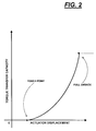
- Figure 2 is a graphical representation of the relationship between torque transfer capacity and actuator displacement.
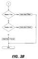
- Figures 3A and 3B are graphical representations, in flow chart format, of the control method/apparatus of the present invention.
- downshift shall mean shifting from a higher-speed gear ratio into a lower-speed gear ratio and shall include single as well as skip downshifts.
- FIG. 1 schematically illustrates a vehicular automated mechanical transmission system 10 including an automated multi-speed change gear transmission 12 driven by a fuel controlled engine 14, such as a well-known diesel engine, through a coupling such as master friction clutch 16.
- the output of automated transmission 12 is output shaft 18 which is adapted for driving connection to an appropriate vehicle component such as the differential of a drive axle, a transfer case, or the like, as is well known in the prior art.
- crank shaft 20 of engine 14 will drive the driving plates 22 of master friction clutch 16 which are frictionally engageable to driven plates 24 for driving the input shaft 26 of transmission 12.
- the above-mentioned power train components are acted upon and/or monitored by several devices, each of which will be discussed briefly below. These devices will include a throttle pedal position or throttle opening monitor assembly 28 which senses the operator set position of the operator controlled throttle device 30, a fuel control device 32 for controlling the amount of fuel to be supplied to engine 14, and engine speed sensor 34 which senses the rotational speed of the engine, a clutch operator 36 which engages and disengages master clutch 16 and which may also provide information as to the status of the clutch, an input shaft speed sensor 38 for sensing the rotational speed of transmission input shaft 26, a transmission operator 40 which is effective to shift the transmission 12 into a selected gear ratio and to provide a signal indicative of the gear neutral condition and/or the currently engaged gear ratio, and an output shaft speed sensor 42 for sensing the rotational speed of the output shaft 18.
- a throttle pedal position or throttle opening monitor assembly 28 which senses the operator set position of the operator controlled throttle device 30, a fuel control device 32 for controlling the amount of fuel to be supplied to engine 14, and engine speed sensor 34 which senses the
- the engine fuel control device 32 may include an electronic computer-based engine controller 32A and/or an electronic data link of the type conforming to the SAE J1922, SAE J1939 and/or ISO 11898 protocols.
- a sensor 43 is also provided for sensing operation of the vehicle brake system.
- the above-mentioned devices supply information to and/or accept commands from the central processing unit or control 44.
- the central processing unit 44 may include analog and/or digital electronic calculation and logic circuitry as is known in the prior art.
- the central processing unit 44 will also receive information from a shift control assembly 46 by which the vehicle operator may select a reverse (R) neutral (N) or forward drive (D) mode of operation of the vehicle.
- An electrical power source (not shown) and/or a source of pressurized fluid (not shown) provides electrical and/or pneumatic and/or hydraulic power to the various sensing, operating and/or processing units.
- the central processing unit 44 may be provided with circuitry for differentiating the input signal from at least sensors 34 and 38 to provide a calculated signal indicative of the acceleration and/or deceleration of the engine and the transmission input shaft 26.
- the CPU 44 may also be provided with circuitry and/or logic rules to compare the input signals of sensors 38 and 42 to verify and identify that the transmission 12 is engaged in a particular gear ratio, etc.
- shifts usually are implemented using the double-clutching technique.
- a target engine speed was calculated as (OS * GR T ) + (K 1 * dOS/dt) where K1 was a predetermined lag constant.
- the nominal clutch reengagement rate, CLU_RATE refers to the rate of increased torque transfer capacity after achieving incipient engagement or touch point.
- CLU_RATE refers to the rate of increased torque transfer capacity after achieving incipient engagement or touch point.
- the actuator displacement and rate of change thereof may be used as a control parameter indicative of clutch torque capacity and rate of change thereof.
- other actuator parameters such as a pressure, voltage, deflection and the like may be substituted as a control parameter indicative of clutch torque transfer capacity.
- the engine speed may be greater than desired. If rapid reengagement occurs, a rough shift may result and, thus, it is highly desirable to slow the clutch reengagement rate. Further, slowing of the reengagement rate may be desirable to prevent induced wheel slip on slick pavement due to engine retardation.
- a nominal clutch reengagement rate, CLU_RATE is determined as a function of engine lag factors (K1), throttle position (THL), rate of change in engine rotational speed (dES/dt) and/or rate of change in input shaft rotational speed (dIS/dt).
Landscapes
- Engineering & Computer Science (AREA)
- Combustion & Propulsion (AREA)
- Chemical & Material Sciences (AREA)
- Transportation (AREA)
- Mechanical Engineering (AREA)
- Automation & Control Theory (AREA)
- Control Of Transmission Device (AREA)
- Hydraulic Clutches, Magnetic Clutches, Fluid Clutches, And Fluid Joints (AREA)
- Control Of Driving Devices And Active Controlling Of Vehicle (AREA)
- Emergency Protection Circuit Devices (AREA)
- Earth Drilling (AREA)
- Arrangement And Mounting Of Devices That Control Transmission Of Motive Force (AREA)
- Gear-Shifting Mechanisms (AREA)
Applications Claiming Priority (2)
| Application Number | Priority Date | Filing Date | Title |
|---|---|---|---|
| US08/308,884 US5634867A (en) | 1994-09-19 | 1994-09-19 | Main clutch reengagement control for a double clutch downshift |
| US308884 | 1994-09-19 |
Publications (3)
| Publication Number | Publication Date |
|---|---|
| EP0702170A2 true EP0702170A2 (de) | 1996-03-20 |
| EP0702170A3 EP0702170A3 (de) | 1997-10-29 |
| EP0702170B1 EP0702170B1 (de) | 2001-11-28 |
Family
ID=23195788
Family Applications (1)
| Application Number | Title | Priority Date | Filing Date |
|---|---|---|---|
| EP95114097A Expired - Lifetime EP0702170B1 (de) | 1994-09-19 | 1995-09-08 | Wiedereinkupplungssteuerung |
Country Status (9)
| Country | Link |
|---|---|
| US (1) | US5634867A (de) |
| EP (1) | EP0702170B1 (de) |
| JP (1) | JPH08200399A (de) |
| KR (1) | KR100310605B1 (de) |
| AT (1) | ATE209759T1 (de) |
| BR (1) | BR9504696A (de) |
| CA (1) | CA2158497C (de) |
| DE (1) | DE69524165T2 (de) |
| ES (1) | ES2167393T3 (de) |
Cited By (3)
| Publication number | Priority date | Publication date | Assignee | Title |
|---|---|---|---|---|
| GB2353339A (en) * | 1999-08-16 | 2001-02-21 | Luk Lamellen & Kupplungsbau | A transmission system controller which with a gear engaged disengages a clutch to prevent stalling |
| FR2803254A1 (fr) * | 1999-12-30 | 2001-07-06 | Bosch Gmbh Robert | Procede pour la commande coordonnee d'un moteur de vehicule et de son embrayage automatique pendant une reduction de couple au cours d'un changement de rapport de vitesses |
| EP1251288A1 (de) * | 2001-04-19 | 2002-10-23 | Transmission Technologies Corporation | Verfahren und Einrichtung zum Betrieb einer Kupplung für ein automatisiertes Schaltgetriebe |
Families Citing this family (30)
| Publication number | Priority date | Publication date | Assignee | Title |
|---|---|---|---|---|
| KR100528808B1 (ko) * | 1996-06-05 | 2006-12-07 | 루크 게트리에베시스템 게엠베하 | 토크전달 장치 |
| GB9626527D0 (en) * | 1996-12-20 | 1997-02-05 | Ap Kongsberg Holdings Ltd | Clutches |
| US6206803B1 (en) * | 1997-04-16 | 2001-03-27 | Tranmissiones Tsp, S.A. De C.V. | Method and apparatus for operating a clutch in an automated mechanical transmission |
| US6309325B1 (en) * | 1997-04-17 | 2001-10-30 | Transmission Tsp, S.A. De C.V. | Method and apparatus for operating a clutch in an automated mechanical transmission |
| US5984828A (en) * | 1998-03-16 | 1999-11-16 | Meritor Heavy Vehicle Systems, Llc | Control methods for a shift by wire vehicle transmission |
| JPH11287317A (ja) * | 1998-03-31 | 1999-10-19 | Toyota Motor Corp | 車両用自動変速機のコーストダウンシフト制御装置 |
| US6022295A (en) * | 1998-11-12 | 2000-02-08 | Eaton Corporation | Touch point identification for vehicle master clutch |
| US6502476B2 (en) | 2000-12-13 | 2003-01-07 | Eaton Corporation | Transmission system utilizing centrifugal clutch |
| EP1553318B1 (de) | 2000-12-13 | 2007-07-18 | Eaton Corporation | Als Anfahrkupplung dienende Fliehkraftkupplung für Fahrzeuge |
| US7108117B2 (en) * | 2000-12-13 | 2006-09-19 | Eaton Corporation | Centrifugal clutch |
| GB2371839A (en) | 2001-02-01 | 2002-08-07 | Eaton Corp | Control for selecting automated transmission system shift strategy |
| US6539820B2 (en) | 2001-03-21 | 2003-04-01 | Eaton Corporation | Method and system for transmission utilizing centrifugal clutch to overcome transmission tooth-butt |
| US6641504B2 (en) | 2001-03-21 | 2003-11-04 | Eaton Corporation | Method and system for establishing an engine speed target for use by a centrifugal clutch control system to launch a vehicle |
| EP1243806B1 (de) * | 2001-03-23 | 2005-09-07 | Isuzu Motors, Ltd. | Lernverfahren für einen Kupplungsdrehmomentpunkt und Verfahren zur Steuerung einer Kupplung |
| US6633806B2 (en) | 2001-08-30 | 2003-10-14 | Eaton Corporation | Control for transmission system utilizing a centrifugal clutch |
| JP3659212B2 (ja) * | 2001-10-22 | 2005-06-15 | 日産自動車株式会社 | 歯車変速機の自動クラッチ制御装置 |
| JP2004144221A (ja) | 2002-10-25 | 2004-05-20 | Advics:Kk | 自動クラッチ制御装置 |
| JP4010925B2 (ja) * | 2002-11-05 | 2007-11-21 | 株式会社アドヴィックス | 自動クラッチ制御装置 |
| US6832978B2 (en) * | 2003-02-21 | 2004-12-21 | Borgwarner, Inc. | Method of controlling a dual clutch transmission |
| US7415335B2 (en) * | 2003-11-21 | 2008-08-19 | Harris Corporation | Mobile data collection and processing system and methods |
| JP4438431B2 (ja) * | 2004-01-30 | 2010-03-24 | トヨタ自動車株式会社 | 変速装置 |
| JP4873543B2 (ja) * | 2006-04-18 | 2012-02-08 | ヤマハ発動機株式会社 | 自動変速制御装置および車両 |
| US8443956B2 (en) * | 2008-03-04 | 2013-05-21 | Borgwarner Inc. | Dual clutch transmission having area controlled clutch cooling circuit |
| US8968136B2 (en) * | 2008-04-18 | 2015-03-03 | Borgwarner Inc. | Dual clutch transmission having simplified controls |
| US8376906B2 (en) | 2008-12-09 | 2013-02-19 | Borgwarner Inc. | Automatic transmission for a hybrid vehicle |
| EP2449290B1 (de) | 2009-06-29 | 2015-10-21 | Borgwarner Inc. | Hydraulikventil zur verwendung in einem steuermodul eines automatikgetriebes |
| CN102652235B (zh) | 2009-12-31 | 2014-11-12 | 博格华纳公司 | 具有高压致动和低压润滑液压回路的自动变速器 |
| EP2772400A1 (de) * | 2013-02-28 | 2014-09-03 | Iveco Magirus Ag | System zur Vermeidung von Beschädigungen eines Getriebes eines Fahrzeugs mit einem Kupplungsservoelement und servoschaltungsbetätigtes Getriebesystem |
| JP6489719B2 (ja) * | 2014-11-19 | 2019-03-27 | デーナ、オータモウティヴ、システィムズ、グループ、エルエルシー | クラッチパックにおけるクラッチ力の制御方法 |
| JP7375582B2 (ja) * | 2020-01-30 | 2023-11-08 | 日産自動車株式会社 | 車両の制御方法および制御装置 |
Citations (20)
| Publication number | Priority date | Publication date | Assignee | Title |
|---|---|---|---|---|
| US3221851A (en) | 1963-10-16 | 1965-12-07 | Eaton Mfg Co | Synchronized positive clutches |
| US4081065A (en) | 1976-12-23 | 1978-03-28 | Smyth Robert Ralston | Controlled power clutch |
| US4361060A (en) | 1978-01-24 | 1982-11-30 | Smyth Robert Ralston | Mechanical automatic transmission |
| US4445393A (en) | 1982-01-18 | 1984-05-01 | Eaton Corporation | Fluid actuated shift bar housing assembly |
| US4497396A (en) | 1982-09-20 | 1985-02-05 | Eaton Corporation | Variable mechanical advantage shift lever |
| US4576065A (en) | 1984-09-12 | 1986-03-18 | Eaton Corporation | Automatic transmission controls with multiple downshift off-highway mode |
| US4595986A (en) | 1984-10-09 | 1986-06-17 | Eaton Corporation | Method for control of automatic mechanical transmission system utilizing a microprocessor based electronic controller |
| US4638898A (en) | 1985-12-19 | 1987-01-27 | Eaton Corporation | Clutch control system and clutch assembly using same |
| US4646891A (en) | 1985-01-31 | 1987-03-03 | Eaton Corporation | Automatic clutch control |
| US4648290A (en) | 1984-07-23 | 1987-03-10 | Eaton Corporation | Semi-automatic mechanical transmission control |
| US4735109A (en) | 1981-07-27 | 1988-04-05 | Eaton Corporation | Semi-blocked transmission |
| US4754665A (en) | 1986-02-05 | 1988-07-05 | Eaton Corporation | Auxiliary transmission section |
| US4766967A (en) | 1985-12-27 | 1988-08-30 | Eaton Corporation | Oscillation control system for electric motor drive |
| US4873881A (en) | 1989-01-06 | 1989-10-17 | Eaton Corporation | Electrically actuated x-y shifting mechanism |
| US4899607A (en) | 1987-11-05 | 1990-02-13 | Eaton Corporation | Electrically controlled pressurized fluid actuated X-Y shifting mechanism |
| US4936156A (en) | 1989-06-21 | 1990-06-26 | Eaton Corporation | Mechanical transmission shifting mechanism |
| US4959986A (en) | 1989-09-01 | 1990-10-02 | Dana Corporation | Apparatus for cutting a wide sheet of metal material into a plurality of narrow strips |
| US5184301A (en) | 1990-11-27 | 1993-02-02 | Navistar International Transportation Corp. | Automotive vehicle microprocessor control having clutch priority engine speed control |
| US5316116A (en) | 1992-12-09 | 1994-05-31 | Eaton Corporation | Engine control method for use with automatic clutch control |
| US5335174A (en) | 1990-04-04 | 1994-08-02 | Zexel Corporation | Correcting method for data used for control operation of vehicular clutch |
Family Cites Families (17)
| Publication number | Priority date | Publication date | Assignee | Title |
|---|---|---|---|---|
| JPS5899524A (ja) * | 1981-12-04 | 1983-06-13 | Isuzu Motors Ltd | クラツチ動作装置 |
| US4591038A (en) * | 1983-06-16 | 1986-05-27 | Fujitsu Limited | Automatic clutch control system |
| JPH0729569B2 (ja) * | 1983-06-29 | 1995-04-05 | いすゞ自動車株式会社 | 自動クラッチ制御装置 |
| GB8401822D0 (en) * | 1984-01-24 | 1984-02-29 | Lucas Ind Plc | Clutch control system |
| FR2572689B1 (fr) * | 1984-11-07 | 1989-09-15 | Renault | Dispositif d'automatisation d'embrayage |
| DE3502080A1 (de) * | 1985-01-23 | 1986-07-24 | Vdo Schindling | Elektronische einrichtung zur steuerung einer kraftfahrzeugschaltkupplung |
| US4732248A (en) * | 1985-06-10 | 1988-03-22 | Isuzu Motors Limited | Method of and apparatus for controlling automatic clutch |
| KR950008494B1 (ko) * | 1986-09-19 | 1995-07-31 | 찬라드파브릭 프리드리히스하펜 아게 | 자동차 클러치의 자동제어를 위한 장치 |
| JPS63287636A (ja) * | 1987-05-20 | 1988-11-24 | Fuji Heavy Ind Ltd | 車両用自動クラッチの制御装置 |
| DE3856273T2 (de) * | 1987-05-22 | 1999-06-17 | Kabushiki Kaisha Komatsu Seisakusho, Tokio/Tokyo | Einrichtung und Verfahren zur Steuerung einer Überbrückungskupplung |
| JP2636283B2 (ja) * | 1987-12-11 | 1997-07-30 | いすゞ自動車株式会社 | 自動クラッチ制御装置 |
| US4874070A (en) * | 1988-02-10 | 1989-10-17 | Eaton Corporation | Control for AMT system start from stop operation |
| WO1990005865A1 (fr) * | 1988-11-24 | 1990-05-31 | Kabushiki Kaisha Komatsu Seisakusho | Procede et dispositif de commande d'une transmission |
| JP2748470B2 (ja) * | 1988-12-20 | 1998-05-06 | いすゞ自動車株式会社 | 車両用自動変速装置 |
| JPH02168029A (ja) * | 1988-12-21 | 1990-06-28 | Fuji Heavy Ind Ltd | 乾式クラッチの制御装置 |
| US5056639A (en) * | 1990-09-10 | 1991-10-15 | Zahnradfabrik Friedrichshafen Ag | Device and method for the control of an automatic vehicle clutch |
| US5383823A (en) * | 1993-06-10 | 1995-01-24 | Eaton Corporation | Clutch control |
-
1994
- 1994-09-19 US US08/308,884 patent/US5634867A/en not_active Expired - Lifetime
-
1995
- 1995-09-08 DE DE69524165T patent/DE69524165T2/de not_active Expired - Lifetime
- 1995-09-08 ES ES95114097T patent/ES2167393T3/es not_active Expired - Lifetime
- 1995-09-08 EP EP95114097A patent/EP0702170B1/de not_active Expired - Lifetime
- 1995-09-08 AT AT95114097T patent/ATE209759T1/de not_active IP Right Cessation
- 1995-09-18 CA CA002158497A patent/CA2158497C/en not_active Expired - Fee Related
- 1995-09-19 KR KR1019950030637A patent/KR100310605B1/ko not_active Expired - Fee Related
- 1995-09-19 BR BR9504696A patent/BR9504696A/pt not_active IP Right Cessation
- 1995-09-19 JP JP7264908A patent/JPH08200399A/ja active Pending
Patent Citations (20)
| Publication number | Priority date | Publication date | Assignee | Title |
|---|---|---|---|---|
| US3221851A (en) | 1963-10-16 | 1965-12-07 | Eaton Mfg Co | Synchronized positive clutches |
| US4081065A (en) | 1976-12-23 | 1978-03-28 | Smyth Robert Ralston | Controlled power clutch |
| US4361060A (en) | 1978-01-24 | 1982-11-30 | Smyth Robert Ralston | Mechanical automatic transmission |
| US4735109A (en) | 1981-07-27 | 1988-04-05 | Eaton Corporation | Semi-blocked transmission |
| US4445393A (en) | 1982-01-18 | 1984-05-01 | Eaton Corporation | Fluid actuated shift bar housing assembly |
| US4497396A (en) | 1982-09-20 | 1985-02-05 | Eaton Corporation | Variable mechanical advantage shift lever |
| US4648290A (en) | 1984-07-23 | 1987-03-10 | Eaton Corporation | Semi-automatic mechanical transmission control |
| US4576065A (en) | 1984-09-12 | 1986-03-18 | Eaton Corporation | Automatic transmission controls with multiple downshift off-highway mode |
| US4595986A (en) | 1984-10-09 | 1986-06-17 | Eaton Corporation | Method for control of automatic mechanical transmission system utilizing a microprocessor based electronic controller |
| US4646891A (en) | 1985-01-31 | 1987-03-03 | Eaton Corporation | Automatic clutch control |
| US4638898A (en) | 1985-12-19 | 1987-01-27 | Eaton Corporation | Clutch control system and clutch assembly using same |
| US4766967A (en) | 1985-12-27 | 1988-08-30 | Eaton Corporation | Oscillation control system for electric motor drive |
| US4754665A (en) | 1986-02-05 | 1988-07-05 | Eaton Corporation | Auxiliary transmission section |
| US4899607A (en) | 1987-11-05 | 1990-02-13 | Eaton Corporation | Electrically controlled pressurized fluid actuated X-Y shifting mechanism |
| US4873881A (en) | 1989-01-06 | 1989-10-17 | Eaton Corporation | Electrically actuated x-y shifting mechanism |
| US4936156A (en) | 1989-06-21 | 1990-06-26 | Eaton Corporation | Mechanical transmission shifting mechanism |
| US4959986A (en) | 1989-09-01 | 1990-10-02 | Dana Corporation | Apparatus for cutting a wide sheet of metal material into a plurality of narrow strips |
| US5335174A (en) | 1990-04-04 | 1994-08-02 | Zexel Corporation | Correcting method for data used for control operation of vehicular clutch |
| US5184301A (en) | 1990-11-27 | 1993-02-02 | Navistar International Transportation Corp. | Automotive vehicle microprocessor control having clutch priority engine speed control |
| US5316116A (en) | 1992-12-09 | 1994-05-31 | Eaton Corporation | Engine control method for use with automatic clutch control |
Cited By (4)
| Publication number | Priority date | Publication date | Assignee | Title |
|---|---|---|---|---|
| GB2353339A (en) * | 1999-08-16 | 2001-02-21 | Luk Lamellen & Kupplungsbau | A transmission system controller which with a gear engaged disengages a clutch to prevent stalling |
| GB2353339B (en) * | 1999-08-16 | 2003-10-22 | Luk Lamellen & Kupplungsbau | Vehicle transmissions |
| FR2803254A1 (fr) * | 1999-12-30 | 2001-07-06 | Bosch Gmbh Robert | Procede pour la commande coordonnee d'un moteur de vehicule et de son embrayage automatique pendant une reduction de couple au cours d'un changement de rapport de vitesses |
| EP1251288A1 (de) * | 2001-04-19 | 2002-10-23 | Transmission Technologies Corporation | Verfahren und Einrichtung zum Betrieb einer Kupplung für ein automatisiertes Schaltgetriebe |
Also Published As
| Publication number | Publication date |
|---|---|
| EP0702170A3 (de) | 1997-10-29 |
| KR960011189A (ko) | 1996-04-20 |
| US5634867A (en) | 1997-06-03 |
| CA2158497C (en) | 2000-12-19 |
| DE69524165D1 (de) | 2002-01-10 |
| ES2167393T3 (es) | 2002-05-16 |
| BR9504696A (pt) | 1997-09-02 |
| DE69524165T2 (de) | 2002-07-25 |
| KR100310605B1 (ko) | 2002-04-24 |
| CA2158497A1 (en) | 1996-03-20 |
| JPH08200399A (ja) | 1996-08-06 |
| EP0702170B1 (de) | 2001-11-28 |
| ATE209759T1 (de) | 2001-12-15 |
Similar Documents
| Publication | Publication Date | Title |
|---|---|---|
| US5634867A (en) | Main clutch reengagement control for a double clutch downshift | |
| EP0638455B1 (de) | Steuerungsvorrichtung/-verfahren zur Unterstützung des Schaltvorganges mittels Motorbremse | |
| CA2131427C (en) | Automated mechanical transmission control system/method | |
| EP0270708B1 (de) | Steuerung und Steuerverfahren eines automatischen mechanischen Getriebesystems mit handbetätigter Motor-Druckbremse | |
| EP0628443B1 (de) | Verfahren für eine Auskuppel-Steuerung | |
| US5529548A (en) | Vehicle launch engine fuel control | |
| US5413012A (en) | Variable synchronous window | |
| US5910069A (en) | Transmission system control system/method including adaptive control for engine deceleration device | |
| EP1020664B1 (de) | Verfahren zur Steuerung des Rückschaltvorganges eines automatisierten Getriebes | |
| US6017291A (en) | Control system/method for input shaft retarder-assisted upshifts | |
| EP1355798B1 (de) | Steuerung zur auswahl des schaltmodus eines automatikgetriebes | |
| US6113516A (en) | Adaptive automated transmission upshift control | |
| EP1152172B1 (de) | Steuerung des Hochschaltvorganges eines automatisierten Getriebes | |
| US4913269A (en) | Method for smoothing skip up-shifts in automatic/semi-automatic mechanical transmission system | |
| US6461273B1 (en) | Automated transmission upshift brake control | |
| US6375596B1 (en) | Control to determine input shaft direction of rotation | |
| EP1070880B1 (de) | Adaptive Rückschaltungssteuerung für automatisiertes Getriebe | |
| EP1013497B1 (de) | Rückschaltssteurung in einem Automatgetriebe |
Legal Events
| Date | Code | Title | Description |
|---|---|---|---|
| PUAI | Public reference made under article 153(3) epc to a published international application that has entered the european phase |
Free format text: ORIGINAL CODE: 0009012 |
|
| AK | Designated contracting states |
Kind code of ref document: A2 Designated state(s): AT DE ES FR GB IT NL SE |
|
| PUAL | Search report despatched |
Free format text: ORIGINAL CODE: 0009013 |
|
| AK | Designated contracting states |
Kind code of ref document: A3 Designated state(s): AT DE ES FR GB IT NL SE |
|
| RHK1 | Main classification (correction) |
Ipc: F16H 61/00 |
|
| 17P | Request for examination filed |
Effective date: 19971003 |
|
| 17Q | First examination report despatched |
Effective date: 19990630 |
|
| GRAG | Despatch of communication of intention to grant |
Free format text: ORIGINAL CODE: EPIDOS AGRA |
|
| GRAG | Despatch of communication of intention to grant |
Free format text: ORIGINAL CODE: EPIDOS AGRA |
|
| GRAH | Despatch of communication of intention to grant a patent |
Free format text: ORIGINAL CODE: EPIDOS IGRA |
|
| GRAH | Despatch of communication of intention to grant a patent |
Free format text: ORIGINAL CODE: EPIDOS IGRA |
|
| GRAA | (expected) grant |
Free format text: ORIGINAL CODE: 0009210 |
|
| AK | Designated contracting states |
Kind code of ref document: B1 Designated state(s): AT DE ES FR GB IT NL SE |
|
| REF | Corresponds to: |
Ref document number: 209759 Country of ref document: AT Date of ref document: 20011215 Kind code of ref document: T |
|
| REG | Reference to a national code |
Ref country code: GB Ref legal event code: IF02 |
|
| REF | Corresponds to: |
Ref document number: 69524165 Country of ref document: DE Date of ref document: 20020110 |
|
| REG | Reference to a national code |
Ref country code: ES Ref legal event code: FG2A Ref document number: 2167393 Country of ref document: ES Kind code of ref document: T3 |
|
| PLBE | No opposition filed within time limit |
Free format text: ORIGINAL CODE: 0009261 |
|
| STAA | Information on the status of an ep patent application or granted ep patent |
Free format text: STATUS: NO OPPOSITION FILED WITHIN TIME LIMIT |
|
| 26N | No opposition filed | ||
| PGFP | Annual fee paid to national office [announced via postgrant information from national office to epo] |
Ref country code: AT Payment date: 20050701 Year of fee payment: 11 |
|
| PGFP | Annual fee paid to national office [announced via postgrant information from national office to epo] |
Ref country code: NL Payment date: 20050808 Year of fee payment: 11 |
|
| PGFP | Annual fee paid to national office [announced via postgrant information from national office to epo] |
Ref country code: FR Payment date: 20050902 Year of fee payment: 11 |
|
| PGFP | Annual fee paid to national office [announced via postgrant information from national office to epo] |
Ref country code: ES Payment date: 20050919 Year of fee payment: 11 |
|
| PG25 | Lapsed in a contracting state [announced via postgrant information from national office to epo] |
Ref country code: AT Free format text: LAPSE BECAUSE OF NON-PAYMENT OF DUE FEES Effective date: 20060908 |
|
| PGFP | Annual fee paid to national office [announced via postgrant information from national office to epo] |
Ref country code: IT Payment date: 20060930 Year of fee payment: 12 |
|
| PG25 | Lapsed in a contracting state [announced via postgrant information from national office to epo] |
Ref country code: NL Free format text: LAPSE BECAUSE OF NON-PAYMENT OF DUE FEES Effective date: 20070401 |
|
| NLV4 | Nl: lapsed or anulled due to non-payment of the annual fee |
Effective date: 20070401 |
|
| REG | Reference to a national code |
Ref country code: FR Ref legal event code: ST Effective date: 20070531 |
|
| REG | Reference to a national code |
Ref country code: ES Ref legal event code: FD2A Effective date: 20060909 |
|
| PG25 | Lapsed in a contracting state [announced via postgrant information from national office to epo] |
Ref country code: ES Free format text: LAPSE BECAUSE OF NON-PAYMENT OF DUE FEES Effective date: 20060909 |
|
| PG25 | Lapsed in a contracting state [announced via postgrant information from national office to epo] |
Ref country code: FR Free format text: LAPSE BECAUSE OF NON-PAYMENT OF DUE FEES Effective date: 20061002 |
|
| PG25 | Lapsed in a contracting state [announced via postgrant information from national office to epo] |
Ref country code: IT Free format text: LAPSE BECAUSE OF NON-PAYMENT OF DUE FEES Effective date: 20070908 |
|
| PGFP | Annual fee paid to national office [announced via postgrant information from national office to epo] |
Ref country code: GB Payment date: 20140826 Year of fee payment: 20 Ref country code: SE Payment date: 20140908 Year of fee payment: 20 |
|
| PGFP | Annual fee paid to national office [announced via postgrant information from national office to epo] |
Ref country code: DE Payment date: 20140930 Year of fee payment: 20 |
|
| REG | Reference to a national code |
Ref country code: DE Ref legal event code: R071 Ref document number: 69524165 Country of ref document: DE |
|
| REG | Reference to a national code |
Ref country code: GB Ref legal event code: PE20 Expiry date: 20150907 |
|
| PG25 | Lapsed in a contracting state [announced via postgrant information from national office to epo] |
Ref country code: GB Free format text: LAPSE BECAUSE OF EXPIRATION OF PROTECTION Effective date: 20150907 |
|
| REG | Reference to a national code |
Ref country code: SE Ref legal event code: EUG |