EP0702198A2 - Appareil de climatisation - Google Patents
Appareil de climatisation Download PDFInfo
- Publication number
- EP0702198A2 EP0702198A2 EP95305983A EP95305983A EP0702198A2 EP 0702198 A2 EP0702198 A2 EP 0702198A2 EP 95305983 A EP95305983 A EP 95305983A EP 95305983 A EP95305983 A EP 95305983A EP 0702198 A2 EP0702198 A2 EP 0702198A2
- Authority
- EP
- European Patent Office
- Prior art keywords
- air
- air conditioner
- air supplying
- air amount
- supplying amount
- Prior art date
- Legal status (The legal status is an assumption and is not a legal conclusion. Google has not performed a legal analysis and makes no representation as to the accuracy of the status listed.)
- Withdrawn
Links
- 239000003507 refrigerant Substances 0.000 claims abstract description 20
- 230000001143 conditioned effect Effects 0.000 claims abstract description 3
- 238000001816 cooling Methods 0.000 claims description 9
- 238000003079 width control Methods 0.000 claims description 8
- 230000000694 effects Effects 0.000 claims description 7
- 238000001228 spectrum Methods 0.000 claims description 6
- 230000003247 decreasing effect Effects 0.000 claims description 4
- 230000000737 periodic effect Effects 0.000 claims 3
- 230000001788 irregular Effects 0.000 claims 2
- 230000009467 reduction Effects 0.000 description 7
- 238000010438 heat treatment Methods 0.000 description 6
- 230000003287 optical effect Effects 0.000 description 5
- 238000010586 diagram Methods 0.000 description 4
- 238000010276 construction Methods 0.000 description 3
- 230000008859 change Effects 0.000 description 2
- 238000009434 installation Methods 0.000 description 2
- 238000000034 method Methods 0.000 description 2
- 238000004092 self-diagnosis Methods 0.000 description 2
- 206010027339 Menstruation irregular Diseases 0.000 description 1
- 238000007792 addition Methods 0.000 description 1
- 230000007423 decrease Effects 0.000 description 1
- 238000001035 drying Methods 0.000 description 1
- 230000006872 improvement Effects 0.000 description 1
- 230000008569 process Effects 0.000 description 1
Images


Classifications
-
- G—PHYSICS
- G05—CONTROLLING; REGULATING
- G05D—SYSTEMS FOR CONTROLLING OR REGULATING NON-ELECTRIC VARIABLES
- G05D23/00—Control of temperature
- G05D23/19—Control of temperature characterised by the use of electric means
- G05D23/1917—Control of temperature characterised by the use of electric means using digital means
-
- F—MECHANICAL ENGINEERING; LIGHTING; HEATING; WEAPONS; BLASTING
- F24—HEATING; RANGES; VENTILATING
- F24F—AIR-CONDITIONING; AIR-HUMIDIFICATION; VENTILATION; USE OF AIR CURRENTS FOR SCREENING
- F24F11/00—Control or safety arrangements
- F24F11/30—Control or safety arrangements for purposes related to the operation of the system, e.g. for safety or monitoring
-
- F—MECHANICAL ENGINEERING; LIGHTING; HEATING; WEAPONS; BLASTING
- F24—HEATING; RANGES; VENTILATING
- F24F—AIR-CONDITIONING; AIR-HUMIDIFICATION; VENTILATION; USE OF AIR CURRENTS FOR SCREENING
- F24F11/00—Control or safety arrangements
- F24F11/50—Control or safety arrangements characterised by user interfaces or communication
- F24F11/52—Indication arrangements, e.g. displays
-
- F—MECHANICAL ENGINEERING; LIGHTING; HEATING; WEAPONS; BLASTING
- F24—HEATING; RANGES; VENTILATING
- F24F—AIR-CONDITIONING; AIR-HUMIDIFICATION; VENTILATION; USE OF AIR CURRENTS FOR SCREENING
- F24F11/00—Control or safety arrangements
- F24F11/50—Control or safety arrangements characterised by user interfaces or communication
- F24F11/56—Remote control
-
- F—MECHANICAL ENGINEERING; LIGHTING; HEATING; WEAPONS; BLASTING
- F24—HEATING; RANGES; VENTILATING
- F24F—AIR-CONDITIONING; AIR-HUMIDIFICATION; VENTILATION; USE OF AIR CURRENTS FOR SCREENING
- F24F11/00—Control or safety arrangements
- F24F11/50—Control or safety arrangements characterised by user interfaces or communication
- F24F11/61—Control or safety arrangements characterised by user interfaces or communication using timers
-
- F—MECHANICAL ENGINEERING; LIGHTING; HEATING; WEAPONS; BLASTING
- F24—HEATING; RANGES; VENTILATING
- F24F—AIR-CONDITIONING; AIR-HUMIDIFICATION; VENTILATION; USE OF AIR CURRENTS FOR SCREENING
- F24F11/00—Control or safety arrangements
- F24F11/62—Control or safety arrangements characterised by the type of control or by internal processing, e.g. using fuzzy logic, adaptive control or estimation of values
- F24F11/63—Electronic processing
- F24F11/64—Electronic processing using pre-stored data
-
- F—MECHANICAL ENGINEERING; LIGHTING; HEATING; WEAPONS; BLASTING
- F24—HEATING; RANGES; VENTILATING
- F24F—AIR-CONDITIONING; AIR-HUMIDIFICATION; VENTILATION; USE OF AIR CURRENTS FOR SCREENING
- F24F11/00—Control or safety arrangements
- F24F11/70—Control systems characterised by their outputs; Constructional details thereof
- F24F11/72—Control systems characterised by their outputs; Constructional details thereof for controlling the supply of treated air, e.g. its pressure
- F24F11/74—Control systems characterised by their outputs; Constructional details thereof for controlling the supply of treated air, e.g. its pressure for controlling air flow rate or air velocity
- F24F11/77—Control systems characterised by their outputs; Constructional details thereof for controlling the supply of treated air, e.g. its pressure for controlling air flow rate or air velocity by controlling the speed of ventilators
-
- F—MECHANICAL ENGINEERING; LIGHTING; HEATING; WEAPONS; BLASTING
- F24—HEATING; RANGES; VENTILATING
- F24F—AIR-CONDITIONING; AIR-HUMIDIFICATION; VENTILATION; USE OF AIR CURRENTS FOR SCREENING
- F24F11/00—Control or safety arrangements
- F24F11/70—Control systems characterised by their outputs; Constructional details thereof
- F24F11/80—Control systems characterised by their outputs; Constructional details thereof for controlling the temperature of the supplied air
- F24F11/81—Control systems characterised by their outputs; Constructional details thereof for controlling the temperature of the supplied air by controlling the air supply to heat-exchangers or bypass channels
-
- F—MECHANICAL ENGINEERING; LIGHTING; HEATING; WEAPONS; BLASTING
- F24—HEATING; RANGES; VENTILATING
- F24F—AIR-CONDITIONING; AIR-HUMIDIFICATION; VENTILATION; USE OF AIR CURRENTS FOR SCREENING
- F24F11/00—Control or safety arrangements
- F24F11/70—Control systems characterised by their outputs; Constructional details thereof
- F24F11/80—Control systems characterised by their outputs; Constructional details thereof for controlling the temperature of the supplied air
- F24F11/87—Control systems characterised by their outputs; Constructional details thereof for controlling the temperature of the supplied air by controlling absorption or discharge of heat in outdoor units
- F24F11/871—Control systems characterised by their outputs; Constructional details thereof for controlling the temperature of the supplied air by controlling absorption or discharge of heat in outdoor units by controlling outdoor fans
-
- F—MECHANICAL ENGINEERING; LIGHTING; HEATING; WEAPONS; BLASTING
- F24—HEATING; RANGES; VENTILATING
- F24F—AIR-CONDITIONING; AIR-HUMIDIFICATION; VENTILATION; USE OF AIR CURRENTS FOR SCREENING
- F24F11/00—Control or safety arrangements
- F24F11/88—Electrical aspects, e.g. circuits
-
- G—PHYSICS
- G05—CONTROLLING; REGULATING
- G05D—SYSTEMS FOR CONTROLLING OR REGULATING NON-ELECTRIC VARIABLES
- G05D23/00—Control of temperature
- G05D23/19—Control of temperature characterised by the use of electric means
- G05D23/1902—Control of temperature characterised by the use of electric means characterised by the use of a variable reference value
- G05D23/1905—Control of temperature characterised by the use of electric means characterised by the use of a variable reference value associated with tele control
-
- F—MECHANICAL ENGINEERING; LIGHTING; HEATING; WEAPONS; BLASTING
- F24—HEATING; RANGES; VENTILATING
- F24F—AIR-CONDITIONING; AIR-HUMIDIFICATION; VENTILATION; USE OF AIR CURRENTS FOR SCREENING
- F24F11/00—Control or safety arrangements
- F24F11/70—Control systems characterised by their outputs; Constructional details thereof
- F24F11/72—Control systems characterised by their outputs; Constructional details thereof for controlling the supply of treated air, e.g. its pressure
- F24F11/74—Control systems characterised by their outputs; Constructional details thereof for controlling the supply of treated air, e.g. its pressure for controlling air flow rate or air velocity
Definitions
- the present invention relates to a air conditioner for exchanging heat from a refrigerant to the outside so as to adjust at least one of room temperature and humidity to desired temperature or humidity and having a function for controlling an air supplying means that supplies conditioned air to the room so as to vary the air supplying amount in multiple levels corresponding to a reference air amount and irregularly.
- a conventional air conditioner exchanges heat from a refrigerant to the outside and operates in various modes such as a heating mode, a cooling mode, a drying mode, and an automatic operating mode.
- the air conditioner compares a designated temperature and the room temperature and automatically selects the heating mode or the cooling mode corresponding to the desired result.
- the user can select a desired mode with a remote controller that is an accessory of the air conditioner so as to air-condition the room.
- a particular air conditioner has a special cooling function for supplying air while varying the air supplying amount as with natural air.
- a predetermined fluctuation width amplitude
- the air amount is controlled in such a manner, the user in the room cannot expect the air amount.
- the comfortableness in the room improves.
- this function includes a psychological factor of the user, the coolness that the user feels can be improved in comparison with the conventional temperature control method with equal air amount. Since the coolness is improved, the designated temperature can be increased than the conventional cooling method. Thus, this function contributes to so-called energy saving.
- the fluctuation width of the air supplying amount does not accord with the predetermined reference air amount.
- the ratio of the fluctuation width to the predetermined air amount varies corresponding to a change of the predetermined air amount.
- the predetermined reference amount is small (weak)
- the ratio of the fluctuation width thereto is large.
- the user can satisfactorily feel the fluctuation of the air supplying amount.
- the reference air amount is large (strong), since the ratio of fluctuation width thereto becomes small.
- the user cannot satisfactorily feel the fluctuation.
- the ratio in the case that the reference air amount is maximum may be designated to the fluctuation width of which the user can satisfactorily feel the fluctuation function.
- the ratio of the fluctuation width thereto becomes too large, resulting in increasing the noise.
- the user may feel uncomfortableness.
- the environment in which the air conditioner is used (the efficiency of the air flow and the reference air amount that is often used that depend on the area of the room, the layout of furniture, and so forth) should be considered.
- the fluctuation function may not be satisfactorily employed.
- An object of the present invention is to provide an air conditioner for improving the fundamental functions (coolness, warmness, and so forth) thereof, reducing noise in association with the operation thereof, and totally improving the comfortableness of the user.
- the present invention is an air conditioner having a refrigerating cycle of at least a compressor, a condenser, an expansion device, and an evaporator connected by a refrigerant pipe and adapted for supplying heated or cooled air to an air-conditioned space with an air supplying device, and adjusting the temperature of the air-conditioned space to a predetermined temperature, comprising a signal output means for outputting a first signal for designating an air supplying amount of the air supplying device a control means for adjusting the air supplying amount of the air supplying device corresponding to the first signal, an air supplying amount compensating means for supplying a second signal to the control means, the second signal being adapted for causing the air supplying amount of the air supplying device to be automatically varied in a predetermined range of the air supplying amount designated corresponding to the first signal, and a variable width control means for designating the predetermined range corresponding to the first signal supplied from the signal output means.
- the variation width control means is adapted for designating the predetermined range corresponding to a predetermined ratio of the predetermined air supplying amount corresponding to the first signal supplied from the signal output means.
- the variation width control means is adapted for decreasing the predetermined range corresponding to the increase of the predetermined air supplying amount corresponding to the first signal supplied from the signal output means.
- variable width control means is adapted for increasing the predetermined range when the predetermined air supplying amount corresponding to the first signal supplied from the signal output means is in a predetermined range.
- the air supplying amount compensating means is adapted for automatically varying the designated air supplying amount corresponding to the first signal supplied from the signal output means in such a manner that power spectrum is inversely proportional to frequency.
- FIG. 1 shows an air conditioner according to the embodiment of the present invention.
- the air conditioner comprises an indoor unit 10, an outdoor unit 12, and a remote controller 14.
- the indoor unit 10 and the outdoor unit 12 each have a refrigerant circulating path for circulating a refrigerant.
- the remote controller 14 sends operation signals as infrared rays to the air conditioner so as to remotely control it.
- the remote controller 14 has various operation keys for turning on/off the power, selecting cooling/heating modes, designating temperature, designating timer, and so forth. With the operation keys, corresponding operation signals are output to the air conditioner.
- the remote controller 14 has air amount designating keys. With the air amount designating keys, the user can select the air amount from "WEAK”, “MEDIUM”, and "STRONG".
- an air conditioner that has the three levels of air amount will be exemplified.
- the above-described three levels of air amount are fundamental in the embodiment.
- the embodiment can be applied for other constructions of which the air amount is varied in several levels (including for example "breeze”, “high power”, etc.), the air amount is gradually varied rather than in the fixed levels.
- the remote controller 14 has a "1/f fluctuation" designating key. With the "1/f fluctuation" designating key, the 1/f fluctuation function is executed.
- a predetermined fluctuation width (amplitude) is designated regardless of the predetermined reference air amount.
- the air amount is irregularly varied in the fluctuation width so that the power spectrum is inversely proportional to the frequency.
- electromagnetic waves such as infrared rays are used.
- the indoor unit 10 has an optical sensor 76B that receives the infrared rays. The optical sensor 76B will be described later.
- the air conditioner controls the room temperature, humidity, and so forth corresponding to the code of the received operation signal.
- the remote controller 14 can be connected to the indoor unit with a signal line.
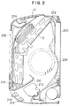
- the indoor unit 10 is covered by a casing 202.
- the casing 202 is detachably secured to the upper and lower edges of a mounting base 200.
- a cross flow fan 204 is disposed at a center portion of the casing 202.
- the cross flow fan 204 is driven by a drive force of a fan motor 70E (that will be described later).
- the cross flow fan 204 sucks air in the room from a sucking opening 206 through various filters 208 and an indoor heat exchanger 16 and supplies the resultant air to the indoor through an air path 210.
- the air path 210 has a horizontal fan 212 and horizontal flaps 214 so as to adjust the direction of the air supplied to the room.
- a drain pan 216 is integrally disposed at the casing 202 corresponding to the lower portion of the indoor heat exchanger 16.
- Fig. 3 shows a refrigerant circuit of the air conditioner controlled by a control unit according to the embodiment of the present invention.
- reference numeral 26 is a compressor.
- Reference numeral 29 is a four-way valve.
- Reference numeral 28 is an outdoor heat exchanger disposed in the outdoor unit 12.
- Reference numeral 30 is a capillary tube.
- Reference numeral 16 is an indoor heat exchanger disposed in the indoor unit 10.
- Reference numeral 24 is an accumulator.
- the refrigerant supplied from the compressor 26 flows in the direction of an arrow denoted by a solid line.
- the refrigerant is compressed in the outdoor heat exchanger 28.
- the refrigerant is evaporated by the indoor heat exchanger 16. Consequently, the room is cooled.
- the refrigerant supplied from the compressor 26 flows in the direction of an arrow denoted by a dotted line.
- the refrigerant is compressed by the indoor heat exchanger 16.
- the refrigerant is evaporated by the outdoor heat exchanger 28. Consequently, the room is heated.
- Reference numeral 112A is a fan motor that constructs an outdoor air supplying device.
- Reference numeral 70E is a fan motor that constructs an indoor air supplying device along with the cross flow fan 204. The fan motor 112A and the fan motor 70E cause air to be supplied to the outdoor heat exchanger 28 and the indoor heat exchanger 16, respectively.
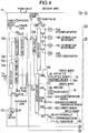
- Fig. 4 shows an electric circuit of the indoor unit 10.
- the electric circuit has a power supply board 70 and a control board 72.
- the power supply board 70 has a drive circuit 70A, a motor power supply circuit 70B, a control circuit power supply circuit 70C, and a serial circuit power supply circuit 70D.
- the drive circuit 70A is connected to the fan motor 70E that controls the air amount supplied to the room.
- the motor power supply circuit 70B generates the power for driving various motors.
- the control circuit power supply circuit 70C generates power for the control circuit.
- the serial circuit power supply circuit 70D generates the power for the serial circuit.
- the fan motor 70E of the embodiment is a DC motor.
- the voltage supplied to the fan motor 70E is controlled with eight bits.
- the air amount can be controlled in 256 levels. This voltage control allows the air amount to be finely controlled for the 1/f fluctuation function.
- the control board 72 has a serial circuit 72A, a drive circuit 72B, and a microcomputer 72C.
- the serial circuit 72A is connected to the serial circuit power supply circuit 70D.
- the drive circuit 72B drives a motor.
- the microcomputer 72C functions as a control circuit.
- the drive circuit 72B is connected to an up/down flap motor 74A, left/right flap motors 74B and 74C, and a floor sensor motor 74D.
- the up/down flap motor 74A vertically moves a flap.
- the floor sensor motor 74D rotates a floor sensor that detects the temperature of the entire surface of the floor.
- the microcomputer 72C is connected to a display LED, an optical sensor 76B, and a receiving circuit 76A.
- the display LED is disposed on the display board 76 and displays an operation mode and so forth.
- the receiving circuit 76a receives an operation signal as infrared rays through the optical sensor 76B from the remote controller 14.
- the microcomputer 72C is connected to an area LED and a floor sensor.
- the area LED is disposed on the sensor plate 78 and displays the temperature detecting area of the floor.
- the remote controller 14 causes the air conditioner to drive the flap motors 74A, 74B, and 74C and change the flap angles and so forth, thereby selecting each mode of heating mode, cooling mode, dry mode, and automatic operating mode, changing the designated temperature, and changing the air supplying amount.
- the microcomputer 72C is connected to a room temperature sensor 80A, a heat exchanger temperature sensor 80B, and a humidity sensor 80C.
- the room temperature sensor 80A detects the room temperature.
- the heat exchanger temperature sensor 80B detects the temperature of the refrigerant coil of the indoor heat exchanger 16.
- the humidity sensor 80C detects the humidity of the room.
- the microcomputer 72C is connected to a self diagnosis LED, an operation selection switch, and a self diagnosis switch that are disposed on the switch board 82. The operation selection switch selects one of the heating mode, the cooling mode, the dry mode, and the automatic operation mode.
- Display LEDs corresponding to the "heating mode” , "cooling mode”, “dry mode”, and “automatic operation mode” are disposed on the display board 76 and light corresponding to the operation modes.
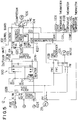
- Fig. 5 shows an electric circuit of the outdoor unit 12. This electric circuit has a rectifier circuit 100 and a control board 102. Terminals (1) to (3) of the electric circuit of the outdoor unit 12 are connected to the electric circuit of the indoor unit 10 shown in Fig. 4.
- the control board 102 has a serial circuit 102A, noise filters 102B, 102C, and 120D, a switching power supply circuit 102E, and a microcomputer 102F.
- the serial circuit 102A is connected to the serial circuit power supply circuit 70D of the indoor unit 10.
- the noise filters 102B, 102C, and 120D remove noise.
- the switching power supply circuit 102E generates a power for switching the inverter 104.
- the microcomputer 102F functions as a control circuit.
- the switching power supply circuit 102E is connected to the inverter 104.
- the inverter 104 is connected to a compressor motor 106 that drives the compressor 26, which compresses the refrigerant.
- the microcomputer 102F is connected to an outer air temperature thermistor 110A, a coil temperature thermistor 110B, and a compressor temperature thermistor 110C.
- the outer air temperature thermistor 110A is an outer temperature sensor that detects the temperature of the outer air.
- the coil temperature thermistor 110B is a coil temperature sensor that detects the temperature of the refrigerant coil of the outdoor heat exchanger 28.
- the compressor temperature thermistor 110C is a temperature sensor that detects the temperature of the compressor 26.
- the noise filter 102B is connected to a fan motor 112A and a fan motor condenser 112B.
- the fan motor 112A supplies air to the outdoor heat exchanger 28.
- the four-way valve 27 and a solenoid valve 29 are connected to the noise filter 102B.
- the fluctuation width (amplitude of air amount) of the 1/f fluctuation function is varied corresponding to the designated reference air amount.
- the microcomputer 72C stores fluctuation width designating maps corresponding to the predetermined reference air amount (see Figs. 6 (A) to (C)).
- One of the fluctuation width designating maps is selected corresponding to the position at which the indoor unit 10 is installed. These maps represent the relation between the reference air amount and fluctuation width corresponding to different installation conditions of the air conditioner.
- the three maps have been stored. However, any one or any two of the maps may be selected and stored. In other words, when the installation condition at which the indoor unit 10 is installed is known, the indoor unit 10 can be operated with only one relation between reference air amount and fluctuation width.
- the fluctuation width increases corresponding to the increase of the air amount. In other words, when the air amount is "weak”, the fluctuation width is also "small”. When the air amount is “strong”, the fluctuation width becomes “large”.
- the fluctuation width is designated so that the ratio of the fluctuation ratio to each air amount is constant.
- the varying ratio of the air amount of the 1/f fluctuation function is constant regardless of the air amount, the user in the room can feel the 1/f fluctuation effect regardless of the air amount.
- the fluctuation width decreases corresponding to the increase of the air amount.
- the fluctuation width is "large”.
- the fluctuation width becomes “weak”. Since the air amount and the fluctuation width are controlled in such a manner, when the air amount is "weak”, the noise of the air amount is low. Thus, so as to satisfactorily employ the 1/f fluctuation function, the fluctuation width is increased.
- the air amount is "strong”, the noise of the air amount is large.
- the fluctuation width is decreased.
- a fluctuation width is designated so that the 1/f fluctuation function can be satisfactorily employed with a predetermined air amount. With other than the predetermined air amount, the fluctuation width is suppressed so as to reduce the noise.
- the air amount when the air amount is "medium”, the 1/f fluctuation function is emphasized. When the air amount is "weak” or “strong”, the noise reduction is emphasized.
- one of (1) 1/f fluctuation emphasizing state (Fig. 6 (A)), (2) low reduction emphasizing state (Fig. 6 (B), and (3) combination state (Fig. 6 (C)) is selected and designated. After the indoor unit is installed, the fluctuation width is controlled corresponding to the selected map. In this embodiment, the 1/f fluctuation emphasizing state is designated.
- the remote controller 14 When the remote controller 14 is operated in the operation stop state and an operation signal is received by the receiving circuit 76A, the code of the received operation signal is analyzed.
- the analyzed result is a power on command or a timer designating command.
- some operation signals of for example temperature designating command and air amount designating command are canceled.
- the receiving circuit 7 is kept in the receiving state.
- the user of the remote controller 14 can designate the timer so that the air conditioner will operates at a predetermined time (for example, two hours later).
- the remote controller 14 outputs a corresponding operation signal to the air conditioner and thereby the timer (on time) is designated in the air conditioner.
- the air conditioner automatically operates two hours later.
- the air conditioner When a power on command is detected, the air conditioner starts in the designated mode of the last operation.
- the code of the received operation signal is analyzed and it is determined whether or not the analyzed result is a power off command, an air amount designating (changing) command, a temperature designating (changing) command, or a timer designating (changing) command.
- the determined result an item corresponding to the analyzed result is selected.
- the operation of the air conditioner is stopped or the designated operation mode is executed.
- the fan motor 70E is controlled.
- the air amount is varied with the fluctuation width corresponding to the designated air amount.
- the air amount that has been designated at present is read. In other words, one of "weak”, “medium”, and “strong” is selected.
- one of the maps shown in Figs. 6 (A) to (C) is read.
- the map that is read is predesignated corresponding to the condition in which the air conditioner is installed.
- the map shown in Fig. 6 (A) is selected.
- the fluctuation width is obtained corresponding to the map. In other words, when the air amount is "weak”, the fluctuation width is "small”. When the air amount is "strong”, the fluctuation width becomes "large”.
- step 306 a command signal that causes the 1/f fluctuation function to be executed corresponding to the map is output. Thereafter, the flow advances to step 308.
- step 308 it is determined whether or not the reference air amount has been changed.
- the flow returns to step 300 so as to repeat the above-described process.
- the flow advances to step 310.
- step 310 it is determined whether or not the 1/f fluctuation function has been canceled.
- step 312. a signal for causing the 1/f fluctuation function to be canceled is output. Thus, this routine is finished.
- the map shown in Fig. 6 (A) is selected.
- the map shown in Fig. 6 (B) is selected, when the air amount is "weak", the fluctuation width becomes “large”. When the air amount is "strong”, the fluctuation width becomes "low”.
- the noise can be equalized regardless of the reference air amount.
- the noise can be more reduced than the case of which the fluctuation width is constant.
- the fluctuation width is varied corresponding to the reference air amount
- effects that have not accomplished for example, the emphasis of the 1/f fluctuation function, the emphasis of the noise, or the antinomy of the improvement of 1/f fluctuation function and the noise reduction
- the noise reduction can be emphasized (with the map shown in Fig. 6 (B)).
- the 1/f fluctuation function can be improved so as to save energy (with the map shown in Fig. 6 (A)).
- the three types of fluctuation width designating maps have been stored in the microcomputer 72C.
- the air conditioner When the air conditioner is installed, one of the maps is selected. However, it should be noted that more than three types of maps may be prepared.
- the user after the air conditioner is installed, the user can select one of the maps. Instead, one of the maps may be stored.
- a fluctuation width to each reference air amount is designated so that the ratio of the fluctuation width thereto becomes constant.
- the user can feel the comfortableness of the 1/f fluctuation regardless of any reference air amount.
- the noise of the air supplying means can be kept constant regardless of the predetermined reference air amount. Thus, the discomfortableness of the noise can be removed.
- the fundamental functions (coolness, warmness, and so forth) of the air conditioner are improved.
- the noise of the air conditioner is reduced.
- the comfortableness of the user can be totally improved.
Landscapes
- Engineering & Computer Science (AREA)
- Chemical & Material Sciences (AREA)
- Combustion & Propulsion (AREA)
- Mechanical Engineering (AREA)
- General Engineering & Computer Science (AREA)
- Physics & Mathematics (AREA)
- Human Computer Interaction (AREA)
- Signal Processing (AREA)
- Automation & Control Theory (AREA)
- General Physics & Mathematics (AREA)
- Fluid Mechanics (AREA)
- Thermal Sciences (AREA)
- Fuzzy Systems (AREA)
- Mathematical Physics (AREA)
- Air Conditioning Control Device (AREA)
- Control Of Positive-Displacement Air Blowers (AREA)
Applications Claiming Priority (2)
| Application Number | Priority Date | Filing Date | Title |
|---|---|---|---|
| JP220544/94 | 1994-09-14 | ||
| JP6220544A JPH0886502A (ja) | 1994-09-14 | 1994-09-14 | 空気調和機 |
Publications (2)
| Publication Number | Publication Date |
|---|---|
| EP0702198A2 true EP0702198A2 (fr) | 1996-03-20 |
| EP0702198A3 EP0702198A3 (fr) | 1996-10-09 |
Family
ID=16752659
Family Applications (1)
| Application Number | Title | Priority Date | Filing Date |
|---|---|---|---|
| EP95305983A Withdrawn EP0702198A3 (fr) | 1994-09-14 | 1995-08-24 | Appareil de climatisation |
Country Status (8)
| Country | Link |
|---|---|
| US (1) | US5657640A (fr) |
| EP (1) | EP0702198A3 (fr) |
| JP (1) | JPH0886502A (fr) |
| KR (1) | KR100315155B1 (fr) |
| CN (1) | CN1135338C (fr) |
| BR (1) | BR9504012A (fr) |
| CA (1) | CA2156879C (fr) |
| TW (1) | TW341643B (fr) |
Cited By (3)
| Publication number | Priority date | Publication date | Assignee | Title |
|---|---|---|---|---|
| WO2006024066A1 (fr) * | 2004-09-02 | 2006-03-09 | The State Of Queensland (Acting Through Its Department Of Public Works) | Systeme de climatisation |
| CN106556122A (zh) * | 2016-12-30 | 2017-04-05 | 广东美的制冷设备有限公司 | 控制系统、睡眠控制装置、空调器及其睡眠控制方法 |
| CN117128626A (zh) * | 2023-07-21 | 2023-11-28 | 江森自控日立万宝空调(广州)有限公司 | 自然冷却空调机组冷却模式的自适应调节方法 |
Families Citing this family (11)
| Publication number | Priority date | Publication date | Assignee | Title |
|---|---|---|---|---|
| JP3433072B2 (ja) * | 1997-10-29 | 2003-08-04 | 三洋電機株式会社 | 空気調和機 |
| KR20000063261A (ko) * | 2000-06-09 | 2000-11-06 | 최운용 | 폐도자기와 폐애자를 경량 골재 대체재와 포장용 골재로사용하는 재활용법 |
| KR20020066459A (ko) * | 2001-02-10 | 2002-08-17 | 허창린 | 폐자재를 이용한 투수 블록 및 그 제조방법 |
| JP2003194385A (ja) * | 2001-12-28 | 2003-07-09 | Daikin Ind Ltd | 空気調和機 |
| US7145108B2 (en) * | 2003-07-22 | 2006-12-05 | Kaz, Incorporated | Configurable heating pad controller |
| JP6077245B2 (ja) * | 2012-09-13 | 2017-02-08 | ダイキン工業株式会社 | 空調室内機 |
| CN104566792B (zh) * | 2014-12-17 | 2018-03-09 | 美的集团股份有限公司 | 空调器、空调器的控制方法及系统 |
| JP2018091154A (ja) * | 2016-11-30 | 2018-06-14 | パナソニックIpマネジメント株式会社 | 送風装置および送風制御プログラム |
| WO2018100951A1 (fr) * | 2016-11-30 | 2018-06-07 | パナソニックIpマネジメント株式会社 | Dispositif de soufflage et programme de commande de soufflage |
| CN109114739B (zh) * | 2018-06-05 | 2020-09-25 | 青岛海尔空调器有限总公司 | 一种空调室内机控制方法及系统 |
| JP7715675B2 (ja) * | 2022-04-28 | 2025-07-30 | 株式会社コロナ | 温風暖房機 |
Family Cites Families (7)
| Publication number | Priority date | Publication date | Assignee | Title |
|---|---|---|---|---|
| JPS5623657A (en) * | 1979-07-31 | 1981-03-06 | Nissan Motor Co Ltd | Fan motor control system for air conditioner |
| JPS5938114A (ja) * | 1982-08-24 | 1984-03-01 | Mitsubishi Electric Corp | 自動車用冷房装置 |
| JP2513048B2 (ja) * | 1989-11-20 | 1996-07-03 | 株式会社富士通ゼネラル | 空気調和機の制御方法 |
| JP2801699B2 (ja) * | 1989-11-20 | 1998-09-21 | 株式会社東芝 | 空気調和機 |
| JPH03160263A (ja) * | 1989-11-20 | 1991-07-10 | Fujitsu General Ltd | 空気調和機の制御方法 |
| JPH05223330A (ja) * | 1992-02-07 | 1993-08-31 | Sharp Corp | 空気調和機 |
| JPH06229612A (ja) * | 1993-02-03 | 1994-08-19 | Sharp Corp | 空気調和機 |
-
1994
- 1994-09-14 JP JP6220544A patent/JPH0886502A/ja active Pending
-
1995
- 1995-02-16 TW TW084101390A patent/TW341643B/zh active
- 1995-03-15 KR KR1019950005349A patent/KR100315155B1/ko not_active Expired - Fee Related
- 1995-08-24 EP EP95305983A patent/EP0702198A3/fr not_active Withdrawn
- 1995-08-24 CA CA002156879A patent/CA2156879C/fr not_active Expired - Fee Related
- 1995-09-13 BR BR9504012A patent/BR9504012A/pt not_active IP Right Cessation
- 1995-09-13 CN CNB951168800A patent/CN1135338C/zh not_active Expired - Fee Related
- 1995-09-14 US US08/528,146 patent/US5657640A/en not_active Expired - Lifetime
Non-Patent Citations (1)
| Title |
|---|
| None |
Cited By (4)
| Publication number | Priority date | Publication date | Assignee | Title |
|---|---|---|---|---|
| WO2006024066A1 (fr) * | 2004-09-02 | 2006-03-09 | The State Of Queensland (Acting Through Its Department Of Public Works) | Systeme de climatisation |
| CN106556122A (zh) * | 2016-12-30 | 2017-04-05 | 广东美的制冷设备有限公司 | 控制系统、睡眠控制装置、空调器及其睡眠控制方法 |
| CN106556122B (zh) * | 2016-12-30 | 2019-11-08 | 广东美的制冷设备有限公司 | 控制系统、睡眠控制装置、空调器及其睡眠控制方法 |
| CN117128626A (zh) * | 2023-07-21 | 2023-11-28 | 江森自控日立万宝空调(广州)有限公司 | 自然冷却空调机组冷却模式的自适应调节方法 |
Also Published As
| Publication number | Publication date |
|---|---|
| TW341643B (en) | 1998-10-01 |
| CA2156879C (fr) | 2000-10-17 |
| BR9504012A (pt) | 1996-09-24 |
| CA2156879A1 (fr) | 1996-03-15 |
| CN1135338C (zh) | 2004-01-21 |
| KR100315155B1 (ko) | 2002-07-02 |
| EP0702198A3 (fr) | 1996-10-09 |
| CN1129306A (zh) | 1996-08-21 |
| JPH0886502A (ja) | 1996-04-02 |
| KR960011332A (ko) | 1996-04-20 |
| US5657640A (en) | 1997-08-19 |
Similar Documents
| Publication | Publication Date | Title |
|---|---|---|
| CA2156879C (fr) | Appareil de climatisation | |
| US5467606A (en) | Air conditioning apparatus capable of operating in cooling mode and heating mode | |
| JP3163121B2 (ja) | 空気調和機 | |
| EP0774631B1 (fr) | Dispositif de climatisation comportant des moyens de régulation de la pression de frigorigène et procédé de commande d'entraínement pour celui-ci | |
| US4939910A (en) | Air conditioner | |
| US4997030A (en) | Central air conditioning system having remote controller in a plurality of rooms for starting or stopping air conditioning apparatus | |
| CA2149802C (fr) | Conditionneur d'air | |
| US4656571A (en) | Frequency converting device and control method therefor | |
| CA2158489C (fr) | Conditionneur d'air | |
| JP3475014B2 (ja) | 空気調和機 | |
| US4697430A (en) | Air conditioner with a radiant temperature control | |
| EP0427486B1 (fr) | Appareil de conditionnement | |
| JPH0989347A (ja) | 空気調和機 | |
| JP4259668B2 (ja) | 空気調和機 | |
| JPH0854138A (ja) | 空気調和機 | |
| JP3306126B2 (ja) | 空気調和機 | |
| JP3181111B2 (ja) | 空気調和機 | |
| JPS5927145A (ja) | 空気調和機 | |
| JPH10197030A (ja) | 空気調和機 | |
| JPH0861738A (ja) | 空気調和機 | |
| JP3423209B2 (ja) | 暖房システム | |
| KR940005318Y1 (ko) | 냉,난방 겸용 에어컨의 난방 제어장치 | |
| JPH03241259A (ja) | 空気調和機の風量制御方法 | |
| JP3133616B2 (ja) | 空気調和機の制御装置 | |
| JPH03164645A (ja) | 空気調和装置 |
Legal Events
| Date | Code | Title | Description |
|---|---|---|---|
| PUAI | Public reference made under article 153(3) epc to a published international application that has entered the european phase |
Free format text: ORIGINAL CODE: 0009012 |
|
| AK | Designated contracting states |
Kind code of ref document: A2 Designated state(s): DE FR GB IT |
|
| PUAL | Search report despatched |
Free format text: ORIGINAL CODE: 0009013 |
|
| AK | Designated contracting states |
Kind code of ref document: A3 Designated state(s): DE FR GB IT |
|
| 17P | Request for examination filed |
Effective date: 19961209 |
|
| 17Q | First examination report despatched |
Effective date: 19980701 |
|
| STAA | Information on the status of an ep patent application or granted ep patent |
Free format text: STATUS: THE APPLICATION IS DEEMED TO BE WITHDRAWN |
|
| 18D | Application deemed to be withdrawn |
Effective date: 19981112 |