EP0702254B1 - Spleisserverbinderelement für Glasfasern - Google Patents
Spleisserverbinderelement für Glasfasern Download PDFInfo
- Publication number
- EP0702254B1 EP0702254B1 EP95118521A EP95118521A EP0702254B1 EP 0702254 B1 EP0702254 B1 EP 0702254B1 EP 95118521 A EP95118521 A EP 95118521A EP 95118521 A EP95118521 A EP 95118521A EP 0702254 B1 EP0702254 B1 EP 0702254B1
- Authority
- EP
- European Patent Office
- Prior art keywords
- splicer
- fiber
- tool
- aperture
- splice element
- Prior art date
- Legal status (The legal status is an assumption and is not a legal conclusion. Google has not performed a legal analysis and makes no representation as to the accuracy of the status listed.)
- Expired - Lifetime
Links
- 239000000835 fiber Substances 0.000 title claims description 163
- 239000013307 optical fiber Substances 0.000 claims description 18
- 238000005253 cladding Methods 0.000 description 44
- 229910003460 diamond Inorganic materials 0.000 description 16
- 239000010432 diamond Substances 0.000 description 16
- 229920000642 polymer Polymers 0.000 description 15
- 230000006870 function Effects 0.000 description 10
- 229910052751 metal Inorganic materials 0.000 description 10
- 239000002184 metal Substances 0.000 description 10
- 238000003780 insertion Methods 0.000 description 8
- 230000037431 insertion Effects 0.000 description 8
- 230000000295 complement effect Effects 0.000 description 7
- 238000010438 heat treatment Methods 0.000 description 5
- 230000007704 transition Effects 0.000 description 5
- 229910000838 Al alloy Inorganic materials 0.000 description 4
- 238000007743 anodising Methods 0.000 description 4
- 238000003825 pressing Methods 0.000 description 4
- SYJPAKDNFZLSMV-HYXAFXHYSA-N (Z)-2-methylpropanal oxime Chemical compound CC(C)\C=N/O SYJPAKDNFZLSMV-HYXAFXHYSA-N 0.000 description 3
- 229910045601 alloy Inorganic materials 0.000 description 3
- 239000000956 alloy Substances 0.000 description 3
- 239000011521 glass Substances 0.000 description 3
- 238000010276 construction Methods 0.000 description 2
- 230000005489 elastic deformation Effects 0.000 description 2
- 239000000463 material Substances 0.000 description 2
- 239000000155 melt Substances 0.000 description 2
- 238000007792 addition Methods 0.000 description 1
- PNEYBMLMFCGWSK-UHFFFAOYSA-N aluminium oxide Inorganic materials [O-2].[O-2].[O-2].[Al+3].[Al+3] PNEYBMLMFCGWSK-UHFFFAOYSA-N 0.000 description 1
- KGBXLFKZBHKPEV-UHFFFAOYSA-N boric acid Chemical compound OB(O)O KGBXLFKZBHKPEV-UHFFFAOYSA-N 0.000 description 1
- 239000004327 boric acid Substances 0.000 description 1
- 230000008859 change Effects 0.000 description 1
- 238000012217 deletion Methods 0.000 description 1
- 230000037430 deletion Effects 0.000 description 1
- 238000006073 displacement reaction Methods 0.000 description 1
- 239000003792 electrolyte Substances 0.000 description 1
- 239000003365 glass fiber Substances 0.000 description 1
- 238000004519 manufacturing process Methods 0.000 description 1
- 239000007769 metal material Substances 0.000 description 1
- 150000002739 metals Chemical class 0.000 description 1
- 238000000034 method Methods 0.000 description 1
- 238000012986 modification Methods 0.000 description 1
- 230000004048 modification Effects 0.000 description 1
- 238000000465 moulding Methods 0.000 description 1
- 230000003287 optical effect Effects 0.000 description 1
- LJCNRYVRMXRIQR-OLXYHTOASA-L potassium sodium L-tartrate Chemical compound [Na+].[K+].[O-]C(=O)[C@H](O)[C@@H](O)C([O-])=O LJCNRYVRMXRIQR-OLXYHTOASA-L 0.000 description 1
- 230000008439 repair process Effects 0.000 description 1
- 239000001476 sodium potassium tartrate Substances 0.000 description 1
- 235000011006 sodium potassium tartrate Nutrition 0.000 description 1
- 235000013599 spices Nutrition 0.000 description 1
- 230000003068 static effect Effects 0.000 description 1
- 230000000007 visual effect Effects 0.000 description 1
Images



Classifications
-
- G—PHYSICS
- G02—OPTICS
- G02B—OPTICAL ELEMENTS, SYSTEMS OR APPARATUS
- G02B6/00—Light guides; Structural details of arrangements comprising light guides and other optical elements, e.g. couplings
- G02B6/24—Coupling light guides
- G02B6/36—Mechanical coupling means
- G02B6/38—Mechanical coupling means having fibre to fibre mating means
- G02B6/3801—Permanent connections, i.e. wherein fibres are kept aligned by mechanical means
- G02B6/3802—Assembly tools, e.g. crimping tool or pressing bench
-
- G—PHYSICS
- G02—OPTICS
- G02B—OPTICAL ELEMENTS, SYSTEMS OR APPARATUS
- G02B6/00—Light guides; Structural details of arrangements comprising light guides and other optical elements, e.g. couplings
- G02B6/24—Coupling light guides
- G02B6/36—Mechanical coupling means
- G02B6/38—Mechanical coupling means having fibre to fibre mating means
- G02B6/3801—Permanent connections, i.e. wherein fibres are kept aligned by mechanical means
-
- G—PHYSICS
- G02—OPTICS
- G02B—OPTICAL ELEMENTS, SYSTEMS OR APPARATUS
- G02B6/00—Light guides; Structural details of arrangements comprising light guides and other optical elements, e.g. couplings
- G02B6/24—Coupling light guides
- G02B6/36—Mechanical coupling means
- G02B6/38—Mechanical coupling means having fibre to fibre mating means
- G02B6/3801—Permanent connections, i.e. wherein fibres are kept aligned by mechanical means
- G02B6/3806—Semi-permanent connections, i.e. wherein the mechanical means keeping the fibres aligned allow for removal of the fibres
-
- G—PHYSICS
- G02—OPTICS
- G02B—OPTICAL ELEMENTS, SYSTEMS OR APPARATUS
- G02B6/00—Light guides; Structural details of arrangements comprising light guides and other optical elements, e.g. couplings
- G02B6/24—Coupling light guides
- G02B6/36—Mechanical coupling means
- G02B6/38—Mechanical coupling means having fibre to fibre mating means
- G02B6/3807—Dismountable connectors, i.e. comprising plugs
- G02B6/3898—Tools, e.g. handheld; Tuning wrenches; Jigs used with connectors, e.g. for extracting, removing or inserting in a panel, for engaging or coupling connectors, for assembling or disassembling components within the connector, for applying clips to hold two connectors together or for crimping
Definitions
- each of the two fibers to be spliced can be inserted in each end of the splicer independently of each other and without disturbing a fiber that has already been inserted in the one of the ends. This allows one craftsperson to insert the fibers and also allows one craftsperson to reenter the splicer for the purpose of removing one of the fibers for repair or replacement without disturbing the other fiber.
- the independent insertion of the fibers allows the splicer utilising the splice element of the present invention to be mounted in panels in relatively high densities. All of the fibers on one side of the panel can be inserted in the associated one of the splicers without disturbing any fibers that may have been inserted on the other side. Those other side fibers, if not already inserted in the splicer panel, can be inserted by the same craftsperson who inserted the fibers in the one side splicers without disturbing those inserted fibers. Alternatively, the insertion of those other side fibers can be left for a later time or even another craftsperson.
- the length of tool 20 is such that the tool only projects inwardly into housing 14 a distance sufficient to open only spring clamps 26 and 28 and not to affect any fiber that may have been received in the associated one of the apertures in end 24 and is held in place in splicer 10 by clamps 28 and 30.
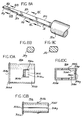
- Element half 82b includes upwardly projecting alignment boss or pin 96b and complementary alignment hole or opening 98b.
- alignment boss or pin 96b on element half 82b interferes with complementary alignment hole or opening 98a on element half 82a.
- Opening 98b on element half 82b interferes with the pin 96a on element half 82a.
- Fig. 4e shows the splice 82 and groove 109 after a fiber has been inserted in aperture 18 and the cladding 20a has entered groove 109 and the tool has rotated in the opposite direction to thereby remove the force it is providing to deflect the spring clamps.
- This will be referred to hereinafter as the operating mode of splicer 10.
- the space between the edges of splice element halves 82a and 82b is designated as "c”.
- the width "a" of groove 109 is selected to provide the desired spacing "c" in the operating mode.
- the metallic material out of which element 82 is fabricated not be subject to plastic deformation when the fiber is pulled by the above force. If the material is such as to undergo plastic deformation then the shape of V groove 109 would change and it would be necessary to also replace splicer 10 as well as prepare the fiber for reinsertion into the splicer. Elastic deformation is, on the other hand, desirable for alignment of different fiber diameters. We have found after evaluating various aluminum alloys for use in fabricating the splice element that the higher strength alloys are better for that purpose (elastic deformation without plastic deformation) than the lower strength alloys.
- splicer 10 will now be described with respect to end 16 and fiber 20, it being understood, however, that this description also applies to fiber 21 inserted into or removed from end 24.
- a craftsperson will first prepare the fiber in the manner described above. The craftsperson would then, using one hand, insert tool 12 into aperture 22. The orientation of the tool with respect to aperture 22 just prior to insertion is shown in Fig. 1. The craftsperson would then rotate the tool in the direction which maximally deflects spring clamps 26 and 28.
- body halves 14a, 14b from a glass filled, high performance polymer will satisfy the above criteria.
- those halves were fabricated using such a polymer which is commercially available from General Electric and is sold under the trademark VALOX.
- FIG. 6a shows that splicer 110 fully assembled while Fig. 6b shows one of the two splice body halves 114a, 114b.
- section 134b has first and second tapered half rectangularly shaped portions 160b and 164b and first and second half rectangularly shaped portions 162b and 166b.
- half rectangularly shaped portions 162b and 166b in combination with half rectangularly shaped portions 162a and 166a of body half 114a define elongated rectangles 162 and 166, respectively whose heights are sufficient to hold in place a 900 um and a 500 um buffer, respectively.
- section 132b has a tapered half rectangularly shaped portion 168b and a half rectangularly shaped portion 170b.
- Section 130b shown in Fig. 6b need not be described in detail as it is identical in structure and function to section 28b of body half 14b of splicer 10.
- the rest of body half 114b need be described as it is identical in structure and function to those parts of body half 14b which are designated by reference numerals which only differ from those shown in Fig. 6b by the absence of a hundreds position.
- tool 12 has been shown to have a handle 12a which is substantially coaxial with the axis of shaft 12b, it should be appreciated that the handle may also be offset with respect to the shaft axis.
- edges 112h, 112j, and 112k of portions 112b, 112c and 112d, respectively, are rounded.
- ferrule 306 includes at end 306c the raised edge 306d.
- edge 306d abuts the front 300b of panel 300. Therefore, when ferrule 306 is fully inserted in panel 300, tabs 308 and raised edge 306d cooperate to firmly hold the combination of ferrule and splicer in panel 300.
Landscapes
- Physics & Mathematics (AREA)
- General Physics & Mathematics (AREA)
- Optics & Photonics (AREA)
- Mechanical Coupling Of Light Guides (AREA)
Claims (3)
- Spleißelement (82) für eine Verwendung in einem Spleißer für das Spleißen von mindestens zwei Lichtleitfasern (20, 21), wobei das Element (82) ein erstes und ein zweites zusammenwirkendes Teil (82a, 82b) aufweist und dadurch gekennzeichnet ist, daß die Teile im wesentlichen Spiegelbilder voneinander sind, wobei jedes der Teile (82a, 82b) einen Körper aufweist, der eine im allgemeinen ebene Fläche mit einer sich darin in Längsrichtung erstreckenden V-förmigen Faseraufnahmenut (109a; 109b) aufweist, und wobei die Fläche ebenfalls darin eine Werkzeugaufnahmenut (103) aufweist, wobei sich die Werkzeugaufnahmenut in Längsrichtung der Fläche erstreckt und von der sich in Längsrichtung erstreckenden Faseraufnahmenut (109a; 109b) beabstandet ist, wodurch, wenn die Teile miteinander in Eingriff sind, das Spleißelement aufweist: einen sich in Längsrichtung erstreckenden Durchgang, der durch die Faseraufnahmenuten für das Aufnehmen der Enden von zwei Lichtleitfasern definiert wird, die aus entgegengesetzten Richtungen in den Durchgang eingesetzt werden; und einen sich in Längsrichtung erstreckenden Werkzeugaufnahmedurchgang, der durch die Werkzeugaufnahmenuten (103) für das Aufnehmen eines Werkzeuges in Längsrichtung definiert wird, das bei der Verwendung manipulierbar ist, um die Teile (82a, 82b) relativ zueinander zu verschieben, um die Bewegung der Lichtleitfasern im Lichtleitfaseraufnahmedurchgang zu erleichtern.
- Spleißelement nach Anspruch 1, bei dem die Teile (82a, 82b) eine Verriegelungseinrichtung (96, 98) für das Sichern der Teile (82a, 82b) aneinander enthalten.
- Spleißelement nach Anspruch 2, dadurch gekennzeichnet, daß die Verriegelungseinrichtung (96, 98) an jedem der Teile (82a, 82b) einen aufrechtstehenden Bolzen (98a, 96b) aufweist, der als eine Preßpassung in einer entsprechenden Öffnung (98b, 96a) in dem anderen der Teile in Eingriff kommen kann.
Applications Claiming Priority (3)
| Application Number | Priority Date | Filing Date | Title |
|---|---|---|---|
| US07/579,127 US5121456A (en) | 1990-09-06 | 1990-09-06 | Polymer spring fiber optic splicer, tool for operating same and panel incorporating same |
| US579127 | 1990-09-06 | ||
| EP91306136A EP0479415B1 (de) | 1990-09-06 | 1991-07-05 | Spleissverbinder für Glasfasern |
Related Parent Applications (2)
| Application Number | Title | Priority Date | Filing Date |
|---|---|---|---|
| EP91306136A Division EP0479415B1 (de) | 1990-09-06 | 1991-07-05 | Spleissverbinder für Glasfasern |
| EP91306136.2 Division | 1991-07-05 |
Publications (3)
| Publication Number | Publication Date |
|---|---|
| EP0702254A2 EP0702254A2 (de) | 1996-03-20 |
| EP0702254A3 EP0702254A3 (de) | 1996-10-02 |
| EP0702254B1 true EP0702254B1 (de) | 2002-10-02 |
Family
ID=24315676
Family Applications (2)
| Application Number | Title | Priority Date | Filing Date |
|---|---|---|---|
| EP95118521A Expired - Lifetime EP0702254B1 (de) | 1990-09-06 | 1991-07-05 | Spleisserverbinderelement für Glasfasern |
| EP91306136A Expired - Lifetime EP0479415B1 (de) | 1990-09-06 | 1991-07-05 | Spleissverbinder für Glasfasern |
Family Applications After (1)
| Application Number | Title | Priority Date | Filing Date |
|---|---|---|---|
| EP91306136A Expired - Lifetime EP0479415B1 (de) | 1990-09-06 | 1991-07-05 | Spleissverbinder für Glasfasern |
Country Status (5)
| Country | Link |
|---|---|
| US (1) | US5121456A (de) |
| EP (2) | EP0702254B1 (de) |
| JP (1) | JP3061306B2 (de) |
| CA (1) | CA2046564C (de) |
| DE (2) | DE69133124T2 (de) |
Families Citing this family (52)
| Publication number | Priority date | Publication date | Assignee | Title |
|---|---|---|---|---|
| USD334734S (en) | 1990-09-06 | 1993-04-13 | Reliance Comm/Tec Corporation | Optical fiber splicer |
| US5204929A (en) * | 1991-09-04 | 1993-04-20 | Reliance Comm/Tec Corporation | Fiber patch panel |
| US5309538A (en) * | 1991-09-06 | 1994-05-03 | Minnesota Mining And Manufacturing Company | Reinforced multiple optical fiber splice having preanodized element |
| US5155787A (en) * | 1991-09-06 | 1992-10-13 | Minnesota Mining And Manufacturing Company | Multiple optical fiber splice element having ramped porch |
| US5191632A (en) * | 1991-09-20 | 1993-03-02 | Minnesota Mining And Manufacturing Company | Splice actuator tool |
| US5263105A (en) * | 1992-05-29 | 1993-11-16 | E. I. Du Pont De Nemours And Company | Connector assembly for connecting an optical fiber cable to a socket |
| US5367594A (en) * | 1992-09-01 | 1994-11-22 | The Whitaker Corporation | Fiber optic splicer-connector |
| US5392373A (en) * | 1993-11-29 | 1995-02-21 | The Whitaker Corporation | Apparatus for optically coupling an optical fiber to an electro-optic device |
| US5440657A (en) * | 1994-05-26 | 1995-08-08 | The Whitaker Corporation | Re-enterable splicer for ribbon fiber |
| US5450517A (en) * | 1994-07-01 | 1995-09-12 | The Whitaker Corporation | Re-enterable fiber optic splicer for data communications |
| US5613030A (en) * | 1995-05-15 | 1997-03-18 | The Whitaker Corporation | High density fiber optic interconnection enclosure |
| US5682450A (en) * | 1995-06-29 | 1997-10-28 | Minnesota Mining And Manufacturing Company | Fiber optic connector element |
| US5734770A (en) * | 1995-06-29 | 1998-03-31 | Minnesota Mining And Manufacturing Company | Cleave and bevel fiber optic connector |
| TW333616B (en) * | 1995-06-29 | 1998-06-11 | Minnesota Mining & Mfg | Bare fiber connector |
| US5717812A (en) * | 1995-09-06 | 1998-02-10 | The Whitaker Corporation | Holder for fiber optic splice connectors |
| USD385849S (en) * | 1995-09-26 | 1997-11-04 | Minnesota Mining And Manufacturing Company | Compact single mode bare fiber connector |
| US5724467A (en) * | 1995-10-11 | 1998-03-03 | The Whitaker Corporation | Adapter to secure fiber optic connectors within a telecommuniations box |
| US5638477A (en) * | 1995-12-22 | 1997-06-10 | Minnesota Mining And Manufacturing Company | Strain relief means for optical fiber splicing member and improved tool for making the splice |
| GB2312968B (en) * | 1996-05-09 | 2000-09-13 | Daewoo Telecom Ltd | Splicer for light waveguides |
| JPH11218644A (ja) * | 1997-11-13 | 1999-08-10 | Whitaker Corp:The | 光ファイバ装置及び光ファイバ副組立体 |
| US6247850B1 (en) | 1998-11-02 | 2001-06-19 | The Whitaker Corporation | Multiple fiber splice element and connector |
| US6200040B1 (en) | 1997-11-13 | 2001-03-13 | Tyco Electronics | Fiber splaying pin keeper for fiber optic connector |
| US6210047B1 (en) * | 2000-02-04 | 2001-04-03 | Molex Incorporated | Method of fabricating a fiber optic connector ferrule |
| AU6255101A (en) | 2000-06-12 | 2001-12-24 | Krone Gmbh | Assembly and method for use in terminating an optical fibre or fibres |
| JP3977335B2 (ja) * | 2002-02-08 | 2007-09-19 | 株式会社フジクラ | 光ファイバ接続方法及び光ファイバ接続工具 |
| GB2385147A (en) | 2002-02-08 | 2003-08-13 | Simon Charles Gilligan | Fibre-optic connector having plunger to move adhesive |
| US6918703B2 (en) * | 2002-06-12 | 2005-07-19 | Molex Incorporated | System for terminating optical fibers in a fiber optic connector |
| US20030230688A1 (en) * | 2002-06-17 | 2003-12-18 | Kiyohiko Hase | Merchandise display hooks and merchandise suspension arms used therein |
| US6816662B2 (en) | 2002-09-19 | 2004-11-09 | 3M Innovative Properties Company | Article for cleaving and polishing optical fiber ends |
| US6870996B2 (en) | 2002-09-19 | 2005-03-22 | 3M Innovative Properties Company | Optical fiber plug including fiber positioning holder |
| US6848838B2 (en) | 2002-09-19 | 2005-02-01 | 3M Innovative Properties Company | Optical fiber plug |
| CA2446533A1 (en) * | 2003-10-24 | 2005-04-24 | 9134-9001 Quebec Inc. | Flexible ferrule device for connection of optical fiber and use thereof |
| US7001084B2 (en) * | 2003-12-30 | 2006-02-21 | 3M Innovative Properties Company | Fiber splice device |
| GB0412003D0 (en) * | 2004-05-28 | 2004-06-30 | Tyco Electronics Raychem Nv | Optical fibre connector |
| US7331719B2 (en) * | 2004-06-30 | 2008-02-19 | Tyco Electronics Corporation | Optical fiber clamping assembly |
| US20060002662A1 (en) * | 2004-06-30 | 2006-01-05 | Tyco Electronics Corporation | Small form factor, field-installable connector |
| JP2006350209A (ja) * | 2005-06-20 | 2006-12-28 | Yoshinari Kono | メカニカルスプライス |
| US7534050B2 (en) | 2007-04-13 | 2009-05-19 | Adc Telecommunications, Inc. | Field terminatable fiber optic connector assembly |
| WO2009045562A1 (en) | 2007-04-13 | 2009-04-09 | Adc Telecommunications, Inc. | Optical fiber field termination kit |
| US7530746B2 (en) | 2007-04-13 | 2009-05-12 | Abc Telecommunications, Inc. | Field termination connector with shaped adhesive pre-form |
| KR20100075928A (ko) * | 2007-09-18 | 2010-07-05 | 파스옵트스 인크. | 소산장 광섬유 장치 |
| US8083416B2 (en) | 2007-11-30 | 2011-12-27 | Adc Telecommunications, Inc. | Hybrid fiber/copper connector system and method |
| JP4609954B2 (ja) * | 2009-04-28 | 2011-01-12 | 古河電気工業株式会社 | 光ファイバ用接続構造及び現場付け光コネクタ |
| US8636425B2 (en) | 2011-03-15 | 2014-01-28 | Adc Telecommunications, Inc. | Fiber optic connector |
| US8494331B2 (en) | 2011-07-06 | 2013-07-23 | Go!Foton Holdings, Inc. | Apparatus and method for mass producing optical fiber splice-on connector subunits |
| US8506178B2 (en) | 2011-06-24 | 2013-08-13 | Go!Foton Holdings, Inc. | Mechanical splicer apparatus for fiber optic cables |
| US8506179B2 (en) * | 2011-07-21 | 2013-08-13 | Go!Foton Holdings, Inc. | Deformable plastic radially symmetric mechanical splicers and connectors for optical fibers |
| CN104364686B (zh) | 2012-02-07 | 2016-11-16 | 泰科电子瑞侃有限公司 | 用于连接器的线缆端接组件和方法 |
| US9176285B2 (en) | 2012-05-03 | 2015-11-03 | Adc Telecommunications, Inc. | Fiber optic connector |
| CN103852826B (zh) * | 2012-12-05 | 2015-07-22 | 天津中之杰能源技术有限公司 | 光纤接头辅助安装器 |
| CN105773482B (zh) * | 2016-05-04 | 2017-07-04 | 湖州优创科技有限公司 | 一种网络光纤线的检测夹具 |
| WO2017216753A1 (en) | 2016-06-16 | 2017-12-21 | O’Fiberty Sa | Fiber cleaver |
Citations (1)
| Publication number | Priority date | Publication date | Assignee | Title |
|---|---|---|---|---|
| US4029390A (en) * | 1974-12-23 | 1977-06-14 | Bell Telephone Laboratories, Incorporated | Optical fiber group splicing technique and apparatus employing unique foldable holder |
Family Cites Families (22)
| Publication number | Priority date | Publication date | Assignee | Title |
|---|---|---|---|---|
| JPS5387246A (en) * | 1977-01-11 | 1978-08-01 | Dainichi Nippon Cables Ltd | Connection part of light fiber |
| GB1600272A (en) * | 1977-05-02 | 1981-10-14 | Plessey Co Ltd | Optical fibre connectors |
| BR7802609A (pt) * | 1977-05-10 | 1978-12-26 | Cselt Centro Studi Lab Telecom | Dispositivo de uniao de fibras oticas ou condutores |
| JPS56102816A (en) * | 1980-01-21 | 1981-08-17 | Nippon Telegr & Teleph Corp <Ntt> | Connector for optical fiber core |
| US4391487A (en) * | 1981-01-07 | 1983-07-05 | Gte Laboratories Incorporated | Optical fiber centering device |
| CA1158900A (en) * | 1981-01-14 | 1983-12-20 | Lucas Soes | Connector for use in butt splicing two optical fibres |
| FR2513392B1 (fr) * | 1981-09-23 | 1986-06-27 | Clement Jean Joseph | Cellule de centrage pour raccordement de fibres optiques |
| FR2538919B1 (fr) * | 1983-01-05 | 1987-01-09 | Telecommunications Sa | Dispositif de raccordement rapide des extremites de fibres optiques |
| DE3482500D1 (de) * | 1983-03-11 | 1990-07-19 | Alliance Tech Ind | Verfahren und vorrichtung zum verbinden optischer fasern. |
| JPS61252509A (ja) * | 1985-05-02 | 1986-11-10 | Seiko Giken:Kk | 光コネクタスリ−ブおよび光コネクタスリ−ブ加工用治具 |
| NL8503409A (nl) * | 1985-12-11 | 1987-07-01 | Philips Nv | Inrichting voor het verbinden van lichtgeleidende vezels. |
| US4729619A (en) * | 1986-05-01 | 1988-03-08 | Minnesota Mining And Manufacturing Company | Optical fiber connector incorporating means for isolating connection from external stresses |
| US4930859A (en) * | 1986-10-08 | 1990-06-05 | Hoffman Iii Arthur J | Fiber optic splice assembly |
| US4784456A (en) * | 1987-05-06 | 1988-11-15 | E. I. Du Pont De Nemours And Company | Fiber optic connector |
| JPS6346407A (ja) * | 1987-08-07 | 1988-02-27 | Mirai Ind Co Ltd | 光ファイバ−接続具 |
| US4818058B1 (en) * | 1988-03-03 | 1995-04-25 | Bell Telephone Labor Inc | Optical connector. |
| US4824197A (en) * | 1988-04-18 | 1989-04-25 | Minnesota Mining And Manufacturing Company | Stamped precision lightguide interconnect centering element |
| US4913508A (en) * | 1988-09-30 | 1990-04-03 | At&T Bell Laboratories | Passive optical device |
| US4921323A (en) * | 1988-12-22 | 1990-05-01 | Kingston Technologies, L.P. | Memory polymer optical fiber splicer and methods |
| US4929046A (en) * | 1989-02-01 | 1990-05-29 | Barlow Robert W | Remateable fiber optic splice |
| US4948224A (en) * | 1989-02-21 | 1990-08-14 | Modrey Henry J | Connector for optical fibers and the like |
| US4973126A (en) * | 1989-12-07 | 1990-11-27 | At&T Bell Laboratories | Optical fiber connector |
-
1990
- 1990-09-06 US US07/579,127 patent/US5121456A/en not_active Expired - Lifetime
-
1991
- 1991-07-05 DE DE69133124T patent/DE69133124T2/de not_active Expired - Fee Related
- 1991-07-05 EP EP95118521A patent/EP0702254B1/de not_active Expired - Lifetime
- 1991-07-05 EP EP91306136A patent/EP0479415B1/de not_active Expired - Lifetime
- 1991-07-05 DE DE69123540T patent/DE69123540T2/de not_active Expired - Fee Related
- 1991-07-09 CA CA002046564A patent/CA2046564C/en not_active Expired - Lifetime
- 1991-09-03 JP JP3253027A patent/JP3061306B2/ja not_active Expired - Fee Related
Patent Citations (1)
| Publication number | Priority date | Publication date | Assignee | Title |
|---|---|---|---|---|
| US4029390A (en) * | 1974-12-23 | 1977-06-14 | Bell Telephone Laboratories, Incorporated | Optical fiber group splicing technique and apparatus employing unique foldable holder |
Also Published As
| Publication number | Publication date |
|---|---|
| US5121456A (en) | 1992-06-09 |
| EP0479415A2 (de) | 1992-04-08 |
| JPH05113514A (ja) | 1993-05-07 |
| EP0479415A3 (en) | 1992-07-01 |
| EP0702254A2 (de) | 1996-03-20 |
| EP0479415B1 (de) | 1996-12-11 |
| CA2046564A1 (en) | 1992-03-07 |
| DE69123540T2 (de) | 1997-05-15 |
| DE69133124D1 (de) | 2002-11-07 |
| DE69133124T2 (de) | 2003-06-18 |
| DE69123540D1 (de) | 1997-01-23 |
| JP3061306B2 (ja) | 2000-07-10 |
| EP0702254A3 (de) | 1996-10-02 |
| CA2046564C (en) | 2003-06-03 |
Similar Documents
| Publication | Publication Date | Title |
|---|---|---|
| EP0702254B1 (de) | Spleisserverbinderelement für Glasfasern | |
| CA1063398A (en) | Optical waveguide connector | |
| EP0747740B1 (de) | Faseroptisches Vielfachspleisselement | |
| AU711015B2 (en) | Optical fibre connector for fibres with cleaved and beveled ends | |
| US6302591B1 (en) | Optical fiber connector | |
| JP2551988B2 (ja) | 光ファイバコネクタおよび光ファイバ収納ブロック形成方法 | |
| CN102099719B (zh) | 用于光学连接器的夹具 | |
| JPH09105837A (ja) | 多心コネクタ | |
| JPH08110439A (ja) | ピン挿入部材 | |
| HK1006213B (en) | Multiple optical fiber splice | |
| HK1006213A1 (en) | Multiple optical fiber splice | |
| EP0869378B1 (de) | Optischer Stecker | |
| HU208378B (en) | Connector for optical fibre | |
| JP2001296454A (ja) | 光学ファイバーコネクタのサブアッセンブリー | |
| EP0338758A2 (de) | Faseroptischer Spleissverbinder | |
| WO1999054770A1 (fr) | Ferrule pour connecteur optique, procede de production et connecteur comprenant cette ferrule | |
| EP1016886A2 (de) | Ausrichthülse zum Ausrischten von faseroptischen Steckerstiften | |
| JP3675991B2 (ja) | 光ファイバ接続機構およびそれを用いた光コネクタ | |
| JP3784446B2 (ja) | 光ファイバ接続器 | |
| JPH08240731A (ja) | 光ファイバ接続器 | |
| JP3523553B2 (ja) | メカニカルスプライス | |
| JP3752134B2 (ja) | メカニカルスプライス | |
| JPH10268161A (ja) | 光ファイバの接続固定構造 | |
| JP3230073B2 (ja) | 光ファイバー素線の接続装置および接続方法 | |
| JPH0973023A (ja) | 光ファイバ接続部材および接続方法 |
Legal Events
| Date | Code | Title | Description |
|---|---|---|---|
| PUAI | Public reference made under article 153(3) epc to a published international application that has entered the european phase |
Free format text: ORIGINAL CODE: 0009012 |
|
| 17P | Request for examination filed |
Effective date: 19951204 |
|
| AC | Divisional application: reference to earlier application |
Ref document number: 479415 Country of ref document: EP |
|
| AK | Designated contracting states |
Kind code of ref document: A2 Designated state(s): DE FR GB SE |
|
| PUAL | Search report despatched |
Free format text: ORIGINAL CODE: 0009013 |
|
| AK | Designated contracting states |
Kind code of ref document: A3 Designated state(s): DE FR GB SE |
|
| 17Q | First examination report despatched |
Effective date: 19991228 |
|
| GRAG | Despatch of communication of intention to grant |
Free format text: ORIGINAL CODE: EPIDOS AGRA |
|
| GRAG | Despatch of communication of intention to grant |
Free format text: ORIGINAL CODE: EPIDOS AGRA |
|
| GRAH | Despatch of communication of intention to grant a patent |
Free format text: ORIGINAL CODE: EPIDOS IGRA |
|
| GRAH | Despatch of communication of intention to grant a patent |
Free format text: ORIGINAL CODE: EPIDOS IGRA |
|
| GRAA | (expected) grant |
Free format text: ORIGINAL CODE: 0009210 |
|
| AC | Divisional application: reference to earlier application |
Ref document number: 479415 Country of ref document: EP |
|
| AK | Designated contracting states |
Kind code of ref document: B1 Designated state(s): DE FR GB SE |
|
| REG | Reference to a national code |
Ref country code: GB Ref legal event code: FG4D |
|
| REF | Corresponds to: |
Ref document number: 69133124 Country of ref document: DE Date of ref document: 20021107 |
|
| PG25 | Lapsed in a contracting state [announced via postgrant information from national office to epo] |
Ref country code: SE Free format text: LAPSE BECAUSE OF FAILURE TO SUBMIT A TRANSLATION OF THE DESCRIPTION OR TO PAY THE FEE WITHIN THE PRESCRIBED TIME-LIMIT Effective date: 20030102 |
|
| ET | Fr: translation filed | ||
| PLBE | No opposition filed within time limit |
Free format text: ORIGINAL CODE: 0009261 |
|
| STAA | Information on the status of an ep patent application or granted ep patent |
Free format text: STATUS: NO OPPOSITION FILED WITHIN TIME LIMIT |
|
| 26N | No opposition filed |
Effective date: 20030703 |
|
| PGFP | Annual fee paid to national office [announced via postgrant information from national office to epo] |
Ref country code: FR Payment date: 20090717 Year of fee payment: 19 |
|
| PGFP | Annual fee paid to national office [announced via postgrant information from national office to epo] |
Ref country code: GB Payment date: 20090727 Year of fee payment: 19 Ref country code: DE Payment date: 20090729 Year of fee payment: 19 |
|
| GBPC | Gb: european patent ceased through non-payment of renewal fee |
Effective date: 20100705 |
|
| REG | Reference to a national code |
Ref country code: FR Ref legal event code: ST Effective date: 20110331 |
|
| PG25 | Lapsed in a contracting state [announced via postgrant information from national office to epo] |
Ref country code: DE Free format text: LAPSE BECAUSE OF NON-PAYMENT OF DUE FEES Effective date: 20110201 |
|
| REG | Reference to a national code |
Ref country code: DE Ref legal event code: R119 Ref document number: 69133124 Country of ref document: DE Effective date: 20110201 |
|
| PG25 | Lapsed in a contracting state [announced via postgrant information from national office to epo] |
Ref country code: FR Free format text: LAPSE BECAUSE OF NON-PAYMENT OF DUE FEES Effective date: 20100802 |
|
| PG25 | Lapsed in a contracting state [announced via postgrant information from national office to epo] |
Ref country code: GB Free format text: LAPSE BECAUSE OF NON-PAYMENT OF DUE FEES Effective date: 20100705 |