EP0702281A2 - Mécanisme de blocage pour un réservoir de distribution de toner - Google Patents
Mécanisme de blocage pour un réservoir de distribution de toner Download PDFInfo
- Publication number
- EP0702281A2 EP0702281A2 EP95106129A EP95106129A EP0702281A2 EP 0702281 A2 EP0702281 A2 EP 0702281A2 EP 95106129 A EP95106129 A EP 95106129A EP 95106129 A EP95106129 A EP 95106129A EP 0702281 A2 EP0702281 A2 EP 0702281A2
- Authority
- EP
- European Patent Office
- Prior art keywords
- toner
- lockout
- hopper
- cam follower
- locked out
- Prior art date
- Legal status (The legal status is an assumption and is not a legal conclusion. Google has not performed a legal analysis and makes no representation as to the accuracy of the status listed.)
- Granted
Links
- 230000007246 mechanism Effects 0.000 title claims abstract description 20
- 238000007639 printing Methods 0.000 claims abstract description 4
- 210000003141 lower extremity Anatomy 0.000 claims description 3
- 238000001514 detection method Methods 0.000 claims 2
- 230000001105 regulatory effect Effects 0.000 claims 1
- 230000002452 interceptive effect Effects 0.000 abstract 1
- 238000006073 displacement reaction Methods 0.000 description 2
- HDDSHPAODJUKPD-UHFFFAOYSA-N fenbendazole Chemical compound C1=C2NC(NC(=O)OC)=NC2=CC=C1SC1=CC=CC=C1 HDDSHPAODJUKPD-UHFFFAOYSA-N 0.000 description 2
- 229940092174 safe-guard Drugs 0.000 description 2
- 210000000078 claw Anatomy 0.000 description 1
- 230000000694 effects Effects 0.000 description 1
- 210000003414 extremity Anatomy 0.000 description 1
- 238000007648 laser printing Methods 0.000 description 1
- 230000000750 progressive effect Effects 0.000 description 1
- 238000003756 stirring Methods 0.000 description 1
Images





Classifications
-
- G—PHYSICS
- G03—PHOTOGRAPHY; CINEMATOGRAPHY; ANALOGOUS TECHNIQUES USING WAVES OTHER THAN OPTICAL WAVES; ELECTROGRAPHY; HOLOGRAPHY
- G03G—ELECTROGRAPHY; ELECTROPHOTOGRAPHY; MAGNETOGRAPHY
- G03G15/00—Apparatus for electrographic processes using a charge pattern
- G03G15/01—Apparatus for electrographic processes using a charge pattern for producing multicoloured copies
- G03G15/0105—Details of unit
- G03G15/0126—Details of unit using a solid developer
-
- G—PHYSICS
- G03—PHOTOGRAPHY; CINEMATOGRAPHY; ANALOGOUS TECHNIQUES USING WAVES OTHER THAN OPTICAL WAVES; ELECTROGRAPHY; HOLOGRAPHY
- G03G—ELECTROGRAPHY; ELECTROPHOTOGRAPHY; MAGNETOGRAPHY
- G03G15/00—Apparatus for electrographic processes using a charge pattern
- G03G15/06—Apparatus for electrographic processes using a charge pattern for developing
- G03G15/08—Apparatus for electrographic processes using a charge pattern for developing using a solid developer, e.g. powder developer
- G03G15/0822—Arrangements for preparing, mixing, supplying or dispensing developer
- G03G15/0848—Arrangements for testing or measuring developer properties or quality, e.g. charge, size, flowability
- G03G15/0849—Detection or control means for the developer concentration
- G03G15/0855—Detection or control means for the developer concentration the concentration being measured by optical means
-
- G—PHYSICS
- G03—PHOTOGRAPHY; CINEMATOGRAPHY; ANALOGOUS TECHNIQUES USING WAVES OTHER THAN OPTICAL WAVES; ELECTROGRAPHY; HOLOGRAPHY
- G03G—ELECTROGRAPHY; ELECTROPHOTOGRAPHY; MAGNETOGRAPHY
- G03G15/00—Apparatus for electrographic processes using a charge pattern
- G03G15/06—Apparatus for electrographic processes using a charge pattern for developing
- G03G15/08—Apparatus for electrographic processes using a charge pattern for developing using a solid developer, e.g. powder developer
- G03G15/0822—Arrangements for preparing, mixing, supplying or dispensing developer
- G03G15/0848—Arrangements for testing or measuring developer properties or quality, e.g. charge, size, flowability
- G03G15/0856—Detection or control means for the developer level
-
- G—PHYSICS
- G03—PHOTOGRAPHY; CINEMATOGRAPHY; ANALOGOUS TECHNIQUES USING WAVES OTHER THAN OPTICAL WAVES; ELECTROGRAPHY; HOLOGRAPHY
- G03G—ELECTROGRAPHY; ELECTROPHOTOGRAPHY; MAGNETOGRAPHY
- G03G15/00—Apparatus for electrographic processes using a charge pattern
- G03G15/06—Apparatus for electrographic processes using a charge pattern for developing
- G03G15/08—Apparatus for electrographic processes using a charge pattern for developing using a solid developer, e.g. powder developer
- G03G15/0822—Arrangements for preparing, mixing, supplying or dispensing developer
- G03G15/0848—Arrangements for testing or measuring developer properties or quality, e.g. charge, size, flowability
- G03G15/0856—Detection or control means for the developer level
- G03G15/086—Detection or control means for the developer level the level being measured by electro-magnetic means
-
- G—PHYSICS
- G03—PHOTOGRAPHY; CINEMATOGRAPHY; ANALOGOUS TECHNIQUES USING WAVES OTHER THAN OPTICAL WAVES; ELECTROGRAPHY; HOLOGRAPHY
- G03G—ELECTROGRAPHY; ELECTROPHOTOGRAPHY; MAGNETOGRAPHY
- G03G15/00—Apparatus for electrographic processes using a charge pattern
- G03G15/06—Apparatus for electrographic processes using a charge pattern for developing
- G03G15/08—Apparatus for electrographic processes using a charge pattern for developing using a solid developer, e.g. powder developer
- G03G15/0822—Arrangements for preparing, mixing, supplying or dispensing developer
- G03G15/0865—Arrangements for supplying new developer
-
- G—PHYSICS
- G03—PHOTOGRAPHY; CINEMATOGRAPHY; ANALOGOUS TECHNIQUES USING WAVES OTHER THAN OPTICAL WAVES; ELECTROGRAPHY; HOLOGRAPHY
- G03G—ELECTROGRAPHY; ELECTROPHOTOGRAPHY; MAGNETOGRAPHY
- G03G15/00—Apparatus for electrographic processes using a charge pattern
- G03G15/06—Apparatus for electrographic processes using a charge pattern for developing
- G03G15/08—Apparatus for electrographic processes using a charge pattern for developing using a solid developer, e.g. powder developer
- G03G15/0822—Arrangements for preparing, mixing, supplying or dispensing developer
- G03G15/0877—Arrangements for metering and dispensing developer from a developer cartridge into the development unit
- G03G15/0879—Arrangements for metering and dispensing developer from a developer cartridge into the development unit for dispensing developer from a developer cartridge not directly attached to the development unit
Definitions
- This invention generally relates to toner supply mechanisms for laser printers and copiers. More particularly, this invention relates to a lockout device for a toner hopper which prevents an operator from over-filling a toner hopper.
- the KONICA color laser engine has as its first check level, a piezoelectric toner level sensor which serves to notify the operator that a particular toner hopper is running low on toner and needs to be refilled.
- the toner cartridges and hopper lids are keyed to prevent the operator from inserting the wrong color of toner into the wrong hopper.
- the hopper cover is interlocked so that it cannot be opened unless a toner cartridge is inserted and once it is opened, the toner cartridge cannot be removed until the cover is closed. Finally, once the toner hopper is closed, both the toner hopper and the toner cartridge are resealed so the toner cartridge can be removed.
- This invention provides a way to prevent an operator from attempting to add toner to a toner hopper which isn't yet empty or doesn't at least have enough room to accommodate the entire contents of a toner cartridge. While this description specifically refers to a color laser printer, the principals of this invention are universal in nature and may apply to virtually all dry toner electrographic systems, both monochromatic, as well as color.
- Dry toner color copiers and laser printers use a four hopper toner supply assembly having a yellow toner hopper, a magenta toner hopper, a cyan toner hopper and a black toner hopper.
- Each hopper is equipped with a piezoelectric transducer which is configured to sense an empty condition inside the toner hopper. When the toner hopper is empty, the piezoelectric sensor signals the engine controller, which in turn displays a message on the front panel of the printer to notify the operator of the empty condition.
- a selector shaft which has a plurality of cams, one for each toner hopper, axially fixed on it, is positioned beneath the toner hopper assembly and is used to selectively engage and disengage the toner hopper lockout mechanism.
- the cams are positioned on the selector shaft so that each one interferes with the lower extremity of one of four cam follower members.
- Each of the cam follower members is slidably attached to a support plate which is fixed on the front side of the toner supply assembly.
- Each cam follower member further has a follower tip extending from its upper end and a follower pin extending generally perpendicularly from its midsection. The follower tip is positioned to engage the under side of a lockout member. There is one lockout member per toner hopper.
- Each of the lockout members are pivotally attached to pivot between a locked out position which has the lockout member in a generally upright position and a refill position which has the lockout member in a reclined position where it is out of the way of the toner hopper and corresponding toner cartridge.
- Each of the follower pins on the individual cam follower members are engaged in inclined notches in a slider member which spans across the four cam follower members. Sideways motion of the slider member will either lock all four cam follower members in their upward locked position, or will allow the cam follower members to fall and rest against the cams.
- the slider member is controlled by a double action solenoid.
- the lockout members have a claw-shaped configuration and when they are in their locked out position, fingers of the claw will interfere with the connection between a toner cartridge and that particular toner hopper. This interference will prevent the toner cartridge from being snapped on to the locked out toner hopper.
- the cam follower member corresponding to the empty toner hopper will be pushed down to its refill position by a torsion spring acting on the lockout member, allowing the lockout member to pivot away from the top of the toner hopper. In this position the toner cartridge can be engaged with the key system located along the back edge of the toner hopper lid.
- the toner cartridge base is then snapped down and held in place by a resilient latch.
- the base of the toner cartridge also engages a toner hopper interlock latch which allows the cover to be opened only when a cartridge is installed.
- the piezoelectric transducer senses this and the engine controller activates the lockout device and moves the cam follower member to its locked out position. Once the cartridge is removed, the lockout member will pivot back to its locked out position which cannot be defeated by the operator.
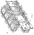
- Toner supply assembly 10 which includes the invention, here designated as toner hopper lockout mechanism 50.
- Toner supply assembly 10 includes four toner hoppers, yellow toner hopper 11, magenta toner hopper 12, cyan toner hopper 13 and black toner hopper 14.
- Each toner hopper is fitted with a cover 15 which prevents toner from spilling out of the hoppers and prevents objects from entering the hoppers.
- Each cover 15 is attached to its respective hopper by a cover slider 16, which is provided with a cover slider knob 17 to allow an operator to open and close covers 15 for refilling.
- Color electrographic printing toner supply assembly 10 is supported within the housing of a color image forming apparatus 25, which includes a dry toner developing means 26, usually employing a separate developer for each toner color, and an image retainer 27, such as a photoconducting drum.
- a drive shaft 18 is suspended below the toner hoppers and serves as a mechanism to transfer rotational power to the supply augers and mixing paddles, neither of which are shown but are located within each toner hopper.
- Each toner hopper has a corresponding clutch 19 and set of drive gears 20 located on drive shaft 18.
- Clutches 19 are independently activated by corresponding clutch tabs 22, located on a separate selector shaft 21.
- Selector shaft 21 is suspended in parallel spaced relation to drive shaft 18.
- Selector shaft 21 is used by the engine controller to activate the supply augers and mixing paddles within the individual toner hoppers.
- Clutch tabs 22 are mounted in angular spaced relation to one another at progressive 90° increments.
- each toner hopper clutch 19 is positioned to engage each toner hopper clutch 19, one at a time, in the order yellow, magenta, cyan, and black.
- the corresponding drive gear will turn and drive the supply auger and a hopper shaft, not shown.
- the hopper shaft turns stirring paddles inside the selected hopper body.
- Selector shaft 21 has a home position at which none of toner hopper clutches 19 are engaged. From this position, a rotation of 45° counterclockwise engages the yellow clutch, with subsequent rotations of 90° to engage the magenta clutch, the cyan clutch and the black clutch, and finally 45° to return to the home position.
- Toner hopper lockout mechanism 50 takes advantage of selector shaft 21, by using it to selectively lock out and unlock the individual toner hoppers.
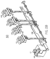
- Selector shaft 21 has a plurality of cams 100, one for each toner hopper, axially fixed on it. Cams 100 are positioned on selector shaft 21 so that each one interferes with the lower extremity of a cam follower member 102. There is one cam follower member 102 for each toner hopper. Each cam follower member 102 is slidably attached to a support plate 121 which is fixed on the front side of toner supply assembly 10. Cam follower members 102 are slidable up and down between an upward lockout position and a downward refill position.
- a stationary pin 127 and bushing 125 act to slidably secure each cam follower member 102 to support plate 121 by engaging the lower oval opening 104 of each cam follower member 102.
- Stationary pin 127 and bushing 125 are also configured to allow a small angular displacement of each follower member 102, as is shown in Fig. 3D.
- the upper oval opening 104 receives spring bushing assembly 122.
- spring 107 and washer 128 are positioned about stationary pin 124 and bushing 106, between cam follower member 102 and the flange around the head of stationary pin 124.
- Stationary pin 124 is fixed to support plate 121. This configuration allows a lateral angular displacement of cam follower members 102, explained more thoroughly below.
- Each cam follower member 102 also has a follower tip 103 extending from its upper end and a slider follower pin 105 extending generally perpendicularly from its lower midsection.
- follower tips 103 are positioned to engage the under side of their corresponding lockout members 112, which are also described below.
- Each slider follower pin 105 on the individual cam follower members 102 is engaged in an inclined follower notch 109 in slider member 108.
- Slider member 108 spans across all four cam follower members 102. Sideways motion of slider member 108 will either lock all four cam follower members 102 in their upward locked position, or will allow follower members 102 to be pushed down to rest on cams 100.
- a torsion spring about the pivot attachment point between each lockout member 112 and toner the individual toner hoppers acts to push cam follower members 102 down when slider member 108 is in the unlocked position.
- Slider member 108 is controlled by a double action solenoid 111.
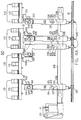
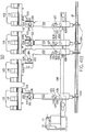
- An upwards motion of solenoid 111 will move slider member 108 from left to right, as is shown in Fig. 4A, while a downward motion of solenoid 111 will move slider member 108 from right to left, as is shown in Fig. 4B.
- the transfer of motion from the up and down motion of the solenoid to the sideways motion of the slider member is accomplished by idler arm 110.
- Idler arm 110 pivots about a stationary point on support plate 121.
- each follower member 102 is configured to ride on cams 100.
- Selector shaft 21 is only rotated when slider member 108 is in the locked out position as cams 100 are not intended to provide lifting force.
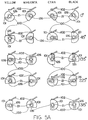
- Each cam 100 has a lobe portion 101, which will result in that particular toner hopper being locked out, and a flat portion 126, which will result in that particular toner hopper being unlocked so a toner cartridge 24 can be attached to the top of the toner hopper.
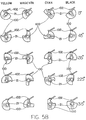
- a second embodiment of the cam configuration is illustrated in Figure 5B.
- the first row of cams 100 across the top of that Figure illustrates a position of the selector shaft in which all toner hoppers are in their refill states. This allows for convenient filling of all the toner hoppers immediately after purchase by the consumer.
- Each lockout member 112 is pivotally attached to its individual hopper to pivot between a locked out position which has lockout members 112 in a generally upright position, and a refill position which has lockout members 112 in a reclined position out of the way of the toner hopper and corresponding toner cartridge 24.
- Lockout members 112 have a claw-shaped configuration and when they are positioned in their locked out positions, fingers 113 of each member 112 will interfere with a connection between toner bottle or cartridge 24 and the particular toner hopper. This interference will prevent toner cartridge 24 from being snapped on to the locked out toner hopper.
- the cam follower member corresponding to the empty toner hopper will be pushed down to its refill position, allowing lockout member 112 to pivot away from the top of the toner hopper.
- toner cartridge 24 can be engaged with key system 23, located along the back edge of each toner hopper lid. Once engaged with key system 23, the toner cartridge base is then snapped down and held in place by a resilient latch 115.
- the base of toner cartridge 24 also engages a toner cartridge interlock latch 120 which allows the cover to be opened only when a cartridge is installed.
- Each hopper is equipped with a piezoelectric transducer 119 which is configured to sense an empty condition inside its respective toner hopper.
- piezoelectric transducer 119 signals the engine controller, which in turn displays a message on the front panel of the device to notify the operator of the empty condition.
- piezoelectric transducer 119 will sense the presence of toner and communicate this condition to the engine controller. The engine controller will then activate solenoid 111 causing cam follower members 102 to be slid upwards into their locked positions.
- the sequence for adding toner is as follows. During normal operation, one of the toner hoppers will become empty. For this example, assume that magenta hopper 12 is empty. When this happens a message is displayed on the front panel to add magenta toner. As long as the printer is idle, none of toner hoppers can have a toner cartridge 24 connected because slider member 108 is in the locked position.
- the operator indicates, by pressing a front panel key, that he or she wishes to add magenta toner to the system.
- the engine controller will first verify that magenta toner hopper 12 is empty. If it is, the controller will rotate selector shaft 21 to the magenta clutch engagement position, thus engaging both magenta clutch 19 and rotating magenta cam 100 to its refill position. The engine will not, however, engage drive shaft 18, so that engaging magenta clutch 19 has no effect. Since the lobe 101 of magenta cam 100 is not in a position to support cam follower member 102, cam follower member 102 will be pushed down, causing lockout member 112 to pivot into its refill position.
- lockout member 112 Once lockout member 112 is in its refill position, the operator can snap toner cartridge 24 into position on toner hopper 12, engaging the base of the toner cartridge with cover interlock latch 120. The operator then is able to open cover 15, via cover slider knob 17, and drain toner cartridge 24. Immediately upon sensing that magenta toner hopper 12 has new toner, the engine controller will return slider member 108 to the locked out position forcing cam follower member 102 up so that lockout member 112 is spring biased against the base of toner cartridge 24. When the operator removes toner cartridge 24, lockout member 112 will pivot into its closed position.
Landscapes
- Physics & Mathematics (AREA)
- General Physics & Mathematics (AREA)
- Dry Development In Electrophotography (AREA)
- Electrophotography Configuration And Component (AREA)
- Control Or Security For Electrophotography (AREA)
Applications Claiming Priority (2)
| Application Number | Priority Date | Filing Date | Title |
|---|---|---|---|
| US306049 | 1981-09-25 | ||
| US08/306,049 US5610692A (en) | 1994-09-14 | 1994-09-14 | Toner hopper lockout mechanism |
Publications (3)
| Publication Number | Publication Date |
|---|---|
| EP0702281A2 true EP0702281A2 (fr) | 1996-03-20 |
| EP0702281A3 EP0702281A3 (fr) | 1996-06-19 |
| EP0702281B1 EP0702281B1 (fr) | 1999-08-04 |
Family
ID=23183534
Family Applications (1)
| Application Number | Title | Priority Date | Filing Date |
|---|---|---|---|
| EP95106129A Expired - Lifetime EP0702281B1 (fr) | 1994-09-14 | 1995-04-24 | Mécanisme de blocage pour un réservoir de distribution de toner |
Country Status (4)
| Country | Link |
|---|---|
| US (2) | US5610692A (fr) |
| EP (1) | EP0702281B1 (fr) |
| JP (1) | JP3860853B2 (fr) |
| DE (1) | DE69511194T2 (fr) |
Cited By (1)
| Publication number | Priority date | Publication date | Assignee | Title |
|---|---|---|---|---|
| EP0686892A3 (fr) * | 1994-06-07 | 1997-07-30 | Konishiroku Photo Ind | Appareil de formation d'images muni d'un dispositif de remplissage de toner |
Families Citing this family (18)
| Publication number | Priority date | Publication date | Assignee | Title |
|---|---|---|---|---|
| US5610692A (en) * | 1994-09-14 | 1997-03-11 | Hewlett-Packard Company | Toner hopper lockout mechanism |
| KR100307584B1 (ko) * | 1998-02-27 | 2001-12-12 | 윤종용 | 습식전자사진방식인쇄기용잉크공급장치 |
| US6006046A (en) * | 1998-03-19 | 1999-12-21 | Troy Systems, Inc. | Policing key for a toner consuming machine |
| US6591077B2 (en) * | 2000-05-08 | 2003-07-08 | Ricoh Company, Ltd. | Image forming apparatus and toner container therefor |
| US6438328B1 (en) | 2000-11-08 | 2002-08-20 | Xerox Corporation | Reversible shutter lockout feature |
| JP3663542B2 (ja) * | 2002-01-23 | 2005-06-22 | 京セラ株式会社 | 画像形成機のトナー供給容器 |
| JP4035384B2 (ja) * | 2002-06-19 | 2008-01-23 | キヤノン株式会社 | 現像剤補給容器 |
| US6961531B2 (en) | 2002-10-17 | 2005-11-01 | Hewlett-Packard Development Company, L.P. | Refillable print cartridge and method of refilling |
| US6778801B1 (en) | 2003-04-07 | 2004-08-17 | Hewlett-Packard Development Company, L.P. | Image-forming device and method with adjustable toner chamber cavity |
| JP5414386B2 (ja) * | 2009-06-29 | 2014-02-12 | キヤノン株式会社 | 画像形成装置及びその方法 |
| JP6493278B2 (ja) * | 2016-03-31 | 2019-04-03 | 京セラドキュメントソリューションズ株式会社 | 画像形成装置、現像剤収容部の交換規制の解除方法 |
| US11073784B2 (en) | 2018-03-29 | 2021-07-27 | Hewlett-Packard Development Company, L.P. | Print supply locks |
| KR20190124555A (ko) | 2018-04-26 | 2019-11-05 | 휴렛-팩커드 디벨롭먼트 컴퍼니, 엘.피. | 토너의 리필 동작을 가이드 하는 화상 형성 장치 |
| USD918972S1 (en) * | 2018-08-01 | 2021-05-11 | Panasonic Intellectual Property Management Co. Ltd | Laser resonator |
| USD908751S1 (en) * | 2018-08-01 | 2021-01-26 | Panasonic Intellectual Property Management Co. Ltd | Laser engine with multiple resonators |
| USD908148S1 (en) * | 2018-08-01 | 2021-01-19 | Panasonic Intellectual Property Management Co. Ltd | Laser engine with multiple resonators |
| USD1040203S1 (en) * | 2020-04-30 | 2024-08-27 | Raylase Gmbh | Mirror-symmetric laser module |
| KR20230025985A (ko) * | 2021-08-17 | 2023-02-24 | 휴렛-팩커드 디벨롭먼트 컴퍼니, 엘.피. | 토너 리필 카트리지를 장착부로부터 팝업시키는 구조 |
Family Cites Families (12)
| Publication number | Priority date | Publication date | Assignee | Title |
|---|---|---|---|---|
| JPH0695245B2 (ja) * | 1985-01-24 | 1994-11-24 | 三田工業株式会社 | トナ−カ−トリツジの着脱機構 |
| US5184181A (en) * | 1986-09-24 | 1993-02-02 | Mita Industrial Co., Ltd. | Cartridge discriminating system |
| JPS63220287A (ja) * | 1987-03-10 | 1988-09-13 | Ricoh Co Ltd | 現像装置 |
| US4878091A (en) * | 1987-09-17 | 1989-10-31 | Konica Corporation | Multicolor image forming apparatus |
| JPH01142764A (ja) * | 1987-11-30 | 1989-06-05 | Toshiba Corp | 画像形成装置 |
| JPH0466982A (ja) * | 1990-07-04 | 1992-03-03 | Mita Ind Co Ltd | トナー補給装置 |
| JPH0552863U (ja) * | 1991-12-18 | 1993-07-13 | 株式会社リコー | 現像ユニット等及びトナーカートリッジの着脱機構 |
| US5392102A (en) * | 1992-05-26 | 1995-02-21 | Konica Corporation | Developing device having toner cartridge discriminator |
| US5313993A (en) * | 1992-12-03 | 1994-05-24 | Eastman Kodak Company | Toner container and receiving apparatus therefor |
| JPH06250522A (ja) * | 1992-12-28 | 1994-09-09 | Canon Inc | 現像装置及びこの現像装置に着脱される現像剤補給カートリッジ |
| US5430531A (en) * | 1992-12-28 | 1995-07-04 | Canon Kabushiki Kaisha | Locking apparatus for toner cartridge |
| US5610692A (en) * | 1994-09-14 | 1997-03-11 | Hewlett-Packard Company | Toner hopper lockout mechanism |
-
1994
- 1994-09-14 US US08/306,049 patent/US5610692A/en not_active Expired - Lifetime
-
1995
- 1995-04-24 EP EP95106129A patent/EP0702281B1/fr not_active Expired - Lifetime
- 1995-04-24 DE DE69511194T patent/DE69511194T2/de not_active Expired - Fee Related
- 1995-09-14 JP JP26220495A patent/JP3860853B2/ja not_active Expired - Fee Related
-
1996
- 1996-10-22 US US08/734,933 patent/US5802435A/en not_active Expired - Lifetime
Cited By (1)
| Publication number | Priority date | Publication date | Assignee | Title |
|---|---|---|---|---|
| EP0686892A3 (fr) * | 1994-06-07 | 1997-07-30 | Konishiroku Photo Ind | Appareil de formation d'images muni d'un dispositif de remplissage de toner |
Also Published As
| Publication number | Publication date |
|---|---|
| DE69511194D1 (de) | 1999-09-09 |
| JPH0887176A (ja) | 1996-04-02 |
| EP0702281B1 (fr) | 1999-08-04 |
| JP3860853B2 (ja) | 2006-12-20 |
| DE69511194T2 (de) | 2000-03-09 |
| EP0702281A3 (fr) | 1996-06-19 |
| US5802435A (en) | 1998-09-01 |
| US5610692A (en) | 1997-03-11 |
Similar Documents
| Publication | Publication Date | Title |
|---|---|---|
| EP0702281B1 (fr) | Mécanisme de blocage pour un réservoir de distribution de toner | |
| KR100878377B1 (ko) | 현상제 공급 용기 및 화상 형성 장치 | |
| CA2854353C (fr) | Cartouche de toner ayant un mecanisme de verrou d'obturateur | |
| EP2237112B1 (fr) | Corps de stockage de révélateur, unité de formation d'images et appareil de formation d'images | |
| KR20080077922A (ko) | 현상제 공급 케이스 및 화상 형성 장치 | |
| JPH05204244A (ja) | 画像形成装置 | |
| CN107329386B (zh) | 图像形成装置、锁定装置和锁定单元 | |
| US4650097A (en) | Developer material supply arrangement | |
| JP3672067B2 (ja) | 画像形成装置 | |
| RU2433441C2 (ru) | Накопитель средств формирования изображений и устройство формирования изображений | |
| CN100511005C (zh) | 调色剂补给容器及成像装置 | |
| US20150016847A1 (en) | Toner container and image forming apparatus including the toner container | |
| US9329527B2 (en) | Toner case and image forming apparatus including the same | |
| US9261850B2 (en) | Image forming apparatus and collecting container | |
| US9625871B2 (en) | Image forming apparatus to which toner container is attachable | |
| JP2024065178A (ja) | トナーコンテナ、画像形成装置 | |
| JP6053705B2 (ja) | 画像形成装置 | |
| CN108323188B (zh) | 显影剂收容容器以及具备该显影剂收容容器的图像形成装置 | |
| JP6021834B2 (ja) | トナー搬送装置、及びこれを備える画像形成装置 | |
| CN112930500B (zh) | 图像形成装置 | |
| JP4568057B2 (ja) | トナーコンテナ | |
| EP4610738A1 (fr) | Appareil de formation d'images | |
| JP7624362B2 (ja) | 画像形成装置 | |
| JP2021015237A (ja) | 現像剤補給装置、及び、画像形成装置 | |
| JPH09134075A (ja) | 画像形成装置 |
Legal Events
| Date | Code | Title | Description |
|---|---|---|---|
| PUAI | Public reference made under article 153(3) epc to a published international application that has entered the european phase |
Free format text: ORIGINAL CODE: 0009012 |
|
| AK | Designated contracting states |
Kind code of ref document: A2 Designated state(s): DE FR GB IT |
|
| PUAL | Search report despatched |
Free format text: ORIGINAL CODE: 0009013 |
|
| AK | Designated contracting states |
Kind code of ref document: A3 Designated state(s): DE FR GB IT |
|
| RAP1 | Party data changed (applicant data changed or rights of an application transferred) |
Owner name: KONICA CORPORATION Owner name: HEWLETT-PACKARD COMPANY |
|
| 17P | Request for examination filed |
Effective date: 19960920 |
|
| 17Q | First examination report despatched |
Effective date: 19980813 |
|
| GRAG | Despatch of communication of intention to grant |
Free format text: ORIGINAL CODE: EPIDOS AGRA |
|
| GRAG | Despatch of communication of intention to grant |
Free format text: ORIGINAL CODE: EPIDOS AGRA |
|
| GRAG | Despatch of communication of intention to grant |
Free format text: ORIGINAL CODE: EPIDOS AGRA |
|
| GRAH | Despatch of communication of intention to grant a patent |
Free format text: ORIGINAL CODE: EPIDOS IGRA |
|
| GRAH | Despatch of communication of intention to grant a patent |
Free format text: ORIGINAL CODE: EPIDOS IGRA |
|
| GRAA | (expected) grant |
Free format text: ORIGINAL CODE: 0009210 |
|
| AK | Designated contracting states |
Kind code of ref document: B1 Designated state(s): DE FR GB IT |
|
| REF | Corresponds to: |
Ref document number: 69511194 Country of ref document: DE Date of ref document: 19990909 |
|
| ET | Fr: translation filed | ||
| PLBE | No opposition filed within time limit |
Free format text: ORIGINAL CODE: 0009261 |
|
| STAA | Information on the status of an ep patent application or granted ep patent |
Free format text: STATUS: NO OPPOSITION FILED WITHIN TIME LIMIT |
|
| 26N | No opposition filed | ||
| REG | Reference to a national code |
Ref country code: GB Ref legal event code: IF02 |
|
| PGFP | Annual fee paid to national office [announced via postgrant information from national office to epo] |
Ref country code: DE Payment date: 20080602 Year of fee payment: 14 |
|
| PGFP | Annual fee paid to national office [announced via postgrant information from national office to epo] |
Ref country code: IT Payment date: 20080429 Year of fee payment: 14 |
|
| PGFP | Annual fee paid to national office [announced via postgrant information from national office to epo] |
Ref country code: FR Payment date: 20080417 Year of fee payment: 14 |
|
| PGFP | Annual fee paid to national office [announced via postgrant information from national office to epo] |
Ref country code: GB Payment date: 20080429 Year of fee payment: 14 |
|
| GBPC | Gb: european patent ceased through non-payment of renewal fee |
Effective date: 20090424 |
|
| REG | Reference to a national code |
Ref country code: FR Ref legal event code: ST Effective date: 20091231 |
|
| PG25 | Lapsed in a contracting state [announced via postgrant information from national office to epo] |
Ref country code: DE Free format text: LAPSE BECAUSE OF NON-PAYMENT OF DUE FEES Effective date: 20091103 |
|
| PG25 | Lapsed in a contracting state [announced via postgrant information from national office to epo] |
Ref country code: GB Free format text: LAPSE BECAUSE OF NON-PAYMENT OF DUE FEES Effective date: 20090424 Ref country code: FR Free format text: LAPSE BECAUSE OF NON-PAYMENT OF DUE FEES Effective date: 20091222 |
|
| PG25 | Lapsed in a contracting state [announced via postgrant information from national office to epo] |
Ref country code: IT Free format text: LAPSE BECAUSE OF NON-PAYMENT OF DUE FEES Effective date: 20090424 |