EP0702283B1 - Doppelseitenbilderzeugungsgerät mit Nachbearbeitungsfunktion - Google Patents
Doppelseitenbilderzeugungsgerät mit Nachbearbeitungsfunktion Download PDFInfo
- Publication number
- EP0702283B1 EP0702283B1 EP95112685A EP95112685A EP0702283B1 EP 0702283 B1 EP0702283 B1 EP 0702283B1 EP 95112685 A EP95112685 A EP 95112685A EP 95112685 A EP95112685 A EP 95112685A EP 0702283 B1 EP0702283 B1 EP 0702283B1
- Authority
- EP
- European Patent Office
- Prior art keywords
- transport path
- image forming
- sheets
- sheet
- forming apparatus
- Prior art date
- Legal status (The legal status is an assumption and is not a legal conclusion. Google has not performed a legal analysis and makes no representation as to the accuracy of the status listed.)
- Expired - Lifetime
Links
Images







Classifications
-
- G—PHYSICS
- G03—PHOTOGRAPHY; CINEMATOGRAPHY; ANALOGOUS TECHNIQUES USING WAVES OTHER THAN OPTICAL WAVES; ELECTROGRAPHY; HOLOGRAPHY
- G03G—ELECTROGRAPHY; ELECTROPHOTOGRAPHY; MAGNETOGRAPHY
- G03G15/00—Apparatus for electrographic processes using a charge pattern
- G03G15/65—Apparatus which relate to the handling of copy material
- G03G15/6538—Devices for collating sheet copy material, e.g. sorters, control, copies in staples form
- G03G15/6541—Binding sets of sheets, e.g. by stapling, glueing
-
- G—PHYSICS
- G03—PHOTOGRAPHY; CINEMATOGRAPHY; ANALOGOUS TECHNIQUES USING WAVES OTHER THAN OPTICAL WAVES; ELECTROGRAPHY; HOLOGRAPHY
- G03G—ELECTROGRAPHY; ELECTROPHOTOGRAPHY; MAGNETOGRAPHY
- G03G15/00—Apparatus for electrographic processes using a charge pattern
- G03G15/22—Apparatus for electrographic processes using a charge pattern involving the combination of more than one step according to groups G03G13/02 - G03G13/20
- G03G15/23—Apparatus for electrographic processes using a charge pattern involving the combination of more than one step according to groups G03G13/02 - G03G13/20 specially adapted for copying both sides of an original or for copying on both sides of a recording or image-receiving material
- G03G15/231—Arrangements for copying on both sides of a recording or image-receiving material
- G03G15/232—Arrangements for copying on both sides of a recording or image-receiving material using a single reusable electrographic recording member
- G03G15/234—Arrangements for copying on both sides of a recording or image-receiving material using a single reusable electrographic recording member by inverting and refeeding the image receiving material with an image on one face to the recording member to transfer a second image on its second face, e.g. by using a duplex tray; Details of duplex trays or inverters
-
- G—PHYSICS
- G03—PHOTOGRAPHY; CINEMATOGRAPHY; ANALOGOUS TECHNIQUES USING WAVES OTHER THAN OPTICAL WAVES; ELECTROGRAPHY; HOLOGRAPHY
- G03G—ELECTROGRAPHY; ELECTROPHOTOGRAPHY; MAGNETOGRAPHY
- G03G2215/00—Apparatus for electrophotographic processes
- G03G2215/00362—Apparatus for electrophotographic processes relating to the copy medium handling
- G03G2215/00535—Stable handling of copy medium
- G03G2215/00556—Control of copy medium feeding
- G03G2215/00586—Control of copy medium feeding duplex mode
-
- G—PHYSICS
- G03—PHOTOGRAPHY; CINEMATOGRAPHY; ANALOGOUS TECHNIQUES USING WAVES OTHER THAN OPTICAL WAVES; ELECTROGRAPHY; HOLOGRAPHY
- G03G—ELECTROGRAPHY; ELECTROPHOTOGRAPHY; MAGNETOGRAPHY
- G03G2215/00—Apparatus for electrophotographic processes
- G03G2215/00362—Apparatus for electrophotographic processes relating to the copy medium handling
- G03G2215/00789—Adding properties or qualities to the copy medium
- G03G2215/00822—Binder, e.g. glueing device
- G03G2215/00827—Stapler
Definitions
- the present invention relates to an image forming apparatus, such as a copying apparatus having sheet post-processing function for performing a post-process, such as a stapling process, on sheets where an image has been formed and a double-side image forming function for forming an image on both sides of sheets.
- a post-process such as a stapling process
- an image forming apparatus such as a copying apparatus
- an intermediate tray is provided inside the apparatus and an image is formed on both sides of sheets by using the intermediate tray.
- the sheet is again carried to an image forming section so that an image is formed on the other side of the sheet.
- a post-processing unit such as a stapler for stapling a plurality of sheets where images have been formed on one side or both sides.
- the intermediate tray and the stapler which are used for such a double-side image forming process, requires common processes, such as a sheet adjusting process, a process for stacking a plurality of sheets.
- common processes such as a sheet adjusting process, a process for stacking a plurality of sheets.
- mechanisms for common processes are duplicated.
- the apparatus becomes large and a number of parts increases, thereby causing a rise in costs.
- a double-side image forming apparatus having a post-processing function of the present invention includes (1) a sheet storing section for storing and feeding sheets, (2) an image forming section for forming an image on sheets, (3) a feed transport path which extends from the sheet storing section to the image forming section, (4) a first discharge section for discharging sheets out of the apparatus which is opened on one side of the double-side image forming apparatus, (5) a second discharge section for discharging sheets out of the apparatus which is opened on the same side where the first discharge section is formed, (6) a first transport path which extends from the image forming section to the first discharge section, (7) a second transport path for reversing a front and rear of a sheet transporting direction which includes a sheet insertion/discharge opening connected to a first discharge section side of the first transport path, (8) a third transport path having a sheet insertion opening and a sheet discharge opening, the sheet insertion opening being connected to the sheet insertion/discharge opening of the
- the post-process such as a stapling process
- a sheet adjusting process and sheet stacking for the post, process in the fourth transport path, and a sheet adjusting process and sheet stacking in the second transport path which is used for reversing a front/rear direction of sheets at the time of double-side image forming are carried out by common adjusting means.
- the double-side image forming apparatus of the present invention requires only one adjusting means, so the apparatus can be miniaturized by decreasing space for arrangement of the adjusting means and costs of the apparatus can be lowered by decreasing a number of parts.
- the second discharge section for discharging post-processed sheets is formed on the same side of the apparatus as the side where the first discharge section for discharging not post-processed sheets is formed. Therefore, the sheets, which have been subject to the post-process by means of the post-processing means in the fourth transport path, are discharged to the same side as that where the not post-processed sheets are discharged. As a result, even in the case where an image forming process which performs the post-process on the sheets and an image forming process which does not perform the post-process on the sheets are continuously executed, there does not occur remaining of sheets. Moreover, in the case where a discharge tray is provided in the first and second discharge sections, these two discharge trays are projected in a same direction, so the image forming apparatus can be miniaturized compared to the case where the discharge trays are projected in opposite directions.
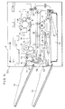
- Fig. 1 is a front view which shows an internal structure of a double-side image forming apparatus of one embodiment according to the present invention.
- Fig. 2 is a enlarged drawing which shows a main part of the double-side image forming apparatus shown in Fig. 1.
- Fig. 3 is a perspective view which shows a stapler provided in the double-side image forming apparatus.
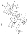
- Fig. 4 is a perspective view which shows an adjusting unit provided in the double-side image forming apparatus.
- Fig. 5 is a perspective view which shows a transporting path unit provided in the double-side image forming apparatus.
- Fig. 6 is a block diagram which shows an arrangement of a control section of the double-side image forming apparatus shown in Fig. 1.
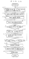
- Fig. 7 is a flow chart which shows a processing procedure in an one-side image forming mode which does not perform a stapling process in the double-side image forming apparatus.
- Fig. 8 is a flow chart which shows a processing procedure in an one-side image forming mode which performs the stapling process in the double-side image forming apparatus.
- Fig. 9 is a flow chart which shows a processing procedure in a double-side image forming mode which does not perform the stapling process in the double-side image forming apparatus.
- Fig. 10 is a flow chart which shows a processing procedure in a double-side image forming mode which performs the stapling process in the double-side image forming apparatus.
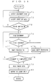
- Fig. 11 is a flow chart which shows a processing procedure for setting a staple position at the time of the stapling process in the double-side image forming apparatus.
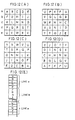
- Fig. 12(A) is an explanatory drawing which shows image data which have been read by the double-side image forming apparatus.
- Fig. 12(B) is an explanatory drawing which shows a state that the image data in a state shown in Fig. 12(A) is rotated through an angle of 90°.
- Fig. 12(C) is an explanatory drawing which shows a state that the image data in the state shown in Fig. 12(A) is rotated through an angle of 180°.
- Fig. 12(D) is an explanatory drawing which shows a state that the image data in the state shown in Fig. 12(A) is rotated through an angle of 270°.
- Fig. 12(E) is an explanatory drawing which shows a storing state of image data which have been read by the double-side image forming apparatus in RAM shown in Fig. 6.
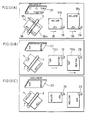
- Fig. 13(A) is an explanatory drawing of a stapling process in the case where an image is formed with an up-and-down direction of a document intersecting perpendicularly to a sheet transporting direction in the double-side image forming apparatus.
- Fig. 13(B) is an explanatory drawing in the case where the stapling process is faulty when an image is formed with an up-and-down direction of a document being coincide with the sheet transporting direction in the double-side image forming apparatus.
- Fig. 13(C) is an explanatory drawing which shows an excellent stapling process in the case of Fig. 13(B).
- Fig. 14 is a front view which shows an internal structure of a double-side image forming apparatus of another embodiment according to the present invention.
- Fig. 15 is an enlarged drawing which shows a main section of the double-side image forming apparatus shown in Fig. 14.
- Fig. 16 is a flow chart which shows a processing procedure in an one-side image forming mode which performs a stapling process in the double-side image forming apparatus shown in Fig. 14.
- Fig. 17 is a flow chart which shows a processing procedure in a double-side image forming mode which does not perform the stapling process in the double-side image forming apparatus shown in Fig. 14.
- Fig. 18 is a flow chart which shows a processing procedure in the double-side image forming mode which performs the stapling process in the double-side image forming apparatus shown in Fig. 14.
- Fig. 19 is a front view which shows an internal structure of a double-side image forming apparatus which is a prerequisite for the double-side image forming apparatus shown in Fig. 1.
- the applicant of the present invention suggested an image forming apparatus 201 shown in Fig. 19 in Japanese Patent Application No. 4-94206/1992 (Tokuganhei 4-94206).
- the image forming apparatus 201 is provided with a stapler 203 in an intermediate tray 202 which is used for a double-side image forming process.
- sheets where an image has been formed on their one side by an image forming section 206 are discharged on a discharge tray 204 through a transport path 207.
- the sheets where an image has been formed on their one side by the image forming section 206 are transported to the intermediate tray 202 through the transport path 207, a transport path 208, a switch back transport path 209 and a transport path 210, and the sheets are adjusted with a prescribed position of the intermediate tray 202.
- the sheets are again transported to the image forming section 206 through a transport path 211 and after an image is formed on opposite sides of the sheets, the sheets are discharged on the discharge tray 204.
- sheets on which an image has been formed are stored on the intermediate tray 202 and are adjusted by a jogger 212. Thereafter, the sheets are stapled by the stapler and are discharged on a discharge tray 205.
- the above image forming apparatus 201 is provided with the stapler 203 in the intermediate tray 202, a mechanism for a sheet adjusting process and a mechanism for a sheet stacking process at the time of the stapling process and of the both-side image forming are one and the same. This makes it possible to miniaturize the image forming apparatus 201 by reducing an arrangement space and to realize lowering of costs by reducing a number of parts.
- the image forming apparatus 201 can utilize reverse transport means which is indispensable to the both-side image forming process, namely, a reverse transport path 209 and the intermediate tray 202.
- the image forming apparatus 201 is provided with the discharge tray 205 on a right side of the image forming apparatus 201 besides the discharge tray 204 provided on a left side of the image forming apparatus 201.
- the intermediate tray 202 having the stapler 203 is provided such that the right side of the image forming apparatus 201 is opened.
- the sheets, which have been subject to the stapling process on the intermediate tray 202, are discharged to the discharge tray 205 on the right side. For this reason, the sheets are discharged to the both sides of the image forming apparatus 201.
- the discharge tray 204 and the discharge tray 205 are projected on one side and the other side of the image forming apparatus 201. Therefore, there's a limit in miniaturizing the apparatus.
- an image forming apparatus 1 has an optical unit 2 on its upper side.
- the optical unit 2 reads an image of a document and converts its image information to digital data.
- a photoreceptor drum 3, a charger 4, a developing unit 5, a transfer charger 6, a peeling charger 7, a cleaning unit 8 and a charge eliminating lamp 9 which compose an image forming section 10 are provided inside the image forming apparatus 1.
- the charger 4, the developing unit 5, the transfer charger 6, the peeling charger 7, the cleaning unit 8 and the charge eliminating lamp 9 are positioned on a periphery of the photoreceptor drum 3.
- a transport belt 11 and a discharge roller 24 are provided from the image forming section through a fixing unit 12 to a discharge tray 15, and they composes a first transport path 14 including a discharge transport path 16.
- An end of the discharge roller 24 is a first discharge section which is provided on the side of the image forming apparatus 1 so that the side is opened.
- a sheet cassette 25 is attached at the inner bottom of the image forming apparatus 1.
- the sheet cassette 25 houses a prescribed number of sheets, and it is detachable from a front side of the image forming apparatus 1.
- a feed transport path 43 is provided between the sheet cassette 25 and the image forming section 10 in an inner right part of the image forming apparatus 1.
- a PS roller 36 is provided to the feed transport path 43. The PS roller 36 synchronizes with a rotation of the photoreceptor drum 3 so as to lead sheets, which have been supplied from the sheet cassette 25 by a feeding roller 26, to the image forming section 10.
- a second transport path 17, a third transport path 18 and a fourth transport path 19 are positioned between the first transport path 14 and the sheet cassette 25 such that they are layered almost horizontally and parallel with one another.
- a sheet insertion/discharge opening of the second transport path 17 is connected to the discharge transport path 16 side of the first transport path 14 through a passage 37 as a first connecting passage.
- a flapper 20 as first guiding means which freely rocks is provided to a section where the passage 37 and the first transport path 14 join. The flapper 20 selectively leads sheets which have passed the fixing unit 12 to the discharge transport path 16 or the passage 37.
- a switch back roller 23 is provided in a proximity of the sheet insertion/discharge opening of the second transport path 17. The switch back roller 23 rotates in one direction and in its reverse direction, and inverts a sheet transporting direction.
- the third transport path 18 connects the sheet insertion/discharge opening of the second transport path 17 to the feed transport path 43.
- the fourth transport path 19 is provided with a sheet insertion opening which is connected to the sheet insertion/discharge opening of the second transport path 17.
- the fourth transport path 19 contains a paddler 27, a jogger 28, a stapler 29 and a pusher 31.
- the paddler 27 is provided with a plurality of flexible pressure plates on its circumferential surface, and it rotates counterclockwise so that a forward end of a sheet contacts with the pusher 31.
- the jogger 28 adjusts sheets with a prescribed position in a direction which intersects perpendicularly to the sheet transporting direction.
- the sheet insertion/discharge opening of the second transport path 17 is connected to the discharge transport path 16 through a face down transport path 21 which is a fifth transport path. Moreover, the sheet insertion/discharge opening is connected to the sheet insertion openings of the third transport path 18 and the fourth transport path 19 through a passage 61 as a second connecting passage.
- the face down transport path 21 inverts front and back faces of a sheet on which an image has been formed so as to discharge it.
- the face down transport path 21 is provided to a position of the discharge tray 15 side with respect to the passage 37 such as to stretch in an up-and-down direction. This makes it possible to easily arrange the face down transport path 21 without enlarging of the apparatus.
- a flapper 22 as second guiding means is provided between the face down transport path 21 and the sheet insertion/discharge openings of the second transport path 17.
- the flapper 22 leads sheets to be discharged from the second transport path 17 towards the face down transport path 21 or the third and fourth transport paths 18 and 19.
- a flapper 42 as third guiding means is provided to the sheet insertion openings of the third transport path 18 and the fourth transport path 19.
- the flapper 42 leads sheets, which have been led downward from the second transport path 17 through the passage 61, to the third transport path 18 or the fourth transport path 19.
- a rotating plate 40 as a rocking member which freely rocks is provided in a midway position of the fourth transport path 19.
- the rotating plate 40 selectively connects the midway position of the fourth transport path 19 to the sheet insertion opening or a sixth transport path 30.
- the sixth transport path 30 is arranged between the midway position of the fourth transport path 19 and a discharge tray 34, and a discharge belt 33 is provided in a proximity of the discharge tray 34.
- An end section of the discharge belt 33 is a second discharge section which is opened to a side of the image forming apparatus 1.
- the rotating plate 40 can discharge a sheet which has been subject to a post-process, namely, a stapling process in an upper space of the sheet cassette 25. Therefore, the provision of the rotating plate 40 prevents enlargement of the apparatus.
- a charge eliminating member 41 is provided to the sheet insertion/discharge opening of the second transport path 17.
- the charge eliminating member 41 contacts with a sheet so as to eliminate charges from the sheet at the time of inserting and discharging the sheet in and from the second transport path 17.
- a straightening member 38 is provided in a proximity of the sheet insertion openings of the third transport path 18 and the fourth transport path 19. The straightening member 38 straightens curl of a sheet, which has been caused when the sheet has passed the fixing unit 12, etc.
- Fig. 3 is a drawing of an appearance of a stapler as post-processing means which is provided to the image forming apparatus.
- the stapler 29 is composed of a stapler main body 50 containing staples, a driving table 56, a motor M2, a gear 58 and a rocking system 59.
- the main body 50 contains a plate which drives staples into sheets, and the plate rocks in an up-and-down direction with respect to the main body 50. Moreover, the main body 50 freely rocks perpendicularly with respect to the driving table 56.
- the rocking system 59 makes the plate rock with respect to the main body 50 and makes the main body 50 with respect to the driving table 56.
- the rocking system 59 receives a supply of driving force from the motor M2 through the gear 58.
- a a feed screw 54 is screwed in a lower face of the stapler 29, and it contacts with a guide 53. Rotation of a motor 51 is supplied to the feed screw 54 through a gear 55.
- the stapler 29 moves back and forth along a guide 53 in a direction which intersects perpendicularly to the sheet transporting direction by rotation of the feed screw 54.
- the stapler 29 in a home position is detected by a sensor 52 which is opposite to a portion of the driving table 56.
- Fig. 4 is a drawing of appearance of an adjusting unit 80 as adjusting means provided to the image forming apparatus.
- the adjusting unit 80 includes a pair of joggers 28 ⁇ 28 which are opposite to each other.
- the joggers 28 ⁇ 28 are arranged such that a lower side member 28a and an upper side member 28b are connected in up-and-down direction by a connecting section 28c.
- a rack 87 is fixed to bottom surfaces of the joggers 28 ⁇ 28, and a pinion 86 is engaged with the rack 87.
- Rotation of a motor M3 is transmitted to the pinion 86 through a gear 84 and a belt 85.
- home positions of the joggers 28 ⁇ 28 are detected by a sensor 89.
- the lower side member 28a of the jogger 28 contacts with a side which is parallel to the transporting direction of sheets stored in the fourth transport path 19.
- the upper side member 28b contacts with a side which is parallel to the transporting direction of sheets stored in the second transport path 17. Since the fourth transport path 19 and the second transport path 17 are substantially parallel to each other, the lower side member 28a and the upper side member 28b are provided so as to be substantially parallel to each other.
- the connecting section 28c is a portion which is opposite to the third transport path 18. In order to make an exposure range of the third transport path 18 which does not require an adjusting process as small as possible, a width of the transporting direction of the third transport path 18 is made narrow.
- the joggers 28 ⁇ 28 move in a direction which intersects perpendicularly to the sheet transporting direction whenever sheets do not pass through the third transport path 18.
- Fig. 5 is a drawing of appearance which shows a transport unit 39 of the image forming apparatus.
- a transport guide 73 composing the second transport path 17, a transport guide 74 composing the third transport path 18 and a transport guide 75 composing of the fourth transport path 19 are mounted in a backup member 72 together with an adjusting unit 80 including the jogger 28 and the stapler 29, and they compose a transport unit 39.
- the transport unit 39 is freely taken in and out of the image forming apparatus 1 from a front of the image forming apparatus by means of a rail member 71.
- removal of jam of sheets from each transport path, and maintenance and check, such as supply of staples to the stapler 29 can be easily performed with each transport path, the stapler 29, etc. exposed to the outside of the apparatus.
- Fig. 6 is a block diagram which shows an arrangement of a control section 110 of the image forming apparatus.
- the control section 110 of the image forming apparatus is arranged such that a motor driver 101, a clutch driver 102, a solenoid driver 103, a sensor controller 104, a panel controller 105 and a CPU 111 of the control section 110 of an optical unit 2 are connected to a CPU 100 including a ROM 107 and a RAM 108 through an interface 106.
- the CPU 100 generally controls each I/O equipment according to programs which have been previously written to the ROM 107 and puts data to be inputted/outputted in a prescribed memory area of the RAM 108.
- the motor driver 101 drives each motor provided in the image forming apparatus 1 according to driving data to be outputted from the CPU 100.
- the motor M1 for driving the photoreceptor drum 3 in the image forming section 10, the motor M2 provided in the stapler 29, the motor M3 provided in the adjusting unit 80, etc. are connected to the motor driver 101.
- a plurality of clutches are connected to the clutch driver 102, and the clutch driver 102 drives each clutch according to driving data outputted from the CPU 100.
- the clutches connected to the clutch driver 102 selectively transmit rotation of the motor M1 to rollers provided in each transport path.
- a plurality of solenoids are connected to the solenoid driver 103, and the solenoid driver 103 drives the solenoids according to driving data outputted from the CPU 100.
- the solenoids connected to the solenoid driver 103 actuate the flappers 20, 22 and 42, etc.
- a plurality of sensors are connected to the sensor controller 104. These sensors include a sensor for detecting a sheet in a prescribed position of each transport path, a sensor for detecting temperature of a fixing roller of the fixing unit 12, etc. Data detected by these sensors are inputted to the CPU 100 through the sensor controller 104.
- a display unit and a keyboard which compose an operation panel are connected to the panel controller 105.
- the panel controller 105 drives each display unit according to display data outputted from the CPU 100 and sends operation data on the keyboard to the CPU 100.
- the CPU 100 is connected to a CPU 111 which composes a control section 110 of the optical unit 2.
- the control section 110 of the optical unit 2 is arranged such that an image data input section 115, an image processing section 116 and an image data output section 117 are connected to the CPU 111 having a ROM 112 and a RAM 113 through an interface 114.
- the image data input section 115 binarizes image data of a document which have been read by a CCD 118 of the optical unit 2 and processes the image data using an error diffusion method while taking a histogram as digital data.
- the CCD 118 outputs an analog electrical signal according to each picture element mode of the image data.
- the digital electrical signal is compensated by MTF compensation, black/white compensation or gamma correction so as to be outputted to a histogram processing section as a digital signal with tone of 256 (8 bits).
- the histogram processing section creates density information from the digital signal and supplies the density information as picture element data to an error diffusion processing section.
- the error diffusion processing section converts the digital signal of 8 bits/picture element into 1 bit (binary digit) using the error diffusion method which is a kind of a pseudo-intermediate tone process, namely, a method for reflecting a binarization error in judgement about binarization of adjoining picture elements, and calculates relocation of the data in order to faithfully reproduce density of a local area.
- the error diffusion method which is a kind of a pseudo-intermediate tone process, namely, a method for reflecting a binarization error in judgement about binarization of adjoining picture elements, and calculates relocation of the data in order to faithfully reproduce density of a local area.
- the image processing section 116 is a processing section for converting image data to desired image data, and it writes output image data which have been finally converted to the RAM 113.
- the data which have been binarized in the error diffusion processing section are again converted into data with tone of 256 in a multivalued section, and in a synthesizing section, logical operations per a picture element, namely, OR, AND, or exclusive-OR operation are selectively performed.
- the image data output section 117 supplies output image data stored in the RAM 113 to the laser unit 13. At this time, the image data is reconstructed and an error diffusion method is applied to 4-valued data as necessary.
- the intermediate tray for storing a prescribed number of sheets where an image has been formed on their one surface is required.
- Figs. 7 through 10 are flow charts which show a main part of a processing procedure at the time of image forming by the image forming apparatus having the above arrangement.
- the flapper 20 is moved downward and a passage from the first transport path 14 to the discharge transport path 16 is opened (n1) so that an image is formed on a sheet which has been supplied from the sheet cassette 25 through the feed transport path 43 (n2, n3).
- the laser unit 13 is driven according to image data read by the optical unit 2, and an electrostatic latent image is formed on a surface of the photoreceptor drum 3 by a laser beam emitted from the laser unit 13.
- the electrostatic latent image is developed by the developing unit 5 so that a visible image is formed by toner.
- a formed toner image is transferred on a sheet by the transfer charger 6.
- the sheet on which the toner image has been transferred is led to the fixing unit 12 by the transport belt 11.
- the fixing unit 12 makes the toner on the sheet melt and fixes it.
- the flapper 20 has moved downward, so the one-side image formed sheet which has passed the fixing unit 12 is discharged on the discharge tray 15 through the discharge transport path 16.
- the flapper 20 moves upward and the flapper 22 moves downward so that a sheet which has been supplied from the sheet cassette 25 through the feed transport path 43 is subject to the image forming process (n11 through n13).
- the sheet which has passed the fixing unit 12 passes through the passage 37 so as to be led to the second transport path 17.
- the switch back roller 23 rotates in a direction where sheets are led to from the sheet insertion/discharge opening into the second transport path 17, and the sheet is led into the second transport path 17 from the sheet insertion/discharge opening (n14, n15).
- the switch back roller 23 stops rotating and its pressing is released. Then, a position of a widthwise direction of the sheets are adjusted by the jogger 28.
- the flapper 22 moves upward and the flapper 42 moves downward (n16).
- the switch back roller 23 is again pressed against the sheet and it rotates reversely (n17).
- the sheet is discharged from the second transport path 17 and is led into the fourth transport path 19 through the straightening member 38.
- the sheet is pushed towards the pusher 31 by the paddler 27, and the sheet is positioned in the transporting direction by making a forward end of the sheet contact with pusher 31.
- the sheet is positioned in a direction which intersects perpendicularly the sheet transporting direction by the jogger 28.
- sheets are supplied from the sheet cassette 25 with the flapper 20 upwards and the flapper 22 downwards (n31, n32).
- An image is formed on one side of the sheets in the image forming section 10 (n33), and the sheets are led to the fixing unit 12.
- the sheet which has passed the fixing unit 12 are led to the second transport path 17 through the passage 37 by action of the flapper 20 (n34, n35). While the one-side image formed sheets are stored in the second transport path 17, the flapper 22 moves upwards and the flapper 42 also moves upwards (n36).
- the switch back roller 23 rotates reversely (n37), and the one-side image formed sheets stored in the second transport path 17 are led to the third transport path 18 with its front and back of the sheet transporting direction reversed.
- the one-side image formed sheets led into the third transport path reach the PS roller 36 through the feed transport path 43 and are led to the image forming section 10 at prescribed intervals (n39, n40).
- surfaces of the sheets where the image has not been formed are counter to the photoreceptor drum 3.
- the flapper 20 moves downward by the time when the sheets pass the fixing unit 12 (n38), and the sheets are discharged to the discharge tray 15 from the discharge transport path 16.
- the double-side image formed sheets are transported to the second transport path 17 with the flapper 20 upward and the flapper 22 downward (n51 through n62). Thereafter, the switch back roller 23 rotates reversely with the flapper 22 upward and the flapper 42 downward (n63, n64), and the double-side image formed sheets are stored in the fourth transport path 19.
- the double-side image formed sheets are adjusted by the paddler 27, the jogger 28 and the pusher 31 so as to be in a proper storing position.
- the flapper 20 moves upward and the flapper 22 moves downward , and the image formed sheets which have passed the fixing unit 12 are led to the transport path 17.
- the flapper 22 moves downward and the switch back roller 23 rotates reversely so that the image formed sheets stored in the second transport path 17 are discharged on the discharge tray 15 through the face down transport path 21.
- Fig. 11 is a flow chart which shows a processing procedure in the image forming apparatus in connection with setting of a stapling position at the time of the stapling process.
- a document size detecting unit is actuated so as to discriminate and detect a document size (n71).
- the image forming apparatus accepts input of various data, such as a copying magnification, a sheet size, copying density, a number of copies by an operator (n72) and waits for operation of a print switch (n73).
- a print switch is operated, a document image is scanned by the optical unit 2 (n74), and the document is read by the CCD.
- Image data of the read document are binarized in the image data input section 115 and are temporarily stored in the RAM 113.
- a judgement is made whether the document is a first document or not therein (n75).
- the document is a first document, it is judged that the document is a mark sheet which shows the stapling position, and a position of the mark is detected by regionally processing the image data stored in the RAM 113 so that the position where the stapling process is performed is determined (n76).
- the image data stored in the RAM 113 are processed in the image processing section 116 (n77). At the same time, an image forming direction of the sheet is judged based upon a positional relationship to the stapler 29, and if rotation of the image data is required, a rotating process is performed. As shown in Fig. 12(E), the image data are stored in the RAM 113 per bit, and the image data of the document, which have been read as shown in Fig. 12(A), are rotated through angles of 90°to 270° as shown in Figs. 12(B) through 12(D). In the case where the rotation of the data is required in this way, the image data are successively read out from the RAM 113 in an order that the image data correspond to the angle of rotation (n79) and are supplied to the laser unit 13 (n80).
- the stapling process can be performed on a proper position by moving the stapler 29 in the direction which intersects perpendicularly the transporting direction.
- Fig. 14 is a drawing which shows an arrangement of an image forming apparatus 151 of another embodiment of the present invention. Moreover, an enlarged drawing of a main section of the image forming apparatus 151 is shown in Fig. 15.
- transport paths are arranged so as to include a third transport path 18, a second transport path 17 and a fourth transport path 19 in this order from the top between a first transport path 14 and a sheet cassette 25.
- a jogger 28 for adjusting a direction which intersects perpendicularly a sheet transporting direction in the second transport path 17 and the fourth transport path 19 is not counter to the third transport path 18 which does not require adjusting. Therefore, a dimension of the jogger 28 in its up-and-down direction can be reduced. As a result, the jogger 28 can be miniaturized. Moreover, the jogger 28 can be actuated at arbitrary timing regardless of timing that sheets in the third transport path 18 pass. Therefore, the jogger 28 can be easily controlled.
- a passage 62 as a second connecting passage, which connects the second transport path 17 and the fourth transport path 19, has a smaller radius of curvature compared to the passage 61, as shown in Fig. 2, in the case where the second transport path 17, the third transport path 18 and the fourth transport path 19 are laminated in this order from the top so as to be arranged.
- the sheets discharged from the second transport path 17 are curled depending upon a size of the radius of curvature of the passages 61 and 62, so the size of the radius of curvature affects sheet storing facility in the fourth transport path 19. Therefore, as shown in Fig. 2, from a viewpoint of the sheet storing facility in the fourth transport path 19, it is desirable that the passage 61 is arranged so as to have a larger radius of curvature.
- a flapper 152 as second guiding means is provided between sheet insertion/discharge openings of a face down transport path 21 and the second transport path 17, and a flapper 153 as third guiding means is provided between a sheet insertion/discharge opening of the second transport path 17 and a sheet insertion opening of the third transport path 18.
- the flapper 152 leads sheets, which are discharged from the first transport path 14 and are transported through a passage 37, to the second transport path 17.
- the flapper 152 leads sheets, which are discharged from the second transport path 17, towards the face down transport path 21 or the fourth transport path 19.
- the flapper 153 leads the sheets, which are discharged from the second transport path 17, to the third transport path 18.
- the flappers 152 and 153 are driven by a solenoid which is connected to a solenoid driver 103 in the same manner as of the aforementioned flappers 22 and 42.
- an image forming operation is performed through the following procedure.
- the process is performed through the procedure shown in Fig. 16.
- a different point between the above processing procedure and the processing procedure in the image forming apparatus 1 shown in Fig. 8 is that the flapper 20 and the flapper 153 are upward and the flapper 152 is downward at n11'. Moreover, the other different point is that the flapper 152 moves upward at n16'.
- the process is performed through the procedure shown in Fig. 18.
- a different point between the above processing procedure and the processing procedure in the image forming apparatus 1 shown in Fig. 10 is that the flapper 20 and the flapper 153 are upward and the flapper 152 is downward at n51'.
- the flapper 153 moves downward at n56', and the flapper 20 and the flapper 153 are upward and the flapper 152 is downward at n58'.
- the flappers 152 and 153 move upward at n63'.
Landscapes
- Physics & Mathematics (AREA)
- General Physics & Mathematics (AREA)
- Folding Of Thin Sheet-Like Materials, Special Discharging Devices, And Others (AREA)
- Paper Feeding For Electrophotography (AREA)
- Conveyance By Endless Belt Conveyors (AREA)
- Counters In Electrophotography And Two-Sided Copying (AREA)
Claims (14)
- Doppelseiten-Bilderzeugungsgerät mit einer Nachbearbeitungsfunktion, umfassend:einen Blattspeicherabschnitt (25) zum Speichern von Zufuhrblättern,einen Bilderzeugungsabschnitt (10) zum Erzeugen eines Bildes auf Blättern,einen Zufuhrtransportpfad (43), der sich von dem Blattspeicherabschnitt zu dem Bilderzeugungsabschnitt erstreckt,einen ersten Ausgabeabschnitt (15) zum Ausgeben von Blättern aus dem Gerät, wobei der erste Ausgabeabschnitt auf einer Seite des Doppelseiten-Bilderzeugungsgerätes geöffnet ist,einen zweiten Ausgabeabschnitt (34) zum Ausgeben von Blättern aus dem Gerät, wobei der zweite Ausgabeabschnitt (34) auf der gleichen Seite, wo der erste Ausgabeabschnitt (15) gebildet ist, geöffnet ist,einen ersten Transportpfad (14), der sich von dem Bilderzeugungsabschnitt (10) zu dem ersten Ausgabeabschnitt (15) erstreckt,einen zweiten Transportpfad (17) zum Umkehren einer Vorderseite und einer Rückseite der Blatttransportrichtung, wobei der zweite Transportpfad (17) eine Blatteinführ/Ausgabeöffnung aufweist, die mit einer ersten Ausgabeabschnittseite des ersten Transportpfades (14) verbunden ist,einen dritten Transportpfad (18) mit einer Blatteinführöffnung und einer Blattausgabeöffnung, wobei die Blatteinführöffnung mit der Blatteinführ/Ausgabeöffnung des zweiten Transportpfades (17) verbunden ist, während die Blattausgabeöffnung mit dem Zufuhrtransportpfad (43) verbunden ist,einen vierten Transportpfad (19) mit einer Blatteinführöffnung und einer Blattausgabeöffnung, wobei die Blatteinführöffnung mit der Blatteinführ/Ausgabeöffnung des zweiten Transportpfades (17) verbunden ist, während die Blattausgabeöffnung mit dem zweiten Ausgabeabschnitt (34) verbunden ist,eine Einstelleinrichtung (80) zum Einstellen von zu dem vierten Transportpfad (19) transportierten Blättern und von zu dem zweiten Transportpfad (17) transportierten Blättern in eine vorgeschriebene Position, undeine Nachbearbeitungseinrichtung (29) zum Durchführen eines Nachbearbeitungsprozesses an mit Bildern versehenen Blättern, die zu dem vierten Transportpfad (19) transportiert und durch die Einstelleinrichtung (80) eingestellt wurden.
- Doppelseiten-Bilderzeugungsgerät mit einer Nachbearbeitungsfunktion nach Anspruch 1, bei dem der zweite bis vierte Transportpfad (17, 18, 19) so gebildet sind, daß sie sich in der gleichen Richtung erstrekken.
- Doppelseiten-Bilderzeugungsgerät mit einer Nachbearbeitungsfunktion nach Anspruch 1, bei dem:der erste bis vierte Transportpfad (14, 17, 18, 19) derart positioniert sind, daß der erste Transportpfad (14), der zweite Transportpfad (17), der dritte Transportpfad (18) und der vierte Transportpfad (19) in dieser Reihenfolge von der Oberseite geschichtet sind,der zweite Ausgabeabschnitt (34) unterhalb des ersten Ausgabeabschnittes (15) positioniert ist.
- Doppelseiten-Bilderzeugungsgerät mit einer Nachbearbeitungsfunktion nach Anspruch 3, bei dem:die Blatteinführ/Ausgabeöffnung des zweiten Transportpfades (17) mit einer ersten Ausgabeabschnittseite des ersten Transportpfades (14) über einen ersten Verbindungsdurchgang (37) verbunden ist,die Blatteinführöffnung des dritten Transportpfades (18) und die Blatteinführöffnung des vierten Transportpfades (19) mit der Blatteinführ/Ausgabeöffnung des zweiten Transportpfades (17) über einen zweiten Verbindungsdurchgang (61) verbunden sind, wobei weiterhin zwischen dem ersten Transportpfad (14) und dem vierten Transportpfad (19) vorgesehen sind:eine erste Führungseinrichtung (20) zum Schalten zwischen einer Stufe, bei welcher von dem ersten Transportpfad (14) zu transportierende Blätter zu dem ersten Ausgabeabschnitt (15) geleitet sind, und einem Zustand, bei dem die Blätter zu dem ersten Verbindungsdurchgang (37) geleitet sind,eine zweite Führungseinrichtung (22) zum Schalten zwischen einem Zustand, bei dem die Blätter, die durch den ersten Verbindungsdurchgang (37) passiert sind, zu dem zweiten Transportpfad (17) geführt sind, und einem Zustand, bei dem die Blätter, die von dem zweiten Transportpfad (17) auszugeben sind, zu dem zweiten Verbindungsdurchgang (61) geführt sind, undeine dritte Führungseinrichtung (42) zum Schalten zwischen einem Zustand, bei dem die Blätter, die durch den zweiten Verbindungsdurchgang (17) passiert sind, zu dem dritten Transportpfad (18) geführt sind, und einem Zustand, bei dem die Blätter zu dem vierten Transportpfad (19) geführt sind.
- Doppelseiten-Bilderzeugungsgerät mit einer Nachbearbeitungsfunktion nach Anspruch 1, bei dem:die ersten bis vierten Transportpfade (14, 17, 18, 19) so positioniert sind, daß der erste Transportpfad (14), der dritte Transportpfad (18), der zweite Transportpfad (17) und der vierte Transportpfad (19) in dieser Reihenfolge von der Oberseite geschichtet sind,der zweite Ausgabeabschnitt (34) unterhalb des ersten Ausgabeabschnittes (15) positioniert ist.
- Doppelseiten-Bilderzeugungsgerät mit einer Nachbearbeitungsfunktion nach Anspruch 5, bei dem:die Blatteinführ/Ausgabeöffnung des zweiten Transportpfades (17) mit einer ersten Ausgabeabschnittseite des ersten Transportpfades (14) über einen ersten Verbindungsdurchgang verbunden ist,die Blatteinführöffnung des vierten Transportpfades (19) mit der Blatteinführ/Ausgabeöffnung des zweiten Transportpfades über einen zweiten Verbindungsdurchgang (37) verbunden ist, wobei außerdem zwischen dem ersten Transportpfad (14) und dem vierten Transportpfad (19) vorgesehen sind:eine erste Führungseinrichtung (20) zum Schalten zwischen einem Zustand, bei dem Blätter, die von dem ersten Transportpfad (14) zu transportieren sind, zu dem ersten Ausgabeabschnitt (15) geführt sind, und einem Zustand, bei dem die Blätter zu dem ersten Verbindungsdurchgang (37) geführt sind,eine zweite Verbindungseinrichtung (152) zum Schalten zwischen einem Zustand, bei dem die Blätter, die durch den ersten Verbindungsdurchgang (37) passiert sind, zu dem zweiten Transportpfad (17) geführt sind, und einem Zustand, bei dem die von dem zweiten Transportpfad auszugebenden Blätter zu dem vierten Transportpfad (19) geführt sind, undeine dritte Führungseinrichtung (153) zum Leiten der von dem zweiten Transportpfad auszugebenden Blätter zu dem dritten Transportpfad (18).
- Doppelseiten-Bilderzeugungsgerät mit einer Nachbearbeitungsfunktion nach Anspruch 1, bei dem:der Blattspeicherabschnitt (25) unterhalb des ersten Transportpfades (14) vorgesehen ist,die zweiten bis vierten Transportpfade (17, 18, 19) zwischen dem ersten Transportpfad (14) und dem Blattspeicherabschnitt (25) vorgesehen sind.
- Doppelseiten-Bilderzeugungsgerät mit einer Nachbearbeitungsfunktion nach Anspruch 1, bei dem der vierte Transportpfad (19) mit der Blatteinführöffnung und der Blattausgabeöffnung auf der gleichen Seite in einer ausgedehnten Richtung von dem vierten Transportpfad (19) vorgesehen ist, der vierte Transportpfad (19) mit einem Pendel- bzw. Schwingglied (40) in einer Mittenposition zwischen der Blatteinführöffnung und einer Position versehen ist, wo der Nachbearbeitungsprozeß durch die Nachbearbeitungseinrichtung (29) durchgeführt wird, wobei das Pendel- bzw. Schwingglied (40) selektiv die Mittenposition mit der Blatteinführöffnung oder der Blattausgabeöffnung verbindet.
- Doppelseiten-Bilderzeugungsgerät mit einer Nachbearbeitungsfunktion nach Anspruch 8, bei dem:die Blatteinführöffnung des vierten Transportpfades (19) in einer oberen Position bezüglich der Blattausgabeöffnung und des zweiten Ausgabeabschnittes (34) vorgesehen ist, unddas Pendel- bzw. Schwingglied (40) in einer Richtung von oben nach unten umläuft, welche auf einer Seite der Position zentriert ist, in der die Nachbearbeitung vorgenommen wird.
- Doppelseiten-Bilderzeugungsgerät mit einer Nachbearbeitungsfunktion nach Anspruch 1, bei dem die Einstelleinrichtung (80) zwei Einstellglieder (28b, 28a) hat, die sich in einer Richtung bewegen, die eine Blatttransportrichtung senkrecht schneidet, und die einen Blattseitenendabschnitt anstoßen, wobei die Einstellglieder (28b, 28a) in dem zweiten Transportpfad (17) und dem vierten Transportpfad (19) vorgesehen sind und die Einstellglieder in beiden Transportpfaden miteinander (über 28c) verbunden sind, um sich zusammen zu bewegen.
- Doppelseiten-Bilderzeugungsgerät mit einer Nachbearbeitungsfunktion nach Anspruch 1, weiterhin umfassend einen fünften Transportpfad (21), der sich von der Blatteinführ/Ausgabeöffnung des zweiten Transportpfades (17) zu dem ersten Ausgabeabschnitt (15) erstreckt.
- Doppelseiten-Bilderzeugungsgerät mit einer Nachbearbeitungsfunktion nach Anspruch 4, weiterhin umfassend:einen fünften Transportpfad (21), der sich von der Blatteinführ/Ausgabeöffnung des zweiten Transportpfades (17) zu dem ersten Ausgabeabschnitt (15) erstreckt,wobei, wenn die zweite Führungseinrichtung (22) die Blätter, die durch den ersten Verbindungsdurchgang (37) passiert sind, zu dem zweiten Transportpfad (17) führt, die von dem zweiten Transportpfad (17) auszugebenden Blätter zu dem fünften Transportpfad (21) geführt sind.
- Doppelseiten-Bilderzeugungsgerät mit einer Nachbearbeitungsfunktion nach Anspruch 6, weiterhin umfassend:einen fünften Transportpfad (21), der sich von der Blatteinführ/Ausgabeöffnung des zweiten Transportpfades (17) zu dem ersten Ausgabeabschnitt erstreckt,wobei, wenn die zweite Führungseinrichtung (152) in einem Zustand ist, um die Blätter, die durch den ersten Verbindungsdurchgang (37) passiert sind, zu dem zweiten Transportpfad (17) zu leiten, und wenn die dritte Führungseinrichtung (153) einen Durchgang zwischen dem zweiten Transportpfad (17) und dem fünften Transportpfad (21) öffnet, die von dem zweiten Transportpfad auszugebenden Blätter zu dem fünften Transportpfad (21) geleitet sind.
- Doppelseiten-Bilderzeugungsgerät mit einer Nachbearbeitungsfunktion nach Anspruch 1, bei dem die zweiten bis vierten Transportpfade (17, 18, 19) in einer Einheit (39) vorgesehen sind, um zusammen durch Verfahren der Einheit (39) in einer Vorder-und-Rückwärtsrichtung des Gerätes lösbar zu sein.
Applications Claiming Priority (2)
| Application Number | Priority Date | Filing Date | Title |
|---|---|---|---|
| JP218817/94 | 1994-09-13 | ||
| JP21881794A JP3426728B2 (ja) | 1994-09-13 | 1994-09-13 | 後処理機能を有する両面画像形成装置 |
Publications (3)
| Publication Number | Publication Date |
|---|---|
| EP0702283A2 EP0702283A2 (de) | 1996-03-20 |
| EP0702283A3 EP0702283A3 (de) | 1997-05-28 |
| EP0702283B1 true EP0702283B1 (de) | 1999-04-07 |
Family
ID=16725816
Family Applications (1)
| Application Number | Title | Priority Date | Filing Date |
|---|---|---|---|
| EP95112685A Expired - Lifetime EP0702283B1 (de) | 1994-09-13 | 1995-08-11 | Doppelseitenbilderzeugungsgerät mit Nachbearbeitungsfunktion |
Country Status (4)
| Country | Link |
|---|---|
| US (1) | US5594542A (de) |
| EP (1) | EP0702283B1 (de) |
| JP (1) | JP3426728B2 (de) |
| DE (1) | DE69508871T2 (de) |
Families Citing this family (13)
| Publication number | Priority date | Publication date | Assignee | Title |
|---|---|---|---|---|
| US5737682A (en) * | 1995-10-03 | 1998-04-07 | Ricoh Company, Ltd. | Duplex sheet feeding device for an image forming apparatus |
| US5987300A (en) * | 1997-04-10 | 1999-11-16 | Ricoh Company, Ltd. | Image forming apparatus printing on both sides of a printing medium |
| JP2000153954A (ja) * | 1998-11-20 | 2000-06-06 | Omron Corp | 綴じ装置 |
| JP3463192B2 (ja) * | 1999-04-23 | 2003-11-05 | 京セラミタ株式会社 | 画像形成機 |
| US6549749B2 (en) * | 2001-05-31 | 2003-04-15 | Hewlett-Packard Company | Printers employing duplex registration for post printing operations |
| US6572105B2 (en) | 2001-09-27 | 2003-06-03 | Lexmark International, Inc. | Dual overlapping gates to control media movement through an image forming apparatus |
| US7654997B2 (en) * | 2004-04-21 | 2010-02-02 | Acclarent, Inc. | Devices, systems and methods for diagnosing and treating sinusitus and other disorders of the ears, nose and/or throat |
| JP4474295B2 (ja) * | 2004-04-26 | 2010-06-02 | キヤノン株式会社 | 画像形成装置 |
| KR100739736B1 (ko) * | 2005-09-22 | 2007-07-13 | 삼성전자주식회사 | 화상형성장치 및 이에 적용되는 급지방법 |
| US8641040B2 (en) * | 2008-08-11 | 2014-02-04 | Lexmark International, Inc. | Kiosk-installable printer with duplex path utilized to deliver printed media sheets to lower front exterior of printer |
| JP5385633B2 (ja) * | 2009-02-18 | 2014-01-08 | 理想科学工業株式会社 | 画像形成装置 |
| JP5678444B2 (ja) * | 2010-03-16 | 2015-03-04 | 東レ株式会社 | 皮革様シート状物およびその製造方法 |
| JP5416628B2 (ja) * | 2010-03-18 | 2014-02-12 | 株式会社沖データ | 原稿搬送装置、並びに、画像読取装置、及び、画像形成装置 |
Family Cites Families (14)
| Publication number | Priority date | Publication date | Assignee | Title |
|---|---|---|---|---|
| JPS57212424A (en) * | 1981-06-24 | 1982-12-27 | Hitachi Ltd | Paper carrying device of imaging device |
| JPS60195555A (ja) * | 1984-03-17 | 1985-10-04 | Fuji Xerox Co Ltd | 両面画像形成装置 |
| US4772917A (en) * | 1985-03-05 | 1988-09-20 | Ricoh Company, Ltd. | Copier with double-face copying and/or composite copying capability and intermediate sheet feeder therefor |
| JPS6382237A (ja) * | 1986-09-22 | 1988-04-13 | Canon Inc | 画像形成装置 |
| DE3752088T2 (de) * | 1986-11-04 | 1998-01-15 | Canon Kk | Gerät zur Endbearbeitung von Blättern |
| JPS6429111A (en) * | 1987-07-24 | 1989-01-31 | Matsushita Electric Industrial Co Ltd | Active filter |
| JP2825932B2 (ja) * | 1990-06-01 | 1998-11-18 | 日本伸管株式会社 | 複写機用ヒートローラのパイプの製造方法及びその装置 |
| JPH0494206A (ja) | 1990-08-09 | 1992-03-26 | Murata Mfg Co Ltd | 複合表面波フィルタ |
| US5216474A (en) * | 1990-11-17 | 1993-06-01 | Mita Industrial Co., Ltd. | Imase-forming apparatus with tray |
| JP2856561B2 (ja) * | 1991-03-29 | 1999-02-10 | シャープ株式会社 | 後処理装置付画像形成装置 |
| JPH0591263A (ja) * | 1991-09-26 | 1993-04-09 | Oki Electric Ind Co Ltd | スキヤナ付き印刷装置 |
| US5298959A (en) * | 1991-11-08 | 1994-03-29 | Canon Kabushiki Kaisha | Image forming apparatus with re-feeding means |
| JPH05286281A (ja) * | 1992-04-14 | 1993-11-02 | Sharp Corp | 画像形成装置の綴り装置 |
| JPH06180519A (ja) * | 1992-12-14 | 1994-06-28 | Canon Inc | 画像形成装置 |
-
1994
- 1994-09-13 JP JP21881794A patent/JP3426728B2/ja not_active Expired - Fee Related
-
1995
- 1995-08-10 US US08/513,612 patent/US5594542A/en not_active Expired - Lifetime
- 1995-08-11 DE DE69508871T patent/DE69508871T2/de not_active Expired - Lifetime
- 1995-08-11 EP EP95112685A patent/EP0702283B1/de not_active Expired - Lifetime
Also Published As
| Publication number | Publication date |
|---|---|
| EP0702283A2 (de) | 1996-03-20 |
| JPH0882961A (ja) | 1996-03-26 |
| DE69508871D1 (de) | 1999-05-12 |
| EP0702283A3 (de) | 1997-05-28 |
| JP3426728B2 (ja) | 2003-07-14 |
| US5594542A (en) | 1997-01-14 |
| DE69508871T2 (de) | 1999-10-21 |
Similar Documents
| Publication | Publication Date | Title |
|---|---|---|
| EP0702283B1 (de) | Doppelseitenbilderzeugungsgerät mit Nachbearbeitungsfunktion | |
| US4674866A (en) | Method and apparatus for two-side image formation | |
| EP0807863B1 (de) | Blattnachbearbeitungsgerät | |
| EP0029646B1 (de) | Umlauf-Dokumentenzuführvorrichtung | |
| JPH03181955A (ja) | 差し込みタブの自動複面複写方法 | |
| US5655207A (en) | Image forming apparatus provided with a tab sheet inserting function | |
| EP0370783B1 (de) | Zweiseitiges Kopiersystem mit hybrider Aufstapelung | |
| JP3359077B2 (ja) | 画像形成装置および画像形成装置の制御方法 | |
| US7142806B2 (en) | Image forming apparatus having sheet retaining function | |
| JP4732026B2 (ja) | シート後処理装置および画像形成装置 | |
| US5181714A (en) | Document feeder with adjustable length document reversing transport path | |
| US4819023A (en) | Automatic document feeder for automatically feeding a plurality of stacks of originals | |
| JPH0561291A (ja) | 両面記録方法及び両面記録装置 | |
| US4980729A (en) | Copying machine with improved document and copy sheet handling | |
| GB1603332A (en) | Document feeding method and apparatus | |
| US5315360A (en) | Copying machine for copying a one-side subject copy on both sides of a copying sheet | |
| JP3268175B2 (ja) | シート後処理装置 | |
| JPS5860763A (ja) | 両面複写機 | |
| JP3709575B2 (ja) | 画像記録装置 | |
| JPH03184069A (ja) | 複写機の光学走査装置 | |
| JPH05286281A (ja) | 画像形成装置の綴り装置 | |
| JP2006256792A (ja) | シート処理装置及び画像形成装置 | |
| JP2950692B2 (ja) | 用紙搬送装置 | |
| JP3200906B2 (ja) | 画像読取り装置 | |
| JPS6343168A (ja) | 自動両面複写機 |
Legal Events
| Date | Code | Title | Description |
|---|---|---|---|
| PUAI | Public reference made under article 153(3) epc to a published international application that has entered the european phase |
Free format text: ORIGINAL CODE: 0009012 |
|
| AK | Designated contracting states |
Kind code of ref document: A2 Designated state(s): DE FR GB |
|
| RAP1 | Party data changed (applicant data changed or rights of an application transferred) |
Owner name: SHARP KABUSHIKI KAISHA |
|
| K1C1 | Correction of patent application (title page) published |
Effective date: 19960320 |
|
| PUAL | Search report despatched |
Free format text: ORIGINAL CODE: 0009013 |
|
| AK | Designated contracting states |
Kind code of ref document: A3 Designated state(s): DE FR GB |
|
| 17P | Request for examination filed |
Effective date: 19970716 |
|
| 17Q | First examination report despatched |
Effective date: 19971125 |
|
| GRAG | Despatch of communication of intention to grant |
Free format text: ORIGINAL CODE: EPIDOS AGRA |
|
| GRAG | Despatch of communication of intention to grant |
Free format text: ORIGINAL CODE: EPIDOS AGRA |
|
| GRAH | Despatch of communication of intention to grant a patent |
Free format text: ORIGINAL CODE: EPIDOS IGRA |
|
| GRAH | Despatch of communication of intention to grant a patent |
Free format text: ORIGINAL CODE: EPIDOS IGRA |
|
| GRAA | (expected) grant |
Free format text: ORIGINAL CODE: 0009210 |
|
| AK | Designated contracting states |
Kind code of ref document: B1 Designated state(s): DE FR GB |
|
| REF | Corresponds to: |
Ref document number: 69508871 Country of ref document: DE Date of ref document: 19990512 |
|
| ET | Fr: translation filed | ||
| PLBE | No opposition filed within time limit |
Free format text: ORIGINAL CODE: 0009261 |
|
| STAA | Information on the status of an ep patent application or granted ep patent |
Free format text: STATUS: NO OPPOSITION FILED WITHIN TIME LIMIT |
|
| 26N | No opposition filed | ||
| REG | Reference to a national code |
Ref country code: GB Ref legal event code: IF02 |
|
| PGFP | Annual fee paid to national office [announced via postgrant information from national office to epo] |
Ref country code: DE Payment date: 20140821 Year of fee payment: 20 |
|
| PGFP | Annual fee paid to national office [announced via postgrant information from national office to epo] |
Ref country code: FR Payment date: 20140821 Year of fee payment: 20 Ref country code: GB Payment date: 20140820 Year of fee payment: 20 |
|
| REG | Reference to a national code |
Ref country code: DE Ref legal event code: R071 Ref document number: 69508871 Country of ref document: DE |
|
| REG | Reference to a national code |
Ref country code: GB Ref legal event code: PE20 Expiry date: 20150810 |
|
| PG25 | Lapsed in a contracting state [announced via postgrant information from national office to epo] |
Ref country code: GB Free format text: LAPSE BECAUSE OF EXPIRATION OF PROTECTION Effective date: 20150810 |