EP0702434B1 - Connecteur électrique moulé - Google Patents
Connecteur électrique moulé Download PDFInfo
- Publication number
- EP0702434B1 EP0702434B1 EP95114126A EP95114126A EP0702434B1 EP 0702434 B1 EP0702434 B1 EP 0702434B1 EP 95114126 A EP95114126 A EP 95114126A EP 95114126 A EP95114126 A EP 95114126A EP 0702434 B1 EP0702434 B1 EP 0702434B1
- Authority
- EP
- European Patent Office
- Prior art keywords
- mold
- connector
- connector receiving
- receiving chamber
- terminals
- Prior art date
- Legal status (The legal status is an assumption and is not a legal conclusion. Google has not performed a legal analysis and makes no representation as to the accuracy of the status listed.)
- Expired - Lifetime
Links
- 238000000465 moulding Methods 0.000 claims description 18
- 210000000078 claw Anatomy 0.000 claims description 7
- 229920003002 synthetic resin Polymers 0.000 claims description 3
- 239000000057 synthetic resin Substances 0.000 claims description 3
- 238000005452 bending Methods 0.000 description 3
- 239000004020 conductor Substances 0.000 description 3
- 239000012212 insulator Substances 0.000 description 3
- 238000010276 construction Methods 0.000 description 2
- 239000002184 metal Substances 0.000 description 2
- 229920005989 resin Polymers 0.000 description 2
- 239000011347 resin Substances 0.000 description 2
- 230000000630 rising effect Effects 0.000 description 2
- 230000008878 coupling Effects 0.000 description 1
- 238000010168 coupling process Methods 0.000 description 1
- 238000005859 coupling reaction Methods 0.000 description 1
- 230000001419 dependent effect Effects 0.000 description 1
- 238000010586 diagram Methods 0.000 description 1
- 238000010438 heat treatment Methods 0.000 description 1
- 238000004519 manufacturing process Methods 0.000 description 1
- 238000000034 method Methods 0.000 description 1
- 238000004080 punching Methods 0.000 description 1
- 238000001721 transfer moulding Methods 0.000 description 1
- 238000003466 welding Methods 0.000 description 1
Images


Classifications
-
- H—ELECTRICITY
- H01—ELECTRIC ELEMENTS
- H01R—ELECTRICALLY-CONDUCTIVE CONNECTIONS; STRUCTURAL ASSOCIATIONS OF A PLURALITY OF MUTUALLY-INSULATED ELECTRICAL CONNECTING ELEMENTS; COUPLING DEVICES; CURRENT COLLECTORS
- H01R43/00—Apparatus or processes specially adapted for manufacturing, assembling, maintaining, or repairing of line connectors or current collectors or for joining electric conductors
- H01R43/20—Apparatus or processes specially adapted for manufacturing, assembling, maintaining, or repairing of line connectors or current collectors or for joining electric conductors for assembling or disassembling contact members with insulating base, case or sleeve
- H01R43/24—Assembling by moulding on contact members
-
- H—ELECTRICITY
- H01—ELECTRIC ELEMENTS
- H01R—ELECTRICALLY-CONDUCTIVE CONNECTIONS; STRUCTURAL ASSOCIATIONS OF A PLURALITY OF MUTUALLY-INSULATED ELECTRICAL CONNECTING ELEMENTS; COUPLING DEVICES; CURRENT COLLECTORS
- H01R13/00—Details of coupling devices of the kinds covered by groups H01R12/70 or H01R24/00 - H01R33/00
- H01R13/40—Securing contact members in or to a base or case; Insulating of contact members
- H01R13/405—Securing in non-demountable manner, e.g. moulding, riveting
Definitions
- This invention relates to a molded electrical connector having a plurality of rows of connecting terminals arranged so as to be placed one above another, and a mold assembly for producing such connector.
- Prior art document US-A-5176541 discloses an electrical connector and a method of making such connector.
- an upper mold, a lower mold, and a pair of slide molds form a molding cavity for molding a connector plug.
- a connector of the above type that is constructed as shown in Fig. 7 has heretofore been available.
- the connector shown in Fig. 7 has a plurality of rows of connecting terminals 1, 2 (only one connecting terminal per row is shown) arranged so as to be placed one above another in the vertical direction as viewed in Fig. 7. All the connecting terminals 1, 2 are inserted together to mold a connector receiving portion 3 that surrounds the tips la, 2a of these inserted connecting terminals 1, 2.
- a connector (not shown) is inserted into the connector receiving portion 3 so as to be connected.
- Fig. 8 shows a mold used for molding the connector receiving portion 3.
- the mold includes: a lower mold 4, an upper mold 5, and an intermediate mold 6.
- the lower mold 4 serves to mold the bottom portion of the connector receiving portion 3, and is a fixed mold.
- the upper mold 5 serves to mold the top portion of the connector receiving portion 3, and is allowed to be opened upward as indicated by an arrow A.
- the intermediate mold 6 serves to mold the inner portion of the connector receiving portion 3, and is designed to be slid in such a horizontal direction as indicated by an arrow B (leftward as viewed in Fig. 8).
- the intermediate mold 6 molds the entire part of the inner portion of the connector receiving portion 3, the required sliding distance of the intermediate mold 6 is more than the total depth of the connector receiving portion 3, which makes the structure of the molds complicated and accordingly expensive.
- slender holes 7, 8 are formed in the intermediate mold 6 so as to correspond to the connecting terminals 1, 2, so that the connecting terminals 1, 2 positioned and fixed to the lower mold 4 during mold alignment can be fitted into the slender holes 7, 8.
- the connecting terminal 1, in particular, which is bent at bending portions 1b, 1c the degree of bending accuracy is not satisfactory. As a result, the positioning of the connecting terminals 1, 2 must be readjusted, which in turn leads to reduced productivity.
- the present invention intends to overcome these problems.
- the object is solved by the connector of independent claim 1 and the connector producing mold assembly according to claim 6.
- the connector has a simple mold structure and can be manufactured with excellent productivity.
- the connector has a plurality of rows of connecting terminals arranged so as to be placed one upon another and includes: a connector receiving main-part that is molded with a row of connecting terminals after inserting the connecting terminals therein, has mold extracting holes respectively formed in an upper side wall and a lower side wall of the connector receiving main-part surrounding tips of the row of the connecting terminals; and a connector receiving auxiliary-part that is molded with a row of the connecting terminals after inserting the connecting terminals therein so that tips of the connecting terminals are not molded.
- the connector receiving auxiliary-part having the connecting terminals that is mounted from one of the mold extracting holes into the connector receiving main-part.
- the inside of the connector receiving main-part is molded not only by a intermediate mold slided therein but also by two molds extracted through the mold extracting holes. Hence, the sliding distance of the intermediate mold can be reduced as much as the molds extracted through the mold extracting holes.
- the intermediate mold which its sliding distance can be reduced and the intermediate mold has not necessarily to touch the connecting terminals. Therefore, it is not necessary to form the slender holes fitted with the connecting terminals, and it can be removed the cumbersome fitting operation.
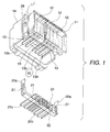
- Fig. 1 shows an insulator 11 used in switches for automobiles or the like.
- a predetermined conduction path (not shown in detail) is formed by burying conductors 12 so as to be coplanar with a surface of the insulator 11, the conductors 12 having been blanked from a metal plate.
- Each end of the conductors 12 being on an opposite side to the insulator 11, is bent as connecting terminals 13 horizontally arrangeed in a row.
- a connector-receiving main-part 14 is integrally molded with the connecting terminals 13 after inserting the connecting terminal thereinto.
- Fig. 2 shows a mold for molding the connector receiving main-part 14.
- the mold includes a lower mold 15, an upper mold 16, and an intermediate mold 17.
- the lower mold 15 has a projecting portion 15a and molds an inner lower half in a lower side and a depth side of the connector receiving main-part 14.
- the lower mold 15 is a fixed mold.
- the upper mold 16 has a projecting portion 16a and molds an inner upper half in an upper side and a depth side of the connector receiving main-part 14.
- the upper mold 16 is opened upward as indicated by an arrow A.
- the intermediate mold 17 molds the inner portion on the entrance of the connector receiving main-part 14.
- the intermediate mold 17 is designed to be slidable in such a horizontal direction as indicated by an arrow B (leftward as viewed in Fig. 2).
- These molds form a cavity 18 for molding the connector receiving main-part 14.
- the lower mold 15 may be movable and that the upper mold 16 may be fixed, or that both may be movable.
- the connector receiving main-part 14 is molded by injecting molten synthetic resin into the cavity 18 and solidifying the injected molten resin.
- the connector receiving main-part 14 has a squared tubelike shape surrounding the row of tips 13b of the connecting terminals 13.
- mold extracting holes 19, 20 are respectively formed in a lower side wall and an upper side wall extracted into the connector receiving main-part 14 by the projected portion 15a of the lower mold 15 and the projected portion 16a of the upper mold 16.
- Connecting terminals 21 are also formed by punching and bending a metal plate.
- a connector receiving auxiliary-part 22 which is separated from the connector receiving main-part 14, is molded with the connector receiving terminals 21 after inserting the connecting terminals 21 in the connector receiving auxiliary-part 22 so horizontally as to arrange in a row.
- Fig. 3 shows a mold for molding the connector receiving auxiliary-part 22.
- the mold includes a lower mold 23 and an upper mold 24.
- the lower mold 23 molds the bottom portion of the connector receiving auxiliary-part 22 and is a fixed mold.
- the upper mold 24 molds the top portion of the connector receiving auxiliary-part 22 and is designed to be opened upward as indicated by an arrow C.
- the lower mold and the upper mold form a cavity 25 for molding the connector receiving auxiliary-part 22.
- the lower mold 23 may be movable and that the upper mold 24 may be fixed, or that both may be movable.
- Base portion 21a of the connecting terminals 21 are positioned within the cavity 25, the connecting terminals 21 are positioned and fixed on the lower mold 23.
- the connector receiving auxiliary-part 22 is molded by injecting molten synthetic resin into the cavity 25 and solidifying the injected molten resin. In this case, the following steps may be taken.
- the entire part of a plurality of sets of the connector receiving auxiliary-parts concatenated through a frame 26 shown in Fig. 4 is subjected to transfer molding or the like, and the individual connector receiving auxiliary-parts are thereafter bent and punched.
- the molded connector receiving auxiliary-part 22 is beltlike with the row of tips 21b of the connecting terminals 21 not being enclosed.
- the connector receiving auxiliary-part 22 has rising portions 22a on both ends thereof, and the rising portions 22a have the mounting holes 27, respectively.
- the connector receiving main-part 14 has claws 28 on both outer lateral surfaces thereof (only one claw is shown in Fig. 1).
- the connector receiving auxiliary-part 22 having the connecting terminals 21 is mounted from the mold extracting hole 19 into the connector receiving main-part 14 to engage the claws 28 with the mounting holes 27, so that the connector receiving auxiliary-part 22 is coupled to the connector receiving main-part 14 to have the connecting terminals 13 placed above the connecting terminals 21.
- the inside of the connector receiving main-part 14 is molded not only by the intermediate mold 17 slided therein, but also the projected portions 15a, 16a of the lower and the upper molds 15, 16 that are the molds to be extracted through the mold extracting holes 19, 20.
- the sliding distance of the intermediate mold 17 can be reduced as much as the projected portions 15a, 16a of the lower and upper molds 15, 16 to be extracted through the mold extracting holes 19, 20.
- the mold structure can be accordingly simplified, which in turn contributes to cost reduction.
- the intermediate mold 17 which its sliding distance can be reduced, and the intermediate mold 17 is no necessity to touch the connecting terminals 13. Therefore, it is no necessity to form the slender holes into which the connecting terminals 13 are fitted, thereby it can be removed the cumbersome operation of fitting the connecting terminals into the slender holes. As a result, positioning adjustment and the like of the connecting terminals 13 to fit them into the slender holes can likewise be removed, which hence contributes to improving productivity.
- the connector receiving auxiliary-part 22 that is molded with a row of the connecting terminals 21 after inserting the connecting terminals 21 therein, there is no such restriction as placing the connecting terminals 21 under the connecting terminals 13, thereby allowing independent and free molding. Hence, further improved productivity can be provided.
- FIG. 6 shows a second embodiment of the invention.
- This embodiment is characterized as: not only forming mounting holes 30 into both end portions of a connector receiving auxiliary-part 29 which replaces the above-mentioned connector receiving auxiliary-part 22 but also forming pinlike projections 31 downward on both edges of bottom surface of the connector receiving main-part 14 to thereby fitting the projections 31 into the mounting holes 30; and welding the projecting tip portions of the projections 31 by heating to thereby couple the connector receiving auxiliary-part 29 to the connector receiving main-part 14.
- This embodiment can also provide the advantage similar to that provided by the aforementioned embodiment. It may also be proposed that a mounting structure in which the projections 31 are fitted into the mounting holes 30 be supplemented by the aforementioned mounting structure in which claws 28 are engaged with the mounting holes 27.
- the number of rows may be increased to three, four, and so on by molding the connector receiving auxiliary-part while inserting the connecting terminals on a single row basis and coupling the thus molded connector receiving auxiliary-part to the connector receiving main-part.
- the connector has a plurality of rows of connecting terminals arranged so as to be placed one upon another, and includes: a connector receiving main-part that is molded with a row of connecting terminals after inserting the connecting terminals therein, has mold extracting holes respectively formed in an upper side wall and a lower side wall of the connector receiving main-part surrounding tips of the row of the connecting terminals; and a connector receiving auxiliary-part that is molded with a row of the connecting terminals after inserting the connecting terminals therein so that tips of the connecting terminals are not molded.
- the connector receiving auxiliary-part having the connecting terminals that is mounted from one of the mold extracting holes into the connector receiving main-part.
Landscapes
- Engineering & Computer Science (AREA)
- Manufacturing & Machinery (AREA)
- Manufacturing Of Electrical Connectors (AREA)
- Injection Moulding Of Plastics Or The Like (AREA)
- Connections Arranged To Contact A Plurality Of Conductors (AREA)
- Connector Housings Or Holding Contact Members (AREA)
- Moulds For Moulding Plastics Or The Like (AREA)
Claims (7)
- Connecteur électrique moulé comprenant :caractérisé en ce que le connecteur comporte en outre :un boítier, etune chambre (14) de logement de connecteur formée sur le boítier, la chambre (14) de logement de connecteur ayant une rangée de bornes (13),des trous (19/20) d'extraction de moule destinés à l'extraction de moules (15/16) qui moulent l'intérieur de la chambre (14) de logement de connecteur, les trous (19/20) d'extraction de moule étant formés à une paroi latérale supérieure et une paroi latérale inférieure de la chambre (14) de logement de connecteur respectivement,une partie auxiliaire (22) formée séparément du boítier, la partie auxiliaire ayant une rangée de bornes (21), etun dispositif de montage destiné à retenir la partie auxiliaire (22) dans la chambre (14) de logement de connecteur afin que les rangées de bornes (13, 21) soient disposées d'une manière telle qu'elles sont les unes au-dessus des autres.
- Connecteur selon la revendication 1, dans lequel la chambre (14) de logement de connecteur et la rangée de bornes (13) sont formées par un corps moulé en une seule pièce.
- Connecteur selon la revendication 1 ou 2, dans lequel la partie auxiliaire (22) et la rangée de bornes (21) sont formées par un corps moulé en une seule pièce.
- Connecteur selon l'une des revendications 1 à 3, dans lequel le dispositif de montage comporte des griffes (28) formées sur les côtés opposés de la chambre (14) de logement de connecteur et des trous de montage (27) formés dans la partie auxiliaire (22) afin qu'ils coopèrent avec les griffes (28).
- Connecteur selon l'une des revendications 1 à 3, dans lequel le dispositif de montage comprend des saillies (34) qui dépassent sous la chambre (14) de logement de connecteur, et des trous de montage (30) formant deux extrémités de la partie auxiliaire (22) afin qu'ils coopèrent avec les griffes.
- Ensemble à moule de production de connecteur destiné à produire un connecteur, le connecteur comprenant un boítier et une chambre (14) de logement de connecteur formée sur le boítier et ayant une rangée de bornes (13), des trous (19, 20) d'extraction de moule étant formés à une paroi latérale supérieure et une paroi latérale inférieure de la chambre (14) de réception de connecteur respectivement, une partie auxiliaire (22) formée séparément du boítier et ayant une rangée de bornes (21), un dispositif de montage qui retient la partie auxiliaire (22) dans la chambre (14) de logement de connecteur, les rangées de bornes étant disposées les unes au-dessus des autres, l'ensemble à moule comprenant un premier moule inférieur (15) destiné à mouler une moitié inférieure de la chambre (14) de logement de connecteur, un premier moule supérieur (16) destiné à mouler une moitié supérieure de la chambre (14) de logement de connecteur, un moule intermédiaire (17) destiné à mouler une partie d'entrée de la chambre (14) de logement de connecteur, et une première cavité (18) délimitée par montage du premier moule inférieur (15), du premier moule supérieur (16) et du moule intermédiaire (17), un second moule inférieur (23) destiné au moulage d'une partie inférieure de la partie auxiliaire (22) placée sous une rangée de bornes (21), un second moule supérieur (24) destiné au moulage d'une partie supérieure de la partie auxiliaire (22) placée au-dessus de la partie inférieure, et une seconde cavité (25) délimitée par assemblage du second moule inférieur (23) et du second moule supérieur (24), la rangée de bornes (21) étant placée et fixée dans la seconde cavité (25), la résine synthétique moulée étant injectée dans la première et la seconde cavité (18, 25).
- Ensemble à moule de production de connecteur selon la revendication 6, dans lequel le premier moule inférieur (15) et/ou le premier moule supérieur (16) ont une partie en saillie (15a, 16a) respectivement pour la formation de l'intérieur de la chambre (14) de logement de connecteur.
Applications Claiming Priority (2)
| Application Number | Priority Date | Filing Date | Title |
|---|---|---|---|
| JP218455/94 | 1994-09-13 | ||
| JP06218455A JP3078709B2 (ja) | 1994-09-13 | 1994-09-13 | コネクタ接続装置 |
Publications (3)
| Publication Number | Publication Date |
|---|---|
| EP0702434A2 EP0702434A2 (fr) | 1996-03-20 |
| EP0702434A3 EP0702434A3 (fr) | 1996-07-10 |
| EP0702434B1 true EP0702434B1 (fr) | 1998-05-27 |
Family
ID=16720181
Family Applications (1)
| Application Number | Title | Priority Date | Filing Date |
|---|---|---|---|
| EP95114126A Expired - Lifetime EP0702434B1 (fr) | 1994-09-13 | 1995-09-08 | Connecteur électrique moulé |
Country Status (5)
| Country | Link |
|---|---|
| US (1) | US5653611A (fr) |
| EP (1) | EP0702434B1 (fr) |
| JP (1) | JP3078709B2 (fr) |
| CA (1) | CA2157694C (fr) |
| DE (1) | DE69502674T2 (fr) |
Families Citing this family (3)
| Publication number | Priority date | Publication date | Assignee | Title |
|---|---|---|---|---|
| US6796852B2 (en) * | 2001-07-23 | 2004-09-28 | Sumitomo Wiring Systems, Ltd. | Connector and method for producing the same |
| EP2955790B1 (fr) * | 2013-02-06 | 2020-02-26 | NSK Ltd. | Connecteur multi-pôle |
| CN111761778A (zh) * | 2019-04-01 | 2020-10-13 | 杭州三花研究院有限公司 | 一种电子膨胀阀的制造方法 |
Family Cites Families (4)
| Publication number | Priority date | Publication date | Assignee | Title |
|---|---|---|---|---|
| FR1247436A (fr) * | 1959-10-21 | 1960-12-02 | Cie Generale Entpr Elec | Connecteur pour raccordement électrique d'appareils amovibles |
| US5009614A (en) * | 1990-05-31 | 1991-04-23 | Amp Incorporated | Shielded cable assembly with floating ground |
| JPH04181676A (ja) * | 1990-11-15 | 1992-06-29 | Hirose Electric Co Ltd | 電気コネクタとその製作方法 |
| JP2712880B2 (ja) * | 1991-06-19 | 1998-02-16 | 住友電装株式会社 | 電線インサートコネクタの成形方法 |
-
1994
- 1994-09-13 JP JP06218455A patent/JP3078709B2/ja not_active Expired - Fee Related
-
1995
- 1995-09-07 CA CA002157694A patent/CA2157694C/fr not_active Expired - Fee Related
- 1995-09-08 DE DE69502674T patent/DE69502674T2/de not_active Expired - Lifetime
- 1995-09-08 EP EP95114126A patent/EP0702434B1/fr not_active Expired - Lifetime
- 1995-09-12 US US08/527,010 patent/US5653611A/en not_active Expired - Lifetime
Also Published As
| Publication number | Publication date |
|---|---|
| JPH0883635A (ja) | 1996-03-26 |
| US5653611A (en) | 1997-08-05 |
| DE69502674T2 (de) | 1998-12-10 |
| EP0702434A2 (fr) | 1996-03-20 |
| DE69502674D1 (de) | 1998-07-02 |
| JP3078709B2 (ja) | 2000-08-21 |
| EP0702434A3 (fr) | 1996-07-10 |
| CA2157694C (fr) | 2000-02-01 |
| CA2157694A1 (fr) | 1996-03-14 |
Similar Documents
| Publication | Publication Date | Title |
|---|---|---|
| US4269467A (en) | Electrical connector receptacle having molded conductors | |
| EP0817324B1 (fr) | Connecteur électrique pour l'utilisation dans ensembles miniaturisés de densité élevée et de nombre de contacts élevée et méthode de fabrication | |
| US4255009A (en) | Two row electrical connector | |
| CN1075262C (zh) | 插合模铸的电连接器及其制造方法 | |
| CA1283181C (fr) | Connecteur lateral de carte moule integre et contacts connexes et machineet methode de fabrication de ce connecteur | |
| EP0853356B1 (fr) | Procédé de fabrication d'un raccord et un raccord produit par moulage à insertion et son utilisation | |
| US6386917B1 (en) | Wire module and method of producing same | |
| US6217393B1 (en) | Appliance connector and production method thereof | |
| JP3676193B2 (ja) | 電気コネクタ及びその製造方法 | |
| EP3761462B1 (fr) | Procédé de fabrication de connecteur électrique et connecteur électrique | |
| US6368158B1 (en) | Electric connector having integrally molded terminals and guide pins | |
| US6370771B1 (en) | Method for making an electrical connector | |
| US6096257A (en) | Method for injection molding a connector | |
| JP2942691B2 (ja) | コネクタ差込部付きインシュレータの製造方法 | |
| CA2157694C (fr) | Dispositif de raccordement d'un connecteur | |
| FI67458B (fi) | Elektriskt kontaktdon med stickkontakt och stickdosa och foerfarande foer dess framstaellning | |
| US6416363B1 (en) | Electrical connector and method of making same | |
| US6293826B1 (en) | Electrical connector with metal side members and method of producing same | |
| EP1081811B1 (fr) | Procédé pour la fabrication de connecteurs électriques pour l'augmentation de leur coplanarité | |
| JP2000331750A (ja) | ジョイントコネクタ及びジョイントコネクタの製造方法 | |
| JPH08415B2 (ja) | メス側コネクターインサート成形法 | |
| JPH10189090A (ja) | 端子接続構造と電気接続箱及びその製造方法 | |
| JPS5823686B2 (ja) | 接点端子台 | |
| JPH0631094U (ja) | コネクタ | |
| JPH0829553B2 (ja) | コネクタのインサートモールド法及びその金型 |
Legal Events
| Date | Code | Title | Description |
|---|---|---|---|
| PUAI | Public reference made under article 153(3) epc to a published international application that has entered the european phase |
Free format text: ORIGINAL CODE: 0009012 |
|
| AK | Designated contracting states |
Kind code of ref document: A2 Designated state(s): DE FR GB |
|
| PUAL | Search report despatched |
Free format text: ORIGINAL CODE: 0009013 |
|
| AK | Designated contracting states |
Kind code of ref document: A3 Designated state(s): DE FR GB |
|
| RHK1 | Main classification (correction) |
Ipc: H01R 43/24 |
|
| 17P | Request for examination filed |
Effective date: 19961017 |
|
| 17Q | First examination report despatched |
Effective date: 19961121 |
|
| GRAG | Despatch of communication of intention to grant |
Free format text: ORIGINAL CODE: EPIDOS AGRA |
|
| RTI1 | Title (correction) | ||
| GRAG | Despatch of communication of intention to grant |
Free format text: ORIGINAL CODE: EPIDOS AGRA |
|
| GRAH | Despatch of communication of intention to grant a patent |
Free format text: ORIGINAL CODE: EPIDOS IGRA |
|
| GRAH | Despatch of communication of intention to grant a patent |
Free format text: ORIGINAL CODE: EPIDOS IGRA |
|
| GRAA | (expected) grant |
Free format text: ORIGINAL CODE: 0009210 |
|
| AK | Designated contracting states |
Kind code of ref document: B1 Designated state(s): DE FR GB |
|
| REF | Corresponds to: |
Ref document number: 69502674 Country of ref document: DE Date of ref document: 19980702 |
|
| ET | Fr: translation filed | ||
| PLBE | No opposition filed within time limit |
Free format text: ORIGINAL CODE: 0009261 |
|
| STAA | Information on the status of an ep patent application or granted ep patent |
Free format text: STATUS: NO OPPOSITION FILED WITHIN TIME LIMIT |
|
| 26N | No opposition filed | ||
| REG | Reference to a national code |
Ref country code: GB Ref legal event code: IF02 |
|
| PGFP | Annual fee paid to national office [announced via postgrant information from national office to epo] |
Ref country code: FR Payment date: 20110922 Year of fee payment: 17 Ref country code: DE Payment date: 20110831 Year of fee payment: 17 Ref country code: GB Payment date: 20110907 Year of fee payment: 17 |
|
| GBPC | Gb: european patent ceased through non-payment of renewal fee |
Effective date: 20120908 |
|
| REG | Reference to a national code |
Ref country code: FR Ref legal event code: ST Effective date: 20130531 |
|
| PG25 | Lapsed in a contracting state [announced via postgrant information from national office to epo] |
Ref country code: GB Free format text: LAPSE BECAUSE OF NON-PAYMENT OF DUE FEES Effective date: 20120908 Ref country code: DE Free format text: LAPSE BECAUSE OF NON-PAYMENT OF DUE FEES Effective date: 20130403 |
|
| PG25 | Lapsed in a contracting state [announced via postgrant information from national office to epo] |
Ref country code: FR Free format text: LAPSE BECAUSE OF NON-PAYMENT OF DUE FEES Effective date: 20121001 |
|
| REG | Reference to a national code |
Ref country code: DE Ref legal event code: R119 Ref document number: 69502674 Country of ref document: DE Effective date: 20130403 |