EP0702486A2 - Kompaktvideokamera, kombiniert mit VCR - Google Patents
Kompaktvideokamera, kombiniert mit VCR Download PDFInfo
- Publication number
- EP0702486A2 EP0702486A2 EP95118132A EP95118132A EP0702486A2 EP 0702486 A2 EP0702486 A2 EP 0702486A2 EP 95118132 A EP95118132 A EP 95118132A EP 95118132 A EP95118132 A EP 95118132A EP 0702486 A2 EP0702486 A2 EP 0702486A2
- Authority
- EP
- European Patent Office
- Prior art keywords
- viewfinder
- video camera
- median plane
- lid
- vcr
- Prior art date
- Legal status (The legal status is an assumption and is not a legal conclusion. Google has not performed a legal analysis and makes no representation as to the accuracy of the status listed.)
- Granted
Links
Images


Classifications
-
- G—PHYSICS
- G11—INFORMATION STORAGE
- G11B—INFORMATION STORAGE BASED ON RELATIVE MOVEMENT BETWEEN RECORD CARRIER AND TRANSDUCER
- G11B31/00—Arrangements for the associated working of recording or reproducing apparatus with related apparatus
- G11B31/006—Arrangements for the associated working of recording or reproducing apparatus with related apparatus with video camera or receiver
-
- H—ELECTRICITY
- H04—ELECTRIC COMMUNICATION TECHNIQUE
- H04N—PICTORIAL COMMUNICATION, e.g. TELEVISION
- H04N5/00—Details of television systems
- H04N5/76—Television signal recording
- H04N5/765—Interface circuits between an apparatus for recording and another apparatus
- H04N5/77—Interface circuits between an apparatus for recording and another apparatus between a recording apparatus and a television camera
- H04N5/772—Interface circuits between an apparatus for recording and another apparatus between a recording apparatus and a television camera the recording apparatus and the television camera being placed in the same enclosure
-
- H—ELECTRICITY
- H04—ELECTRIC COMMUNICATION TECHNIQUE
- H04N—PICTORIAL COMMUNICATION, e.g. TELEVISION
- H04N23/00—Cameras or camera modules comprising electronic image sensors; Control thereof
- H04N23/50—Constructional details
- H04N23/53—Constructional details of electronic viewfinders, e.g. rotatable or detachable
- H04N23/531—Constructional details of electronic viewfinders, e.g. rotatable or detachable being rotatable or detachable
-
- H—ELECTRICITY
- H04—ELECTRIC COMMUNICATION TECHNIQUE
- H04N—PICTORIAL COMMUNICATION, e.g. TELEVISION
- H04N5/00—Details of television systems
- H04N5/76—Television signal recording
- H04N5/78—Television signal recording using magnetic recording
- H04N5/782—Television signal recording using magnetic recording on tape
-
- Y—GENERAL TAGGING OF NEW TECHNOLOGICAL DEVELOPMENTS; GENERAL TAGGING OF CROSS-SECTIONAL TECHNOLOGIES SPANNING OVER SEVERAL SECTIONS OF THE IPC; TECHNICAL SUBJECTS COVERED BY FORMER USPC CROSS-REFERENCE ART COLLECTIONS [XRACs] AND DIGESTS
- Y10—TECHNICAL SUBJECTS COVERED BY FORMER USPC
- Y10S—TECHNICAL SUBJECTS COVERED BY FORMER USPC CROSS-REFERENCE ART COLLECTIONS [XRACs] AND DIGESTS
- Y10S358/00—Facsimile and static presentation processing
- Y10S358/906—Hand-held camera with recorder in a single unit
Definitions
- This invention relates generally to a unified video camera and video cassette recording and/or reproducing apparatus (VCR), and more particularly is directed to the provision of such unified video camera and VCR which is compact and light in weight so as to be conveniently portable.
- VCR video cassette recording and/or reproducing apparatus
- CTR cathode-ray tube
- An electronic viewfinder of the type using a CRT screen usually requires a relatively large space therefor, with the result that the viewfinder tends to project beyond the housing or body of the unified video camera and VCR and thereby resists reduction of the overall size of the device.
- a unified compact video camera and video cassette recording and/or reproducing apparatus comprising: a hollow body defining an interior space; a video camera unit including a camera lens assembly disposed in said interior space; a video cassette recording and/or reproducing unit disposed in said interior space, said video cassette recording and/or reproducing unit including a cassette holder compartment moveable between a loaded position wholly within said body and an eject position in which said holder compartment projects out of said opening; and a viewfinder characterised by: said interior space having a longitudinally extending vertical median plane and an opening along the top and a side of said body to one side of said plane; said video camera unit being offset toward the other side of median plane; said video cassette recording and/or reproducing unit being offset toward said one side of said median plane in longitudinally overlapping relation to said video camera unit; and by said viewfinder being disposed at said other side of said median plane above said video camera unit, said viewfinder being variable in axial length, in a telescopic manner, between
- a unified video camera and VCR has a recess extending along an upper portion of the body at the same side of the median plane as the viewfinder, and the viewfinder is pivotally mounted on the body for pivoting between a first angular position or orientation in which the viewfinder is substantially nested in the recess and a second angular position in which the viewfinder extends obliquely out of the recess.
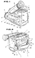
- a unified compact video camera and VCR 1 generally comprises a hollow body or housing 2 which is generally of rectangular box-shaped configuration and has a longitudinally extending median plane, for example, as indicated by the dot-dash line 2a on Fig. 3, a video camera unit 4 offset to one side of the median plane 2a within the housing 2, and a video cassette recording and/or reproducing (VCR) unit generally indicated at 3 and which is disposed in the hollow body 2 toward the other side of the median plane 2a in longitudinally overlapping relation to the video camera unit 4.
- VCR video cassette recording and/or reproducing
- the side of the body 2 which accommodates the video camera unit 4 is formed with a bulbous protrusion 4a extending along the lower portion of the body 2 and forming a receptacle for a camera lens assembly 6 which has a power zooming capability and is a component of the video camera unit 4.
- the camera lens assembly 6 has a lens cylinder 8 extending from the forward end or mouth of the receptacle 4a and carrying an objective lens 7 (Fig. 3).
- the VCR unit 3 includes a cassette compartment holder assembly 5 which, in its loading position and as shown on Fig. 2, defines an upper side wall portion 5a of the body 2 at the side of the latter remote from the bulbous protrusion 4a.
- the cassette compartment holder assembly 5 is adapted to receive a video cassette, for example, an 8-mm video tape cassette, and to eject the same through an opening extending along the top and a side of the body 2 at the same side of the longitudinal median plane as the VCR unit 3.
- a lid 12 is pivoted on the top of the body 2 for closing the top portion of the opening and thereby covering and protecting the cassette in the cassette compartment holder assembly 5 when the latter is disposed in a loading position, as hereinafter described in detail.
- a viewfinder assembly 9 is mounted on the body 2 at the same side as the video camera unit 4 but is disposed above the camera lens assembly 6 in the protrusion 4a.
- the viewfinder 9 is mounted on the body 2 for pivoting between a first orientation or position shown in full lines on Fig. 4 and in which the viewfinder 9 is accommodated substantially within a recess or depression 4b extending along the body 2 above the protrusion 4a, and an upwardly pivoted position, indicated in dot-dash lines at 9' on Fig. 4 and in which the viewfinder extends obliquely upward out of the recess 4b.
- the range of pivotal movement of the viewfinder 9 is desirably approximately 90°.
- the viewfinder 9 includes a viewing screen assembly 50 comprised of upper and lower, semi-cylindrical housing portions 50a and 50b which are suitably secured to each other and contain a cathode-ray tube (CRT) 51 having its screen exposed at a window 50d formed in an end wall 50c of the viewing screen assembly 50.
- CTR cathode-ray tube
- a transverse extension 52 (Figs. 3 and 4) which is rotably mounted within a receptacle 4c formed in the body 2 (Fig. 4) for permitting the described pivotal movement of the viewfinder 9 through approximately 90° upwardly from the nested position of the latter.
- the lower semi-cylindrical portion 50b of the housing of the viewing screen assembly 50 has a recess 50e (Fig. 4) therein for receiving a latching projection 4e projecting from the bottom surface of the recess 4b. Engagement of the latching projection 4e in the recess 50e is effective to prevent inadvertent movement of the viewfinder 9 from its reset position.
- An edit switch 53 which is to be operated in an edit mode of the apparatus also extends from the body 2 within the recess 4b so as to be hidden from view and protected by the viewfinder 9 when the latter is within its rest position shown in full lines on Fig. 4.
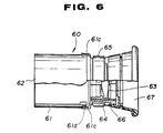
- the viewfinder 9 further comprises an eye piece assembly 60 which generally includes a cylindrical holder 61, an outer housing 62, a lens 63 within a lens holder 64, a lens adjustment ring 65 and an eye cap holder 66.
- the holder 61 is shown to include a relatively large diameter cylindrical section 61a and a smaller diameter cylindrical section 61e.
- the large diameter section 61a is dimensioned to be slidable on the housing of viewing screen assembly 50 and has 4 substantially L-shaped guide slots 61b formed therein at regular intervals around the cylindrical section 61a. These guide slots 61b slidably receive respective connecting pins 54 which project radially outward from the outer surface of the viewing screen assembly 50 for positioning the eye piece assembly 60 relative thereto.
- a pair of diametrically opposed strips 61c formed with inwardly projections 61d (Fig. 6) are offset radially outward from the large diameter section 61 adjacent the end of the latter to which the small diameter section 61e is connected.
- the engaging strips 61c are spaced radially outward from the outer surface of the large diameter section 61a so that the inwardly directed projections 61d on the strips 61c are engageable in cutouts 62a formed in an edge portion of the cylindrical cover 62 when the latter extends axially over the large diameter section 61a of the finder holder 61 (Fig. 6).
- the lens holder 64 carrying the lens 63 is diametrically dimensioned so as to be rotatable within the smaller diameter section 61e of the holder 61.
- the lens adjustment ring 65 is diametrically dimensioned so as to be rotatable around the outer surface of the section 61e, and the ring 65 is shown to be provided with a pair of inwardly projecting pins 65a extending radially therefrom.
- Such inwardly projecting pins 65a can extend through T-shaped slots 61f formed in the small diameter section 61e and each having a stem opening at the free edge of the section 61e.
- the inwardly projecting pins 65a are sufficiently long so that the inner ends thereof can slidably engage in respective helically arranged grooves 64a formed in the outer surface of the lens holder 64.
- the eye cap holder 66 is dimensioned to fit over the free end portion of the smaller diameter section 61e and has diametrically opposed openings 66a positioned to be engaged by claws 61g extending outwardly from the section 61e.
- the lens holder 64 is further formed, in its outer surface, with a pair of axially extending grooves 64b which receive axial guide projections 61h extending inwardly from the inner surface of the section 61e of the holder 61.
- the engagement of the projections 61h in the grooves 64b serves to rotably couple the lens holder 64 and the finder holder 61 while permitting relative axial displacements thereof.
- the focal distance of the lens 63 is selected so that the screen of the CRT 51 can be brought into focus when viewed through the eye piece assembly 60 only if the finder holder 61 is in an expanded condition in which it is shifted away from the viewing screen assembly 50.
- the lens 63 is maintained out of focus in respect to the screen of the CRT 51.
- the described viewfinder 9 embodying this invention is constructed to be maintained in its contracted condition by restricting movement of each of the connecting pins 54 along the respective slot 61b in the axial expanding direction by means of a projection 61b' resiliently projecting into the foot or circumferencially extending end portion of each L-shaped slot 61b.
- the viewfinder 9 can be maintained in its expanded condition by restricting the movement of each of the connecting pins 54 along the respective slot 61b by means of a projection 61b extending resiliently into each L-shaped slot 61b near to the end of the axially directed portion thereof.
- the viewfinder 9 With the arrangement of the viewfinder 9 as described above, the latter can be stored, when not in use, in its contracted condition so as to be wholly contained within the recess 4b of the body 2, whereby to minimize the overall dimensions of the unified video camera and VCR 1. In such stored position, the lens 63 is not focused in respect to the screen of the CTR 51.
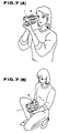
- the viewfinder 9 when operating the unified video camera and VCR 1, the viewfinder 9 is manipulated to its expanded condition so that an eye cap 67 (Fig. 6) mounted on the eye cap holder 66 extends well beyond the camera body 2 for easy access by the operator's eye.
- the pivotal position of the viewfinder 9 can be selected for convenient use thereof when operating the unified video camera and VCR from an erect position (Fig. 7A) or from a low or crouching position (Fig. 7B).
- circuit boards generally indicated at 200 are preferably separated into a group of circuit boards 202 for the video camera functions, and a group of circuit boards 204 for the VCR functions.
- Such arrangement or layout of the circuit boards in two groups 202 and 204 makes it possible to reduce the number of circuit elements and thereby assist in minimizing the size of the unified video camera and VCR.
Landscapes
- Engineering & Computer Science (AREA)
- Multimedia (AREA)
- Signal Processing (AREA)
- Studio Devices (AREA)
- Accessories Of Cameras (AREA)
- Packaging Of Annular Or Rod-Shaped Articles, Wearing Apparel, Cassettes, Or The Like (AREA)
- Exposure Control For Cameras (AREA)
- Color Television Image Signal Generators (AREA)
- Viewfinders (AREA)
- Camera Bodies And Camera Details Or Accessories (AREA)
- Details Of Cameras Including Film Mechanisms (AREA)
- Casings For Electric Apparatus (AREA)
Applications Claiming Priority (13)
| Application Number | Priority Date | Filing Date | Title |
|---|---|---|---|
| JP13635789 | 1989-05-30 | ||
| JP136355/89 | 1989-05-30 | ||
| JP13635689 | 1989-05-30 | ||
| JP1136358A JP2840759B2 (ja) | 1989-05-30 | 1989-05-30 | カメラ一体型記録装置 |
| JP136357/89 | 1989-05-30 | ||
| JP1136355A JP2893718B2 (ja) | 1989-05-30 | 1989-05-30 | カメラ一体型記録装置 |
| JP13635589 | 1989-05-30 | ||
| JP136358/89 | 1989-05-30 | ||
| JP136356/89 | 1989-05-30 | ||
| JP13635889 | 1989-05-30 | ||
| JP1136356A JP2840758B2 (ja) | 1989-05-30 | 1989-05-30 | カメラ一体型記録装置 |
| JP1136357A JP2855658B2 (ja) | 1989-05-30 | 1989-05-30 | 撮像装置 |
| EP90305791A EP0400944B1 (de) | 1989-05-30 | 1990-05-29 | Kompakt-Videokamera und VCR kombiniert |
Related Parent Applications (2)
| Application Number | Title | Priority Date | Filing Date |
|---|---|---|---|
| EP90305791A Division EP0400944B1 (de) | 1989-05-30 | 1990-05-29 | Kompakt-Videokamera und VCR kombiniert |
| EP90305791.7 Division | 1990-05-29 |
Publications (3)
| Publication Number | Publication Date |
|---|---|
| EP0702486A2 true EP0702486A2 (de) | 1996-03-20 |
| EP0702486A3 EP0702486A3 (de) | 1997-10-01 |
| EP0702486B1 EP0702486B1 (de) | 2000-08-16 |
Family
ID=27471991
Family Applications (2)
| Application Number | Title | Priority Date | Filing Date |
|---|---|---|---|
| EP90305791A Expired - Lifetime EP0400944B1 (de) | 1989-05-30 | 1990-05-29 | Kompakt-Videokamera und VCR kombiniert |
| EP95118132A Expired - Lifetime EP0702486B1 (de) | 1989-05-30 | 1990-05-29 | Kompaktvideokamera, kombiniert mit VCR |
Family Applications Before (1)
| Application Number | Title | Priority Date | Filing Date |
|---|---|---|---|
| EP90305791A Expired - Lifetime EP0400944B1 (de) | 1989-05-30 | 1990-05-29 | Kompakt-Videokamera und VCR kombiniert |
Country Status (21)
| Country | Link |
|---|---|
| US (1) | US5469271A (de) |
| EP (2) | EP0400944B1 (de) |
| KR (1) | KR0185392B1 (de) |
| AR (1) | AR243310A1 (de) |
| AT (2) | ATE140354T1 (de) |
| AU (1) | AU638457B2 (de) |
| BR (1) | BR9002564A (de) |
| DE (2) | DE69027716T2 (de) |
| DK (2) | DK0702486T3 (de) |
| ES (2) | ES2088968T3 (de) |
| FI (1) | FI98331C (de) |
| IE (1) | IE75732B1 (de) |
| IL (1) | IL94538A (de) |
| MX (1) | MX173746B (de) |
| NO (1) | NO179850C (de) |
| NZ (1) | NZ233779A (de) |
| PH (1) | PH30510A (de) |
| PL (1) | PL163815B1 (de) |
| PT (1) | PT94183B (de) |
| RU (1) | RU1838834C (de) |
| TR (1) | TR25434A (de) |
Families Citing this family (28)
| Publication number | Priority date | Publication date | Assignee | Title |
|---|---|---|---|---|
| JPH03280787A (ja) * | 1990-03-29 | 1991-12-11 | Sony Corp | ビデオカメラ |
| JPH04144368A (ja) * | 1990-10-04 | 1992-05-18 | Fuji Photo Film Co Ltd | カメラ |
| US5493409A (en) * | 1990-11-29 | 1996-02-20 | Minolta Camera Kabushiki Kaisha | Still video camera having a printer capable of printing a photographed image in a plurality of printing modes |
| DE69229895T2 (de) * | 1991-06-18 | 2000-04-20 | Canon K.K. | Videokamera |
| DE69225097T2 (de) * | 1991-06-18 | 1998-10-15 | Canon Kk | Kamera mit integriertem Video-Aufnahmegerät |
| JP3039709B2 (ja) * | 1991-07-24 | 2000-05-08 | キヤノン株式会社 | ビデオカメラ |
| US5828921A (en) * | 1993-12-28 | 1998-10-27 | Canon Kabushiki Kaisha | Camera or apparatus adapted to use film cartridge or device applicable to such camera or apparatus |
| USD380764S (en) * | 1995-03-16 | 1997-07-08 | Sony Corporation | Combined video tape recorder and camera |
| KR0127341Y1 (ko) * | 1995-05-04 | 1998-12-15 | 구자홍 | 캠코더용 액정모니터부의 빛가리개 |
| JP3612801B2 (ja) * | 1995-07-03 | 2005-01-19 | ソニー株式会社 | 電子機器 |
| JP2955510B2 (ja) * | 1996-04-12 | 1999-10-04 | 池上通信機株式会社 | 撮像装置のエジェクト装置 |
| DE19839218C2 (de) * | 1997-08-29 | 2000-02-24 | Fuji Photo Optical Co Ltd | Froschperspektiven-Griffvorrichtung für eine elektronische Nachrichten-Aufnahme-Kamera |
| US8240077B2 (en) | 2002-03-04 | 2012-08-14 | Larry Holmberg | Range finder for weapons |
| US6556245B1 (en) | 1999-03-08 | 2003-04-29 | Larry Allan Holmberg | Game hunting video camera |
| JP2002253328A (ja) * | 2001-03-01 | 2002-09-10 | Sharp Corp | ハンドストラップ取付部を有するカメラ付モバイル機器 |
| USD483782S1 (en) | 2002-03-01 | 2003-12-16 | Flir Systems Ab | Infrared camera |
| US20050147397A1 (en) | 2003-12-17 | 2005-07-07 | Sony Corporation | Image pickup apparatus |
| CN100342256C (zh) * | 2003-12-23 | 2007-10-10 | 明基电通股份有限公司 | 旋转机构 |
| KR20050087999A (ko) * | 2004-02-28 | 2005-09-01 | 삼성전자주식회사 | 뷰파인더 및 이를 구비한 영상촬영장치 |
| KR20050088002A (ko) * | 2004-02-28 | 2005-09-01 | 삼성전자주식회사 | 영상촬영장치 및 그 조립방법 |
| KR20050090821A (ko) * | 2004-03-10 | 2005-09-14 | 삼성전자주식회사 | 영상촬영장치의 하우징 커버 |
| US7171114B2 (en) * | 2004-07-12 | 2007-01-30 | Milton Curtis A | Mirror-mimicking video system |
| CN101346986A (zh) * | 2005-12-26 | 2009-01-14 | 松下电器产业株式会社 | 摄像装置 |
| US20100186234A1 (en) | 2009-01-28 | 2010-07-29 | Yehuda Binder | Electric shaver with imaging capability |
| JP2011142369A (ja) * | 2009-12-07 | 2011-07-21 | Sanyo Electric Co Ltd | 録画機能を具えた携帯型電子機器 |
| US8656625B2 (en) | 2010-12-29 | 2014-02-25 | Larry Holmberg | Accessory mount |
| US8656624B2 (en) | 2010-12-29 | 2014-02-25 | Larry Holmberg | Universal device mount |
| US9004784B2 (en) * | 2013-03-14 | 2015-04-14 | Rolf Kestermann | Camera mount assembly, methods of production and uses thereof |
Family Cites Families (7)
| Publication number | Priority date | Publication date | Assignee | Title |
|---|---|---|---|---|
| JPS57212872A (en) * | 1981-06-24 | 1982-12-27 | Canon Inc | Magnetic recorder and reproducer |
| JPS6019269U (ja) * | 1983-07-15 | 1985-02-09 | オリンパス光学工業株式会社 | ビデオカメラ |
| JPS60132472A (ja) * | 1983-12-21 | 1985-07-15 | Sony Corp | 撮影装置 |
| KR910001707Y1 (ko) * | 1986-06-05 | 1991-03-18 | 니뽕 빅터 가부시끼가이샤 | 카메라 일체형 비디오 테이프 레코더 |
| JPS63193773A (ja) * | 1987-02-06 | 1988-08-11 | Hitachi Ltd | 再生機能を具備したvtr一体形カメラ |
| JPH0831977B2 (ja) * | 1987-08-21 | 1996-03-27 | ソニー株式会社 | ビデオカメラ |
| EP0318015B1 (de) * | 1987-11-25 | 1995-02-01 | Fuji Photo Film Co., Ltd. | Videokamera |
-
1990
- 1990-05-23 AU AU55891/90A patent/AU638457B2/en not_active Expired
- 1990-05-23 NZ NZ233779A patent/NZ233779A/xx unknown
- 1990-05-28 IL IL9453890A patent/IL94538A/en unknown
- 1990-05-29 DK DK95118132T patent/DK0702486T3/da active
- 1990-05-29 KR KR1019900007753A patent/KR0185392B1/ko not_active Expired - Fee Related
- 1990-05-29 DE DE69027716T patent/DE69027716T2/de not_active Expired - Fee Related
- 1990-05-29 RU SU904830106A patent/RU1838834C/ru active
- 1990-05-29 AT AT90305791T patent/ATE140354T1/de not_active IP Right Cessation
- 1990-05-29 AT AT95118132T patent/ATE195622T1/de not_active IP Right Cessation
- 1990-05-29 DK DK90305791.7T patent/DK0400944T3/da active
- 1990-05-29 ES ES90305791T patent/ES2088968T3/es not_active Expired - Lifetime
- 1990-05-29 NO NO902359A patent/NO179850C/no not_active IP Right Cessation
- 1990-05-29 FI FI902671A patent/FI98331C/fi active IP Right Grant
- 1990-05-29 EP EP90305791A patent/EP0400944B1/de not_active Expired - Lifetime
- 1990-05-29 DE DE69033609T patent/DE69033609T2/de not_active Expired - Fee Related
- 1990-05-29 EP EP95118132A patent/EP0702486B1/de not_active Expired - Lifetime
- 1990-05-29 IE IE193090A patent/IE75732B1/en not_active IP Right Cessation
- 1990-05-29 MX MX020920A patent/MX173746B/es unknown
- 1990-05-29 ES ES95118132T patent/ES2148408T3/es not_active Expired - Lifetime
- 1990-05-29 PT PT94183A patent/PT94183B/pt not_active IP Right Cessation
- 1990-05-30 PL PL90285403A patent/PL163815B1/pl unknown
- 1990-05-30 BR BR909002564A patent/BR9002564A/pt not_active IP Right Cessation
- 1990-05-30 PH PH40587A patent/PH30510A/en unknown
- 1990-05-30 AR AR90316981A patent/AR243310A1/es active
- 1990-05-30 TR TR90/0512A patent/TR25434A/xx unknown
-
1994
- 1994-04-01 US US08/222,314 patent/US5469271A/en not_active Expired - Lifetime
Also Published As
Similar Documents
| Publication | Publication Date | Title |
|---|---|---|
| EP0702486B1 (de) | Kompaktvideokamera, kombiniert mit VCR | |
| US5303062A (en) | Folding camcorder for compact storage | |
| JPH0922685A (ja) | 電子機器 | |
| KR200159074Y1 (ko) | 렌즈 캡 | |
| US7771866B2 (en) | Battery-locking mechanism for electronic apparatus | |
| JP2748653B2 (ja) | カメラ一体型vtr | |
| JPH0922585A (ja) | 電子機器 | |
| CA2017700C (en) | Unified compact video camera and vcr | |
| JPH031768A (ja) | カメラ一体型記録装置 | |
| JP2855658B2 (ja) | 撮像装置 | |
| JP3024166B2 (ja) | 撮像装置 | |
| JPH0918159A (ja) | 電子機器 | |
| JP2893718B2 (ja) | カメラ一体型記録装置 | |
| KR20010030564A (ko) | 전자 카메라 장치 | |
| JPH0698216A (ja) | カメラのレンズカバー開閉機構 | |
| JPS6062277A (ja) | ビデオカメラ装置 | |
| JPH046013Y2 (de) | ||
| KR940011884B1 (ko) | 카메라 일체형 브이씨알 | |
| US5950032A (en) | Camera | |
| JPH06132712A (ja) | アンテナの引き出し機構を備えた携帯用電話機 | |
| JPH03198480A (ja) | マイク内蔵型ビデオカメラ | |
| JPH0943673A (ja) | カメラ用外部電源装置及びこれを使用するカメラ | |
| JP2000078441A (ja) | 携帯型ビデオカメラ | |
| JPH08279941A (ja) | ビデオカメラ | |
| JPH04108275A (ja) | Vtr一体形カメラ |
Legal Events
| Date | Code | Title | Description |
|---|---|---|---|
| PUAI | Public reference made under article 153(3) epc to a published international application that has entered the european phase |
Free format text: ORIGINAL CODE: 0009012 |
|
| AC | Divisional application: reference to earlier application |
Ref document number: 400944 Country of ref document: EP |
|
| AK | Designated contracting states |
Kind code of ref document: A2 Designated state(s): AT BE CH DE DK ES FR GB IT LI LU NL SE |
|
| PUAL | Search report despatched |
Free format text: ORIGINAL CODE: 0009013 |
|
| AK | Designated contracting states |
Kind code of ref document: A3 Designated state(s): AT BE CH DE DK ES FR GB IT LI LU NL SE |
|
| 17P | Request for examination filed |
Effective date: 19980304 |
|
| GRAG | Despatch of communication of intention to grant |
Free format text: ORIGINAL CODE: EPIDOS AGRA |
|
| 17Q | First examination report despatched |
Effective date: 19990819 |
|
| GRAG | Despatch of communication of intention to grant |
Free format text: ORIGINAL CODE: EPIDOS AGRA |
|
| GRAH | Despatch of communication of intention to grant a patent |
Free format text: ORIGINAL CODE: EPIDOS IGRA |
|
| GRAH | Despatch of communication of intention to grant a patent |
Free format text: ORIGINAL CODE: EPIDOS IGRA |
|
| GRAA | (expected) grant |
Free format text: ORIGINAL CODE: 0009210 |
|
| AC | Divisional application: reference to earlier application |
Ref document number: 400944 Country of ref document: EP |
|
| AK | Designated contracting states |
Kind code of ref document: B1 Designated state(s): AT BE CH DE DK ES FR GB IT LI LU NL SE |
|
| REF | Corresponds to: |
Ref document number: 195622 Country of ref document: AT Date of ref document: 20000915 Kind code of ref document: T |
|
| REG | Reference to a national code |
Ref country code: CH Ref legal event code: NV Representative=s name: ISLER & PEDRAZZINI AG Ref country code: CH Ref legal event code: EP |
|
| REG | Reference to a national code |
Ref country code: DK Ref legal event code: T3 |
|
| REF | Corresponds to: |
Ref document number: 69033609 Country of ref document: DE Date of ref document: 20000921 |
|
| ITF | It: translation for a ep patent filed | ||
| REG | Reference to a national code |
Ref country code: ES Ref legal event code: FG2A Ref document number: 2148408 Country of ref document: ES Kind code of ref document: T3 |
|
| ET | Fr: translation filed | ||
| PLBE | No opposition filed within time limit |
Free format text: ORIGINAL CODE: 0009261 |
|
| STAA | Information on the status of an ep patent application or granted ep patent |
Free format text: STATUS: NO OPPOSITION FILED WITHIN TIME LIMIT |
|
| 26N | No opposition filed | ||
| REG | Reference to a national code |
Ref country code: GB Ref legal event code: IF02 |
|
| REG | Reference to a national code |
Ref country code: CH Ref legal event code: PCAR Free format text: ISLER & PEDRAZZINI AG;POSTFACH 1772;8027 ZUERICH (CH) |
|
| PGFP | Annual fee paid to national office [announced via postgrant information from national office to epo] |
Ref country code: DK Payment date: 20080515 Year of fee payment: 19 Ref country code: DE Payment date: 20080605 Year of fee payment: 19 Ref country code: CH Payment date: 20080527 Year of fee payment: 19 |
|
| PGFP | Annual fee paid to national office [announced via postgrant information from national office to epo] |
Ref country code: AT Payment date: 20080514 Year of fee payment: 19 |
|
| PGFP | Annual fee paid to national office [announced via postgrant information from national office to epo] |
Ref country code: IT Payment date: 20080527 Year of fee payment: 19 |
|
| PGFP | Annual fee paid to national office [announced via postgrant information from national office to epo] |
Ref country code: GB Payment date: 20080604 Year of fee payment: 19 |
|
| PGFP | Annual fee paid to national office [announced via postgrant information from national office to epo] |
Ref country code: BE Payment date: 20081128 Year of fee payment: 19 |
|
| PGFP | Annual fee paid to national office [announced via postgrant information from national office to epo] |
Ref country code: NL Payment date: 20090504 Year of fee payment: 20 Ref country code: ES Payment date: 20090605 Year of fee payment: 20 |
|
| PGFP | Annual fee paid to national office [announced via postgrant information from national office to epo] |
Ref country code: SE Payment date: 20090512 Year of fee payment: 20 Ref country code: LU Payment date: 20090616 Year of fee payment: 20 |
|
| BERE | Be: lapsed |
Owner name: *SONY CORP. Effective date: 20090531 |
|
| REG | Reference to a national code |
Ref country code: CH Ref legal event code: PL |
|
| REG | Reference to a national code |
Ref country code: DK Ref legal event code: EBP |
|
| GBPC | Gb: european patent ceased through non-payment of renewal fee |
Effective date: 20090529 |
|
| PG25 | Lapsed in a contracting state [announced via postgrant information from national office to epo] |
Ref country code: LI Free format text: LAPSE BECAUSE OF NON-PAYMENT OF DUE FEES Effective date: 20090531 Ref country code: CH Free format text: LAPSE BECAUSE OF NON-PAYMENT OF DUE FEES Effective date: 20090531 Ref country code: AT Free format text: LAPSE BECAUSE OF NON-PAYMENT OF DUE FEES Effective date: 20090529 |
|
| REG | Reference to a national code |
Ref country code: FR Ref legal event code: ST Effective date: 20100129 |
|
| PG25 | Lapsed in a contracting state [announced via postgrant information from national office to epo] |
Ref country code: FR Free format text: LAPSE BECAUSE OF NON-PAYMENT OF DUE FEES Effective date: 20090602 Ref country code: DK Free format text: LAPSE BECAUSE OF NON-PAYMENT OF DUE FEES Effective date: 20090531 |
|
| PGFP | Annual fee paid to national office [announced via postgrant information from national office to epo] |
Ref country code: FR Payment date: 20080514 Year of fee payment: 19 |
|
| PG25 | Lapsed in a contracting state [announced via postgrant information from national office to epo] |
Ref country code: GB Free format text: LAPSE BECAUSE OF NON-PAYMENT OF DUE FEES Effective date: 20090529 |
|
| REG | Reference to a national code |
Ref country code: NL Ref legal event code: V4 Effective date: 20100529 |
|
| EUG | Se: european patent has lapsed | ||
| PG25 | Lapsed in a contracting state [announced via postgrant information from national office to epo] |
Ref country code: DE Free format text: LAPSE BECAUSE OF NON-PAYMENT OF DUE FEES Effective date: 20091201 Ref country code: BE Free format text: LAPSE BECAUSE OF NON-PAYMENT OF DUE FEES Effective date: 20090531 |
|
| REG | Reference to a national code |
Ref country code: ES Ref legal event code: FD2A Effective date: 20100531 |
|
| PG25 | Lapsed in a contracting state [announced via postgrant information from national office to epo] |
Ref country code: NL Free format text: LAPSE BECAUSE OF EXPIRATION OF PROTECTION Effective date: 20100529 |
|
| PG25 | Lapsed in a contracting state [announced via postgrant information from national office to epo] |
Ref country code: ES Free format text: LAPSE BECAUSE OF EXPIRATION OF PROTECTION Effective date: 20100531 |
|
| PG25 | Lapsed in a contracting state [announced via postgrant information from national office to epo] |
Ref country code: IT Free format text: LAPSE BECAUSE OF NON-PAYMENT OF DUE FEES Effective date: 20090529 |