EP0702613B1 - Verfahren und vorrichtung zum schleifen der walzen von walzenfuehrungen in walzwerken und walzenfuehrung, bei der das verfahren angewandt werden kann - Google Patents
Verfahren und vorrichtung zum schleifen der walzen von walzenfuehrungen in walzwerken und walzenfuehrung, bei der das verfahren angewandt werden kann Download PDFInfo
- Publication number
- EP0702613B1 EP0702613B1 EP94919048A EP94919048A EP0702613B1 EP 0702613 B1 EP0702613 B1 EP 0702613B1 EP 94919048 A EP94919048 A EP 94919048A EP 94919048 A EP94919048 A EP 94919048A EP 0702613 B1 EP0702613 B1 EP 0702613B1
- Authority
- EP
- European Patent Office
- Prior art keywords
- roller
- bearing
- guide
- grinding
- roller guide
- Prior art date
- Legal status (The legal status is an assumption and is not a legal conclusion. Google has not performed a legal analysis and makes no representation as to the accuracy of the status listed.)
- Expired - Lifetime
Links
- 238000005096 rolling process Methods 0.000 title claims abstract description 22
- 238000000034 method Methods 0.000 title claims abstract description 18
- 230000002093 peripheral effect Effects 0.000 claims abstract description 6
- 230000000295 complement effect Effects 0.000 claims 1
- 230000000717 retained effect Effects 0.000 abstract 1
- 239000002184 metal Substances 0.000 description 5
- 238000004519 manufacturing process Methods 0.000 description 2
- 239000000463 material Substances 0.000 description 2
- 238000010276 construction Methods 0.000 description 1
- 239000000356 contaminant Substances 0.000 description 1
- 239000002826 coolant Substances 0.000 description 1
- 239000000428 dust Substances 0.000 description 1
- 230000000694 effects Effects 0.000 description 1
- 239000012634 fragment Substances 0.000 description 1
- 238000011065 in-situ storage Methods 0.000 description 1
- 239000000314 lubricant Substances 0.000 description 1
- 239000002245 particle Substances 0.000 description 1
Images

Classifications
-
- B—PERFORMING OPERATIONS; TRANSPORTING
- B24—GRINDING; POLISHING
- B24B—MACHINES, DEVICES, OR PROCESSES FOR GRINDING OR POLISHING; DRESSING OR CONDITIONING OF ABRADING SURFACES; FEEDING OF GRINDING, POLISHING, OR LAPPING AGENTS
- B24B19/00—Single-purpose machines or devices for particular grinding operations not covered by any other main group
- B24B19/02—Single-purpose machines or devices for particular grinding operations not covered by any other main group for grinding grooves, e.g. on shafts, in casings, in tubes, homokinetic joint elements
- B24B19/06—Single-purpose machines or devices for particular grinding operations not covered by any other main group for grinding grooves, e.g. on shafts, in casings, in tubes, homokinetic joint elements for grinding races, e.g. roller races
-
- B—PERFORMING OPERATIONS; TRANSPORTING
- B21—MECHANICAL METAL-WORKING WITHOUT ESSENTIALLY REMOVING MATERIAL; PUNCHING METAL
- B21B—ROLLING OF METAL
- B21B39/00—Arrangements for moving, supporting, or positioning work, or controlling its movement, combined with or arranged in, or specially adapted for use in connection with, metal-rolling mills
- B21B39/14—Guiding, positioning or aligning work
- B21B39/16—Guiding, positioning or aligning work immediately before entering or after leaving the pass
- B21B39/165—Guides or guide rollers for rods, bars, rounds, tubes ; Aligning guides
-
- B—PERFORMING OPERATIONS; TRANSPORTING
- B24—GRINDING; POLISHING
- B24B—MACHINES, DEVICES, OR PROCESSES FOR GRINDING OR POLISHING; DRESSING OR CONDITIONING OF ABRADING SURFACES; FEEDING OF GRINDING, POLISHING, OR LAPPING AGENTS
- B24B5/00—Machines or devices designed for grinding surfaces of revolution on work, including those which also grind adjacent plane surfaces; Accessories therefor
- B24B5/02—Machines or devices designed for grinding surfaces of revolution on work, including those which also grind adjacent plane surfaces; Accessories therefor involving centres or chucks for holding work
- B24B5/16—Machines or devices designed for grinding surfaces of revolution on work, including those which also grind adjacent plane surfaces; Accessories therefor involving centres or chucks for holding work for grinding peculiarly surfaces, e.g. bulged
-
- B—PERFORMING OPERATIONS; TRANSPORTING
- B21—MECHANICAL METAL-WORKING WITHOUT ESSENTIALLY REMOVING MATERIAL; PUNCHING METAL
- B21B—ROLLING OF METAL
- B21B28/00—Maintaining rolls or rolling equipment in effective condition
- B21B28/02—Maintaining rolls in effective condition, e.g. reconditioning
Definitions
- the present invention relates to a method and to a device for grinding the rollers of rolling mill roller-guides, and a roller guide which enables the method to be carried out.
- the object of the present invention is to increase the life span of roller guide bearings in rolling mills.
- this object is achieved with a method for grinding grooves in the rollers of roller guides in roller mill, wherein a unit which is readily attachable to and removable from the remainder of the guide and which comprises the roller of said roller guide together with its bearing, is placed in a carrier of a grinding device, and the roller of said guide is caused to rotate in its own bearing during a grinding process.
- the groove formed in the roller will always lie precisely at right angles to the rotational axis of the roller and the rolled metal will move precisely in the rolling line.
- the invention also relates to a device for carrying out the method, wherein said device includes a carrier for supporting a unit of a roller guide, which unit comprises the roller of the roller guide together with its bearing, so that the roller is able to rotate freely in its bearing, a grinding tool which can be moved radially in relation to a roller supported by the carrier, and means for rotating such a roller.
- the roller of said roller guide is constructed together with its bearing to form a unit said bearing comprising an attachment sleeve rotably supporting the roller, one end of said sleeve having means for readily removably attaching said unit to the remainder of the roller guide.
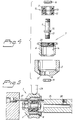
- Figures 1 to 4 illustrate a roller guide for rolling mills, said guide being constructed to permit the inventive grinding method to be applied.
- the roller guide includes conventionally two grooved and rotatable rollers 1 and 2 which guide rolled material 3 (see Figure 2) therebetween in a metal rolling operation.
- the rollers 1 and 2 are carried by arms 4, 5, which are in turn carried by a holder 6.
- rollers 1, 2 and their respective journals or bearings have the form of units 7 which can be readily attached to and removed from the arms 4, 5.
- Figure 4 is an exploded view of one such unit 7.
- this unit also includes an attachment sleeve 8, a bearing shaft 9 and a bearing part 10 which is comprised of two pairs of angle contact bearings 11, 12 which are separated by two co-ground spacing rings 13 which are intended to impart a suitable axial bias to the bearings.
- the bearing part 10 is press-fitted into a seating means 14 in the attachment sleeve 8 and is pressed against an abutment collar 15 on the bearing shaft 9 by means of a nut 16 screwed onto the upper part of the bearing shaft as seen in Figures 1-4.
- the bearing shaft 9 includes beneath the abutment collar 15 a slightly conical part 17 which fits into a central recess or aperture 18 with the same conicity in the roller 2, and the bottom end of the bearing shaft is terminated with a cylindrical screw thread as seen in Figures 1-4.
- the roller 2 is urged against the underside of the abutment collar on the bearing shaft 9, by tightening a nut 19.
- the abutment collar 15 is thicker than the underside of the attachment sleeve 8.
- an upper part 20 of the attachment sleeve 8 has an internal screw thread which enables the unit 7 to be screwed onto a corresponding external screw thread on the arm 5.
- Figure 3 shows the unit 7 attached to the arm 5.
- the direction in which the unit is screwed onto the arm coincides with the direction in which the roller 2 rotates in operation, therewith ensuring that the attachment sleeve will not be unscrewed from the arm 5 in operation.
- one of the units 7 has a left-hand thread and the other a right-hand thread.
- the units 7 belonging to respective rollers 1 and 2 are of identical construction with the exception of these different thread directions.
- the roller 2 includes a cylindrical recess or aperture 21 which extends parallel with but excentrically to the rotational axis of the roller, and also a drainage passage 22 through which coolant sprayed onto the roller during operation is drained-off.
- the arm 5 also includes air or lubricant passageways 23.
- roller guides are intended for use in the final stages of a rolling mill and are constructed to permit rolling speeds of up to 170 m/sec. Since the rollers then have a diameter of about 45 mm, they will rotate at very high speeds, resulting in bias on the bearings, causing the bearings to wear rapidly and subsequent production stoppages in order to effect a bearing change. It is not unusual for this load bias on the bearings to occur because the roller guide grooves are not truly at right angles to the rotational axis of the rollers, owing to the fact that the axis of the tool that has produced the peripheral guide groove was not perfectly coaxial with the rotational axis of the roller bearing.
- the peripheral guide groove of a roller in a roller guide is formed by rotating the roller in its own bearing, and the aforedescribed roller guide is constructed to this end.
- Figure 5 illustrates an embodiment of a device for grinding a guide groove 24 in the roller 2 of the roller guide described with reference to Figure 1-4.
- This device includes a holder 25 for a unit 7 comprised of a roller-guide roller seated in its bearing, wherein the illustrated holder includes an arm which is provided with an external screw thread corresponding to the internal screw thread on the upper part of the attachment sleeve 8.
- a grinding disc 26 is mounted on the upper side of the arm 25 in Figure 5, opposite the cylindrical outer surface of the roller 2 of a unit 7 mounted on the arm 25.
- This grinding disc 26 is rotatable about an axis that extends parallel with the axis of the arm 25, and thus also parallel with the rotational axis of the roller 2.
- the grinding disc can also be moved in a direction perpendicular to the axis of the arm 25.
- the device also includes means for rotating a fitted roller 2.
- this drive means comprises a pin 27 which is rotatable about an axis coinciding with the axis of the arm 25 and is located radially outside its rotational axis at the same distance therefrom as the distance of the hole 21 in the roller 2 from the rotational axis of said roller, and also has a smaller diameter than said hole.
- the described device operates as follows:
- the grinding disc and the pin are preferably rotated in different directions, although they may, of course, be rotated in mutually the same direction but at different speeds.
- the grinding disc is moved radially towards the centre of the roller until the peripheral groove thus obtained in the roller 2 has received the desired shape. Air is injected towards the unit 7 the desired shape 28 provided in the arm 25, with the intention of avoiding the ingress of grinding fragments, dust and other contaminant particles into the bearings. Because the diameter of the hole 21 is larger than the diameter of the pin 27 its rotational axis can be displaced slightly in relation to the rotational axis of the roller 2 without subjecting the roller to biasing loads.
- the roller 2 rotates in its own bearing while being ground, it is ensured that the groove 24 formed in the roller will lie exactly at right angles to the axis around which the roller 2 rotates during a rolling process, and that no biasing forces will act on the bearings 11, 12 during a rolling process, by virtue of the fact that when forming the groove in the roller the roller or the groove-forming tool rotates about an axis which is slightly inclined to the axis about which the roller rotates in a mill rolling operation.
- Figure 3 illustrates in broken lines the contour of a roller 2 which has been ground down to a maximum.
- the guide roller can be rotated by means other than the pin 27, for instance by means of roller driving means that are in contact with the outer cylindrical surface of the roller 2.
- the grinding disc may be stationary and the arm 25 and the means for rotating the roller may be movable at right angles to the rotational axis of the roller.
- the invention method can also be applied to other types of rollers with other types of bearings, provided that the roller and its bearing can be removed as a unit from the remainder of the roller guide. The invention is therefore restricted solely by the contents of the following claims.
Landscapes
- Engineering & Computer Science (AREA)
- Mechanical Engineering (AREA)
- Rolling Contact Bearings (AREA)
- Grinding Of Cylindrical And Plane Surfaces (AREA)
- Grinding And Polishing Of Tertiary Curved Surfaces And Surfaces With Complex Shapes (AREA)
- Metal Rolling (AREA)
Claims (10)
- Verfahren zum Schleifen von Nuten in den Walzen von Walzenführungen in einem Walzwerk, bei dem eine Einheit (7), die leicht an den Rest der Führung anbringbar und von diesem entfernbar ist und die die Walze (2) der Walzenführung zusammen mit ihrem Lager (8, 9, 10) aufweist, in einen Träger (25) einer Schleifvorrichtung eingesetzt wird, und wobei die Walze (2) der Führung veranlaßt wird, sich während des Schleifvorgangs in ihrem eigenen Lager (8, 9, 10) zu drehen.
- Verfahren nach Anspruch 1, bei dem eine rotierende Schleifscheibe (26) radial in Berührung mit dem Umfang der Walze (2) gebracht wird, und wobei die Walze mit einer Umfangsgeschwindigkeit gedreht wird, die unterschiedlich zu der Geschwindigkeit ist, mit der die Schleifscheibe gedreht wird.
- Verfahren nach Anspruch 1 oder 2, bei dem Luft unter Druck gegen die innere Oberfläche der Walze (2) während des Schleifvorgangs injiziert wird.
- Vorrichtung zum Schleifen von Nuten in Walzen (2) einer Walzenführung für Walzwerke, bei der die Vorrichtung einen Träger (25) aufweist, der eine Einheit (7) einer Walzenführung abstüzt, welche Einheit (7) die Walze (2) der Walzenführung zusammen mit ihrem Lager (8, 9, 10) aufweist, so daß die Walze in der Lage ist, sich frei in ihrem Lager zu drehen, mit einem Schleifwerkzeug (26), das radial in bezug zu einer Walze (2) bewegt werden kann, die durch den Träger (25) abgestützt ist, und mit Einrichtungen (27, 21) zum Drehen der Walze (2).
- Vorrichtung nach Anspruch 4, bei der die Einrichtung zum Drehen der Walze einen Stift (27) aufweist, der um eine Achse verdreht werden kann, die sich parallel zu der Stiftachse erstreckt und die von der Stiftachse durch einen Abstand getrennt ist, der dem Abstand der Drehachse der Walze (2) für eine Ausnehmung oder Öffnung (21) entspricht, die in der Walze vorgesehen ist, wobei der Durchmesser des Stiftes kleiner ist als der Durchmesser der Ausnehmung oder der Öffnung.
- Walzenführung für Walzwerke, bei der die Walze (2) der Walzenführung so konstruiert ist, daß sie zusammen mit ihrem Lager (8, 9, 10) eine Einheit (7) bildet, wobei das Lager eine Befestigungshülse (8) aufweist, die drehbar die Walze (2) abstützt, wobei ein Ende der Hülse (8) eine Einrichtung (20) zum leicht entfernbaren Befestigen der Einheit (7) an dem Rest der Walzenführung aufweist.
- Walzenführung nach Anspruch 6, bei der das Lager der Walzenführung eine Befestigungshülse (8), die einen Lagersitz (14) und ein Befestigungsteil (20) umfaßt, das mit einem inneren Schraubengewinde versehen ist, ein Lagerteil (10), das Kugellager (11, 12) umfaßt, die einen äußeren und einen inneren Lagerring haben, und eine Lagerwelle (9) aufweist, die an ihren Enden äußere Schraubgewinde und die einen Anschlagkragen (15) hat, gegen dessen eine Seite das Lagerteil (10) unter axialer Vorspannung mittels einer Mutter (16) angedrückt werden kann, die auf ein Ende der Lagerwelle (9) aufgeschraubt ist, und gegen dessen andere Seite die Walze (2) mittels einer Mutter angedrückt werden kann, die auf das andere Ende des Lagerzapfens (9) aufgeschraubt ist.
- Walzenführung nach Anspruch 7, bei der die Walze (1, 2) napfförmig ist und eine zylindrische Wand und einen Boden aufweist, in dem eine zentrale axiale Ausnehmung oder Öffnung (18) und eine weitere axiale Ausnehmung oder Öffnung (21) vorgesehen ist, die radial mit Abstand von der zentralen Ausnehmung oder Öffnung angeordnet ist.
- Walzenführung nach einem der Ansprüche 6 bis 8, bei der das Lagerteil (10) zwei Schräglager (11, 12) aufweist.
- Walzenführung nach einem der Ansprüche 6 bis 9, bei der das Ende der Lagerwelle (9), das mit der zentralen Ausnehmung oder Öffnung (18) der Walze (2) zusammenwirkt, in demjenigen Teil konisch zuläuft, der mit der Ausnehmung oder Öffnung zusammenwirkt, und eine Gestalt hat, die komplementär dazu ist.
Applications Claiming Priority (3)
| Application Number | Priority Date | Filing Date | Title |
|---|---|---|---|
| SE9301971 | 1993-06-09 | ||
| SE9301971A SE502598C2 (sv) | 1993-06-09 | 1993-06-09 | Förfarande och anordning för slipning av rullar hos rulledare för valsverk samt rulledare som medger ett utförande av förfarandet |
| PCT/SE1994/000554 WO1994029076A1 (en) | 1993-06-09 | 1994-06-08 | A method and a device for grinding the rollers of roller guides in rolling mills and a roller guide on which the method can be applied |
Publications (2)
| Publication Number | Publication Date |
|---|---|
| EP0702613A1 EP0702613A1 (de) | 1996-03-27 |
| EP0702613B1 true EP0702613B1 (de) | 1998-12-23 |
Family
ID=20390207
Family Applications (1)
| Application Number | Title | Priority Date | Filing Date |
|---|---|---|---|
| EP94919048A Expired - Lifetime EP0702613B1 (de) | 1993-06-09 | 1994-06-08 | Verfahren und vorrichtung zum schleifen der walzen von walzenfuehrungen in walzwerken und walzenfuehrung, bei der das verfahren angewandt werden kann |
Country Status (8)
| Country | Link |
|---|---|
| US (1) | US5616068A (de) |
| EP (1) | EP0702613B1 (de) |
| JP (1) | JPH08511207A (de) |
| AT (1) | ATE174834T1 (de) |
| CA (1) | CA2164520A1 (de) |
| DE (1) | DE69415523D1 (de) |
| SE (1) | SE502598C2 (de) |
| WO (1) | WO1994029076A1 (de) |
Families Citing this family (8)
| Publication number | Priority date | Publication date | Assignee | Title |
|---|---|---|---|---|
| US5823858A (en) * | 1995-03-23 | 1998-10-20 | Eastman Kodak Company | Field replaceable spindle assembly for a laser writer |
| DE102008046921B4 (de) * | 2008-09-12 | 2010-06-17 | Polysius Ag | Verfahren zur Überwachung des Belastungszustandes einer Mahlanlage sowie Mahlanlage mit Überwachungseinrichtung |
| US8961077B2 (en) * | 2009-10-26 | 2015-02-24 | Illlinois Tool Works Inc. | Severing and beveling tool |
| US20110097157A1 (en) * | 2009-10-26 | 2011-04-28 | Illinois Tool Works Inc. | Deep Water Pipe Preparation Machine |
| US20110097979A1 (en) * | 2009-10-26 | 2011-04-28 | Illinois Tool Works Inc. | Fusion Bonded Epoxy Removal Tool |
| US8926407B2 (en) * | 2011-11-01 | 2015-01-06 | Illinois Tool Works Inc. | Devices and methods for removing a coating on a surface of a submerged pipeline |
| MX370557B (es) | 2013-10-03 | 2019-12-17 | Illinois Tool Works | Soporte de herramientas giratorio para un aparato de maquinado de tubos. |
| ES2608916B2 (es) * | 2017-03-01 | 2017-12-12 | Fernando FUENTES HERNÁNDEZ | Útil para limpieza de rulinas de máquinas cerradoras de envases o latas |
Citations (1)
| Publication number | Priority date | Publication date | Assignee | Title |
|---|---|---|---|---|
| DE4105079A1 (de) * | 1990-03-26 | 1991-10-02 | Schloemann Siemag Ag | Schleifvorrichtung zum nachschleifen von walzen eines walzgeruestes waehrend des walzens |
Family Cites Families (13)
| Publication number | Priority date | Publication date | Assignee | Title |
|---|---|---|---|---|
| DE1427988A1 (de) * | 1965-05-04 | 1969-04-30 | Herbert Biermann | Rolleneinfuehrungskasten fuer Draht- und Stabstahlstrassen |
| FR1603224A (de) * | 1968-10-22 | 1971-03-22 | ||
| GB1321972A (en) * | 1971-01-14 | 1973-07-04 | Davy & United Eng Co Ltd | Entry guide for rolling mills |
| GB1378821A (en) * | 1971-02-03 | 1974-12-27 | Kocks Gmbh Friedrich | Rolling mills |
| US3745718A (en) * | 1971-02-10 | 1973-07-17 | Sheldon Little Co | Apparatus for polishing a seaming roll |
| SU407602A1 (ru) * | 1972-07-28 | 1973-12-10 | Вводная роликовая коробка | |
| SU614262A1 (ru) * | 1975-12-30 | 1978-07-05 | Московский Автомобильный Завод Им.И.А.Лихачева (Производстенное Объединение Зил) | Шлицевое соединение дл выборки зазора между двум концентрично установленными детал ми |
| DE2752591A1 (de) * | 1977-11-25 | 1979-05-31 | Reiners & Fuerst | Aufloesewalze fuer eine offenend- spinnmaschine |
| DE2916708A1 (de) * | 1979-04-25 | 1980-11-06 | Centro Morgardshammer Gmbh | Rollenfuehrung fuer warmwalzwerke |
| SU884775A1 (ru) * | 1979-11-30 | 1981-11-30 | Предприятие П/Я М-5481 | Вводна роликова коробка проволочного стана |
| DE3631146A1 (de) * | 1986-09-12 | 1988-03-24 | Kocks Technik | Vorrichtung zur spanabhebenden arbeitsflaechenbearbeitung von walzen |
| DE3633531C1 (de) * | 1986-10-02 | 1987-08-27 | Thielenhaus Maschf | Schleifmaschine,insbes. Feinschleifmaschine,fuer Lagerringe |
| WO1989010814A1 (en) * | 1988-05-02 | 1989-11-16 | Kashiwara Machine Mfg. Co., Ltd. | Roll surface cutting method |
-
1993
- 1993-06-09 SE SE9301971A patent/SE502598C2/sv not_active IP Right Cessation
-
1994
- 1994-06-08 JP JP7501677A patent/JPH08511207A/ja active Pending
- 1994-06-08 WO PCT/SE1994/000554 patent/WO1994029076A1/en not_active Ceased
- 1994-06-08 EP EP94919048A patent/EP0702613B1/de not_active Expired - Lifetime
- 1994-06-08 US US08/549,807 patent/US5616068A/en not_active Expired - Fee Related
- 1994-06-08 CA CA002164520A patent/CA2164520A1/en not_active Abandoned
- 1994-06-08 DE DE69415523T patent/DE69415523D1/de not_active Expired - Lifetime
- 1994-06-08 AT AT94919048T patent/ATE174834T1/de not_active IP Right Cessation
Patent Citations (1)
| Publication number | Priority date | Publication date | Assignee | Title |
|---|---|---|---|---|
| DE4105079A1 (de) * | 1990-03-26 | 1991-10-02 | Schloemann Siemag Ag | Schleifvorrichtung zum nachschleifen von walzen eines walzgeruestes waehrend des walzens |
Also Published As
| Publication number | Publication date |
|---|---|
| US5616068A (en) | 1997-04-01 |
| SE502598C2 (sv) | 1995-11-20 |
| WO1994029076A1 (en) | 1994-12-22 |
| JPH08511207A (ja) | 1996-11-26 |
| SE9301971L (sv) | 1994-12-10 |
| ATE174834T1 (de) | 1999-01-15 |
| DE69415523D1 (de) | 1999-02-04 |
| CA2164520A1 (en) | 1994-12-22 |
| EP0702613A1 (de) | 1996-03-27 |
| SE9301971D0 (sv) | 1993-06-09 |
Similar Documents
| Publication | Publication Date | Title |
|---|---|---|
| US5863239A (en) | Microfinishing and roller burnishing machine | |
| US5616068A (en) | Method and apparatus for grinding peripheral grooves in rolling mill guide rollers | |
| JPH01246001A (ja) | 工作機械、殊に研削盤の高速回転主軸の軸受装置 | |
| JP2010155304A (ja) | 被加工物支持体および機械加工装置 | |
| CN105538057A (zh) | 一种在数控卧式车床上磨削轧辊中心孔的方法 | |
| RU2100177C1 (ru) | Комбинированный инструмент | |
| US3334445A (en) | Grinding machine | |
| RU2252855C2 (ru) | Устройство для нанесения шероховатости | |
| JPS6119551A (ja) | 軸付きころがり軸受の外輪外周面研削装置 | |
| CN101489723B (zh) | 曲轴加工工具的测试设备 | |
| JP3021206B2 (ja) | スリーブ式補強ロール及びそのスリーブ研削装置 | |
| JPH06114705A (ja) | スリーブ式補強ロールのスリーブ研削方法 | |
| KR100805050B1 (ko) | 롤 연마기의 넥크레스트 연삭장치 | |
| JPS62271667A (ja) | シリンダライナ内面研削装置 | |
| JP2520791Y2 (ja) | ローラーバニシング装置 | |
| JP4321011B2 (ja) | 圧延機バックアップロール用軸受の外輪外径の研磨治具 | |
| JPS63162156A (ja) | ロ−ラバニツシング方法およびその装置 | |
| JPH10202489A (ja) | スリーブ式補強ロールの研磨方法 | |
| EP4620618A1 (de) | Superfinishing-verfahren, wälzlagerherstellungsverfahren, fahrzeugherstellungsverfahren, maschinenherstellungsverfahren und superfinishing-vorrichtung | |
| SU1511089A1 (ru) | Станки дл доводки наружных поверхностей вращени | |
| SU1416297A1 (ru) | Устройство дл поверхностного пластического деформировани внутренних цилиндрических поверхностей деталей | |
| US4782682A (en) | Rolling Mill Tool | |
| US2748545A (en) | Hydraulic roll grinder | |
| RU2063323C1 (ru) | Способ обработки отверстий и инструмент для его осуществления | |
| JPH0584404U (ja) | スリーブ式補強ロールのスリーブ研削装置 |
Legal Events
| Date | Code | Title | Description |
|---|---|---|---|
| PUAI | Public reference made under article 153(3) epc to a published international application that has entered the european phase |
Free format text: ORIGINAL CODE: 0009012 |
|
| 17P | Request for examination filed |
Effective date: 19951208 |
|
| AK | Designated contracting states |
Kind code of ref document: A1 Designated state(s): AT BE CH DE DK ES FR GB GR IE IT LI LU MC NL PT SE |
|
| 17Q | First examination report despatched |
Effective date: 19970516 |
|
| GRAG | Despatch of communication of intention to grant |
Free format text: ORIGINAL CODE: EPIDOS AGRA |
|
| GRAG | Despatch of communication of intention to grant |
Free format text: ORIGINAL CODE: EPIDOS AGRA |
|
| GRAG | Despatch of communication of intention to grant |
Free format text: ORIGINAL CODE: EPIDOS AGRA |
|
| GRAH | Despatch of communication of intention to grant a patent |
Free format text: ORIGINAL CODE: EPIDOS IGRA |
|
| GRAH | Despatch of communication of intention to grant a patent |
Free format text: ORIGINAL CODE: EPIDOS IGRA |
|
| GRAA | (expected) grant |
Free format text: ORIGINAL CODE: 0009210 |
|
| AK | Designated contracting states |
Kind code of ref document: B1 Designated state(s): AT BE CH DE DK ES FR GB GR IE IT LI LU MC NL PT SE |
|
| PG25 | Lapsed in a contracting state [announced via postgrant information from national office to epo] |
Ref country code: NL Free format text: LAPSE BECAUSE OF FAILURE TO SUBMIT A TRANSLATION OF THE DESCRIPTION OR TO PAY THE FEE WITHIN THE PRESCRIBED TIME-LIMIT Effective date: 19981223 Ref country code: LI Free format text: LAPSE BECAUSE OF FAILURE TO SUBMIT A TRANSLATION OF THE DESCRIPTION OR TO PAY THE FEE WITHIN THE PRESCRIBED TIME-LIMIT Effective date: 19981223 Ref country code: IT Free format text: LAPSE BECAUSE OF FAILURE TO SUBMIT A TRANSLATION OF THE DESCRIPTION OR TO PAY THE FEE WITHIN THE PRE;WARNING: LAPSES OF ITALIAN PATENTS WITH EFFECTIVE DATE BEFORE 2007 MAY HAVE OCCURRED AT ANY TIME BEFORE 2007. THE CORRECT EFFECTIVE DATE MAY BE DIFFERENT FROM THE ONE RECORDED.SCRIBED TIME-LIMIT Effective date: 19981223 Ref country code: GR Free format text: LAPSE BECAUSE OF NON-PAYMENT OF DUE FEES Effective date: 19981223 Ref country code: FR Free format text: LAPSE BECAUSE OF FAILURE TO SUBMIT A TRANSLATION OF THE DESCRIPTION OR TO PAY THE FEE WITHIN THE PRESCRIBED TIME-LIMIT Effective date: 19981223 Ref country code: ES Free format text: THE PATENT HAS BEEN ANNULLED BY A DECISION OF A NATIONAL AUTHORITY Effective date: 19981223 Ref country code: CH Free format text: LAPSE BECAUSE OF FAILURE TO SUBMIT A TRANSLATION OF THE DESCRIPTION OR TO PAY THE FEE WITHIN THE PRESCRIBED TIME-LIMIT Effective date: 19981223 Ref country code: BE Free format text: LAPSE BECAUSE OF FAILURE TO SUBMIT A TRANSLATION OF THE DESCRIPTION OR TO PAY THE FEE WITHIN THE PRESCRIBED TIME-LIMIT Effective date: 19981223 Ref country code: AT Free format text: LAPSE BECAUSE OF FAILURE TO SUBMIT A TRANSLATION OF THE DESCRIPTION OR TO PAY THE FEE WITHIN THE PRESCRIBED TIME-LIMIT Effective date: 19981223 |
|
| REF | Corresponds to: |
Ref document number: 174834 Country of ref document: AT Date of ref document: 19990115 Kind code of ref document: T |
|
| REG | Reference to a national code |
Ref country code: CH Ref legal event code: EP |
|
| REF | Corresponds to: |
Ref document number: 69415523 Country of ref document: DE Date of ref document: 19990204 |
|
| REG | Reference to a national code |
Ref country code: IE Ref legal event code: FG4D |
|
| PG25 | Lapsed in a contracting state [announced via postgrant information from national office to epo] |
Ref country code: SE Free format text: LAPSE BECAUSE OF FAILURE TO SUBMIT A TRANSLATION OF THE DESCRIPTION OR TO PAY THE FEE WITHIN THE PRESCRIBED TIME-LIMIT Effective date: 19990323 Ref country code: PT Free format text: LAPSE BECAUSE OF FAILURE TO SUBMIT A TRANSLATION OF THE DESCRIPTION OR TO PAY THE FEE WITHIN THE PRESCRIBED TIME-LIMIT Effective date: 19990323 Ref country code: DK Free format text: LAPSE BECAUSE OF FAILURE TO SUBMIT A TRANSLATION OF THE DESCRIPTION OR TO PAY THE FEE WITHIN THE PRESCRIBED TIME-LIMIT Effective date: 19990323 |
|
| PG25 | Lapsed in a contracting state [announced via postgrant information from national office to epo] |
Ref country code: DE Free format text: LAPSE BECAUSE OF FAILURE TO SUBMIT A TRANSLATION OF THE DESCRIPTION OR TO PAY THE FEE WITHIN THE PRESCRIBED TIME-LIMIT Effective date: 19990324 |
|
| EN | Fr: translation not filed | ||
| NLV1 | Nl: lapsed or annulled due to failure to fulfill the requirements of art. 29p and 29m of the patents act | ||
| PG25 | Lapsed in a contracting state [announced via postgrant information from national office to epo] |
Ref country code: LU Free format text: LAPSE BECAUSE OF NON-PAYMENT OF DUE FEES Effective date: 19990608 Ref country code: IE Free format text: LAPSE BECAUSE OF NON-PAYMENT OF DUE FEES Effective date: 19990608 Ref country code: GB Free format text: LAPSE BECAUSE OF NON-PAYMENT OF DUE FEES Effective date: 19990608 |
|
| REG | Reference to a national code |
Ref country code: CH Ref legal event code: PL |
|
| PLBE | No opposition filed within time limit |
Free format text: ORIGINAL CODE: 0009261 |
|
| STAA | Information on the status of an ep patent application or granted ep patent |
Free format text: STATUS: NO OPPOSITION FILED WITHIN TIME LIMIT |
|
| 26N | No opposition filed | ||
| PG25 | Lapsed in a contracting state [announced via postgrant information from national office to epo] |
Ref country code: MC Free format text: LAPSE BECAUSE OF NON-PAYMENT OF DUE FEES Effective date: 19991231 |
|
| GBPC | Gb: european patent ceased through non-payment of renewal fee |
Effective date: 19990608 |
|
| REG | Reference to a national code |
Ref country code: IE Ref legal event code: MM4A |