EP0702905A2 - Process and apparatus for emptying a container - Google Patents
Process and apparatus for emptying a container Download PDFInfo
- Publication number
- EP0702905A2 EP0702905A2 EP95114191A EP95114191A EP0702905A2 EP 0702905 A2 EP0702905 A2 EP 0702905A2 EP 95114191 A EP95114191 A EP 95114191A EP 95114191 A EP95114191 A EP 95114191A EP 0702905 A2 EP0702905 A2 EP 0702905A2
- Authority
- EP
- European Patent Office
- Prior art keywords
- cover
- auxiliary
- container
- magazine
- box
- Prior art date
- Legal status (The legal status is an assumption and is not a legal conclusion. Google has not performed a legal analysis and makes no representation as to the accuracy of the status listed.)
- Withdrawn
Links
- 238000000034 method Methods 0.000 title claims description 18
- 241000208125 Nicotiana Species 0.000 claims abstract description 11
- 235000002637 Nicotiana tabacum Nutrition 0.000 claims abstract description 11
- 235000019504 cigarettes Nutrition 0.000 claims description 40
- 230000000750 progressive effect Effects 0.000 abstract 1
- 125000006850 spacer group Chemical group 0.000 description 3
- 238000011161 development Methods 0.000 description 2
- 230000018109 developmental process Effects 0.000 description 2
- 239000000463 material Substances 0.000 description 2
- 230000000391 smoking effect Effects 0.000 description 2
- 241001136792 Alle Species 0.000 description 1
- 230000008878 coupling Effects 0.000 description 1
- 238000010168 coupling process Methods 0.000 description 1
- 238000005859 coupling reaction Methods 0.000 description 1
- 239000000835 fiber Substances 0.000 description 1
- 239000011888 foil Substances 0.000 description 1
- 230000007257 malfunction Effects 0.000 description 1
- 238000004519 manufacturing process Methods 0.000 description 1
- 230000000284 resting effect Effects 0.000 description 1
Images


Classifications
-
- A—HUMAN NECESSITIES
- A24—TOBACCO; CIGARS; CIGARETTES; SIMULATED SMOKING DEVICES; SMOKERS' REQUISITES
- A24C—MACHINES FOR MAKING CIGARS OR CIGARETTES
- A24C5/00—Making cigarettes; Making tipping materials for, or attaching filters or mouthpieces to, cigars or cigarettes
- A24C5/35—Adaptations of conveying apparatus for transporting cigarettes from making machine to packaging machine
- A24C5/352—Adaptations of conveying apparatus for transporting cigarettes from making machine to packaging machine using containers, i.e. boats
- A24C5/356—Emptying the boats into the hopper of the packaging machine
Definitions
- the invention relates to a method for emptying a container filled with cylindrical objects, preferably cigarette tubes, into a magazine arrangement.
- the invention relates to a device for emptying a container filled with cylindrical objects, preferably cigarette tubes, into a magazine arrangement.
- the object on which the invention is based is to gently empty sensitive objects, such as those represented by cigarette tubes, from their containers.
- the solution of the method according to the invention is that an auxiliary lid is applied to the open top container, that the container is then pivoted, whereby the auxiliary lid over an angle of less than 90 ° to the horizontal, preferably at an angle of about 45 ° arranged cover of the magazine assembly arrives and forms an auxiliary base there that the auxiliary base is then removed and the cover is moved downward, where it becomes part of the magazine receiving the cigarette tubes.
- the device mentioned at the outset is characterized according to the invention by a pivoting device for the an auxiliary cover provided container, the auxiliary cover of which is after pivoting over a cover of the magazine arrangement arranged at an angle of less than 90 °, preferably at an angle of approximately 45 °, wherein it forms a removable auxiliary base for the container and characterized by a lowering device for the cover.
- the advantages associated with the invention consist in the fact that sensitive cylindrical objects, such as cigarette tubes, are removed gently from their containers, for example into a magazine from which they can then be removed, for example to a filling device, without risk of damage in which tobacco portions are filled.
- Another advantage of the invention is that the objects do not lose their mutual alignment in a parallel position when emptied; if this is the case, i.e. if one or more cigarette tubes are lying crosswise, then damage can also be expected, as well as malfunctions during removal.
- the method and device according to the invention are characterized in that the functional sequences are simple and inexpensive in terms of equipment.
- FIGS. 1 and 2 show a closed or half-opened container in the form of a box 1 with a hinged lid 2, to which a tab 3 which is movable relative to the lid 2 is attached.
- the box contains a large number (eg two hundred) cigarette tubes 4, each consisting of hollow cylinders 6 made of cigarette paper and filter plugs 7 connected to them.
- the cigarette tubes do not have to have filter plugs; they then consist only of hollow cylinders made of cigarette paper.
- Figures 3 and 4 show a closed or half-opened container in the form of a box 1a, as shown in Figures 1 and 2; the difference is that the box 1a is considerably narrower, for example contains only twenty cigarette tubes 4a with or without filter plug 7a.
- the containers 1 and 1a shown are completely filled with objects, ie cigarette tubes 4 and 4a, respectively. In principle, however, the containers do not need to be filled completely.
- Compressed portions of fibers which can consist of cut tobacco (leaf tobacco, rib tobacco, foil tobacco) or other smoking material, are introduced into the cigarette tubes in a manner not shown for the production of cigarettes with or without a filter.
- a number of cigarette tubes, e.g. B. a box content are placed in a magazine container, from which the sleeves are removed individually and placed in a filling position, in which the tobacco portions are filled.
- the cigarette tubes 4, 4a are sensitive because of the very thin cigarette paper, so that they are easily damaged or destroyed when manipulated by hand. If they are simply tipped out of a box into the magazine container, there is also the additional risk of damage Risk of the sleeves losing their alignment, e.g. B. lie across, so that the discharge process is disturbed.
- FIGS. 5 to 10 show how the cigarette tubes 4, 4a can be transferred from the boxes 1 or 1a into a magazine arrangement without being damaged or lying transversely, from which they are then removed individually and transported to a filling position become.
- Figure 5a shows a receptacle 8 for a box 1 for a larger number of cigarette tubes 4, z. B. of two hundred pieces.
- the receptacle 8 has a bottom 9, an auxiliary cover 11, side walls 12, 13 and end walls 14, the front of which is not visible.
- the side wall 13 can be moved in the direction of the double arrow 16.
- the auxiliary lid 11 is moved in a rail 17 in the direction of arrow 18 in the open position.
- the box 1 is inserted into the receptacle 8 by hand, the hinged lid 2 first being pivoted off and the tab 3 being bent backwards.
- the tab 3 is fixed in a slot between the rear end wall 14 and the bottom 9 when the box 1 is placed on the bottom 9, which takes place in such a way that the filter plugs 7 come to lie towards the viewer, that is, towards the front in the drawing.
- the auxiliary cover 11 is moved back in the direction of arrow 19 in the closed position.
- a pin 21, for. B. made of plastic, the purpose of which is explained below.
- the receptacle 8 is with the box 1 and the cigarette tubes 4 from the starting position shown in Figure 5a, in which the box was inserted by hand in the manner described, about an axis 22 by hand or by a suitable drive according to arrow 23 through an angle of about 135 ° into an emptying position shown in Figures 5b and 6, in which it is shown in Figures 7 to 10.
- the empty receptacle 8 can be pivoted back against the direction of arrow 23 into the position shown in FIG. 5a.
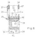
- FIGS. 5b and 6 show a magazine arrangement 26 for receiving the receptacle 8 pivoted according to arrow 23 and for emptying the box which is now at an angle on its upper side. It has a cover 31 which can be moved about an axis 27 in the direction of arrow 28 against the action of a tension spring 29 and which has prong-shaped projections 32 which are slightly curved upwards at its lower end 31a.
- the tension spring 29 engages a lever 33 which, like the cover 31, can be pivoted about the axis 27 mounted in the side walls 34.
- An electromagnetic vibrator 36 is attached to the cover 31 so that it can vibrate it.
- the side walls 34 are fastened to a holding surface 38 by means of a spacer 37.
- a discharge conveyor in the form of a trough drum 41 is rotatably mounted in the side surfaces 34 and can be driven by a step-by-step electric motor 43 in the direction of arrow 44 by the distance between two troughs 46. It is also possible to provide a different drive or the bowl drum 41 by hand, for. B. by means of a hand crank.
- the troughs 46 of the trough drum 41 have recesses 47 corresponding to the projections 32 of the cover 31.
- FIG. 7 shows the receptacle 8 pivoted about the axis 22 from an initial position (FIG. 5a) into its emptying position with the box 1 containing the filter sleeves 4.
- the bottom 9 shown in FIG. 5a and the auxiliary lid 11 are now interchanged in the lid or auxiliary bottom.
- the pin 21 fastened to the auxiliary base 11 presses the cover 31 of the magazine arrangement 26 somewhat downwards.
- the bowl drum 41 is still stationary. Now the auxiliary base 11 of the receptacle 8 is moved by hand according to FIG.
- FIG. 9 shows an auxiliary base 11 which has been pulled off even further and thus a cover 31 which is pressed even further downward, the projections 32 of which now dip into the recesses 47 of the recesses 46 of the recessed drum 41.
- the auxiliary floor 11 and the cover 31 in their end positions.
- the cover 31 forms the left boundary wall of the actual magazine 40 of the magazine arrangement 26, the right boundary wall of which forms the wall of the box 1 adjacent to the side wall 12 in a very advantageous manner.
- the removal of the cigarette tubes 4 from the magazine 40 can now begin.
- the bowl drum 41 is set in a stepwise rotating movement.
- the cigarette tubes 4 transferred into the troughs 46 are conveyed according to arrow 44 to a filling position 51, in which compressed tobacco portions are filled into the cigarette tubes 4 in a manner not known per se during the conveying stoppages.
- the cigarettes are now finished and can be removed.
- the cover 31 can be vibrated by the vibrator 36, which causes the movements of the filter sleeves 4 in the magazine arrangement 26 and their transfer into the troughs 46 of the trough drum 41 relieved.
- the base 11 is pushed back into its starting position in the opposite direction of the arrow 50.
- the cover 31 of the magazine arrangement 26 is pulled back by the tension spring 29 into its starting position shown in FIG. 5b.
- the receptacle 8 is then pivoted about the axis 22 in the opposite position to the arrow 23 into the starting position shown in FIG.
- the empty box 1 is removed and a new box is inserted in the manner described.
- an emptying process into the magazine arrangement 26 can take place again.
- the described advantageous coupling of the pulling-off movement of the auxiliary floor 11 and the lowering of the cover 31 the pin 21, ie the kinematic connection of the two components, can be replaced by separate movements according to the invention. It is then z. B. first the auxiliary floor 11 moves in the direction of arrow 50 and then the cover 31 is pivoted about the axis 27.
- the emptying arrangement according to the invention can also work without the pivoting device shown in FIG. 5a.
- the box 1 is then covered with the auxiliary base 11 and placed directly on the magazine arrangement 26, where it is held by movable side walls.
- the tobacco portions to be filled in can advantageously be formed and supplied in a manner as described in the applicant's application with the internal file number 19, text: Feeding filter sleeves-tobacco, title: Method and device for forming portions from shredded smoking material .
Landscapes
- Manufacturing Of Cigar And Cigarette Tobacco (AREA)
- Basic Packing Technique (AREA)
- Wrapping Of Specific Fragile Articles (AREA)
Abstract
Description
Die Erfindung betrifft ein Verfahren zum Entleeren eines mit zylindrischen Gegenständen, vorzugsweise Zigarettenhülsen, gefüllten Behälters in eine Magazinanordnung.The invention relates to a method for emptying a container filled with cylindrical objects, preferably cigarette tubes, into a magazine arrangement.
Die Erfindung betrifft eine Vorrichtung zum Entleeren eines mit zylindrischen Gegenständen, vorzugsweise Zigarettenhülsen, gefüllten Behälters in eine Magazinanordnung.The invention relates to a device for emptying a container filled with cylindrical objects, preferably cigarette tubes, into a magazine arrangement.
Unter dem Begriff "gefüllt" ist nicht zu verstehen, daß der Behälter randvoll mit Gegenständen gefüllt ist, obwohl dieser Fall für die Erfindung die größte Bedeutung hat.The term "filled" is not to be understood as meaning that the container is filled to the brim with objects, although this case is of the greatest importance for the invention.
Die der Erfindung zugrundeliegende Aufgabe besteht darin, empfindliche Gegenstände, wie sie Zigarettenhülsen darstellen, schonend aus ihren Behältern zu entleeren.The object on which the invention is based is to gently empty sensitive objects, such as those represented by cigarette tubes, from their containers.
Die Lösung des Verfahrens gemäß der Erfindung besteht darin, daß auf den oben offenen Behälter ein Hilfsdeckel aufgebracht wird, daß danach der Behälter geschwenkt wird, wodurch der Hilfsdeckel über eine in einem Winkel von weniger als 90° zur Horizontalen, vorzugsweise in einem Winkel von etwa 45° angeordnete Abdeckung der Magazinanordnung gelangt und dort einen Hilfsboden bildet, daß danach der Hilfsboden entfernt und die Abdeckung nach unten bewegt wird, wobei sie zu einem Teil des die Zigarettenhülsen aufnehmenden Magazins wird.
Vorteilhafte Weiterbildungen und weitere Ausgestaltungen des Verfahrens gemäß der Erfindung sind den untergeordneten Verfahrensansprüchen zu entnehmen.
Die eingangs genannte Vorrichtung ist gemäß der Erfindung gekennzeichnet durch eine Schwenkvorrichtung für den mit einem Hilfsdeckel versehenen Behälter, dessen Hilfsdeckel sich nach einer Verschwenkung über einer in einem Winkel von weniger als 90°, vorzugsweise in einem Winkel von etwa 45°, zu der Horizontalen angeordneten Abdeckung der Magazinanordnung befindet, wobei er einen entfernbaren Hilfsboden für den Behälter bildet und gekennzeichnet durch eine Absenkvorrichtung für die Abdeckung.
Vorteilhafte Weiterbildungen und weitere Ausgestaltungen der Vorrichtung gemäß der Erfindung sind den untergeordneten Vorrichtungsansprüchen zu entnehmen.The solution of the method according to the invention is that an auxiliary lid is applied to the open top container, that the container is then pivoted, whereby the auxiliary lid over an angle of less than 90 ° to the horizontal, preferably at an angle of about 45 ° arranged cover of the magazine assembly arrives and forms an auxiliary base there that the auxiliary base is then removed and the cover is moved downward, where it becomes part of the magazine receiving the cigarette tubes.
Advantageous further developments and further refinements of the method according to the invention can be found in the subordinate method claims.
The device mentioned at the outset is characterized according to the invention by a pivoting device for the an auxiliary cover provided container, the auxiliary cover of which is after pivoting over a cover of the magazine arrangement arranged at an angle of less than 90 °, preferably at an angle of approximately 45 °, wherein it forms a removable auxiliary base for the container and characterized by a lowering device for the cover.
Advantageous further developments and further refinements of the device according to the invention can be found in the subordinate device claims.
Die mit der Erfindung verbundenen Vorteile bestehen einmal darin, daß empfindliche zylindrische Gegenstände, wie Zigarettenhülsen, schonend, d. h. ohne Gefahr von Beschädigungen, aus ihren Behältern entfernt werden, beispielsweise in ein Magazin, aus dem sie dann vereinzelt abgefördert werden können, beispielsweise zu einer Füllvorrichtung, in der Tabakportionen eingefüllt werden.
Ein weiterer Vorteil der Erfindung besteht darin, daß die Gegenstände beim Entleeren nicht ihre gegenseitige Ausrichtung in paralleler Lage verlieren; ist dies der Fall, legen sich also einzelne oder mehrere Zigarettenhülsen quer, dann ist außer mit Beschädigungen auch mit Störungen beim Abtransport zu rechnen.
Schließlich zeichnen sich Verfahren und Vorrichtung gemäß der Erfindung dadurch aus, daß die Funktionsabläufe einfach und apparativ wenig aufwendig sind.The advantages associated with the invention consist in the fact that sensitive cylindrical objects, such as cigarette tubes, are removed gently from their containers, for example into a magazine from which they can then be removed, for example to a filling device, without risk of damage in which tobacco portions are filled.
Another advantage of the invention is that the objects do not lose their mutual alignment in a parallel position when emptied; if this is the case, i.e. if one or more cigarette tubes are lying crosswise, then damage can also be expected, as well as malfunctions during removal.
Finally, the method and device according to the invention are characterized in that the functional sequences are simple and inexpensive in terms of equipment.
Die Erfindung wird anhand eines Ausführungsbeispieles näher erläutert.The invention is explained in more detail using an exemplary embodiment.
Es zeigen:
Figur 1- eine zahlreiche Zigarettenhülsen enthaltende Schachtel in geschlossenem Zustand und perspektivischer Darstellung,
Figur 2- eine Schachtel gemäß
Figur 1 in halbgeöffnetem Zustand, Figur 3- eine weniger Zigarettenhülsen enthaltende Schachtel in geschlossenem Zustand und perspektivischer Darstellung,
Figur 4- eine Schachtel gemäß
Figur 3 in halbgeöffnetem Zustand, - Figur 5
- eine im Schnitt dargestellte schwenkbare Schachtelaufnahme (Figur 5a) sowie eine im Schnitt dargestellte Magazinanordnung zum Aufnehmen von aus einer geschwenkten Schachtel austretenden Zigarettenhülsen (Figur 5b), jeweils in Ausgangsposition,
Figur 6- eine Ansicht auf die Magazinanordnung der Figur 5b, die entsprechend den Schnittlinien A-A, B-B teilweis geschnitten ist,
Figur 7- die auf die Magazinanordnung geschwenkte alle Zigarettenhülsen noch enthaltende Schachtelaufnahme (teilweise weggebrochen),
Figur 8- die Schachtelaufnahme und die Magazinanordnung zu Beginn der Schachtelentleerung und des Einfüllens von Zigarettenhülsen in die Magazinanordnung (teilweise weggebrochen),
Figur 9- die gegenüber
Figur 8 weiter geöffnete Schachtelaufnahme und Magazinanordnung (teilweise weggebrochen), - Figur 10
- die gegenüber den
Figuren 8 und 9 noch weiter geöffnete Schachtelaufnahme und Magazinanordnung im Zustand maximaler Öffnung (teilweise weggebrochen).
- Figure 1
- a box containing numerous cigarette tubes in the closed state and in perspective,
- Figure 2
- 1 in a half-opened state,
- Figure 3
- a box containing fewer cigarette tubes in the closed state and in perspective,
- Figure 4
- 3 in a half-opened state,
- Figure 5
- 4 shows a pivotable box holder (FIG. 5a) and a magazine arrangement shown in section for receiving cigarette tubes (FIG. 5b) emerging from a swiveled box, each in the starting position,
- Figure 6
- 5b is a view of the magazine arrangement of FIG. 5b, which is partially cut according to the section lines AA, BB,
- Figure 7
- the box receptacle which has been pivoted onto the magazine arrangement and contains all the cigarette tubes (partially broken away),
- Figure 8
- the box holder and the magazine arrangement at the beginning of the box emptying and the filling of cigarette tubes into the magazine arrangement (partially broken away),
- Figure 9
- the box receptacle and magazine arrangement which is further open compared to FIG. 8 (partially broken away),
- Figure 10
- the box receptacle and magazine arrangement, which is even more open than in FIGS. 8 and 9, in the state of maximum opening (partially broken away).
Die Figuren 1 und 2 zeigen einen geschlossenen bzw. halbgeöffneten Behälter in Form einer Schachtel 1 mit Klappdeckel 2, an dem eine relativ zum Deckel 2 bewegbare Lasche 3 angebracht ist. Die Schachtel enthält eine größere Anzahl (z. B. zweihundert) Zigarettenhülsen 4, die jeweils aus Hohlzylindern 6 aus Zigarettenpapier und damit verbundenen Filterstopfen 7 bestehen. Die Zigarettenhülsen brauchen keine Filterstopfen aufzuweisen; sie bestehen dann nur aus Hohlzylindern aus Zigarettenpapier.
Die Figuren 3 und 4 zeigen einen geschlossenen bzw. halbgeöffneten Behälter in Form einer Schachtel 1a, wie sie in den Figuren 1 und 2 dargestellt ist; der Unterschied besteht darin, daß die Schachtel 1a erheblich schmaler ist, beispielsweise nur zwanzig Zigarettenhülsen 4a mit oder ohne Filterstopfen 7a enthält.
Die dargestellten Behälter 1 und 1a sind vollständig mit Gegenständen, also Zigarettenhülsen 4 bzw. 4a, gefüllt. Im Prinzip brauchen die Behälter aber nicht voll gefüllt zu sein.
In die Zigarettenhülsen werden in nicht dargestellter Weise verdichtete Portionen aus Fasern, die aus Schnittabak (Blatttabak, Rippentabak, Folientabak) oder sonstigem Rauchmaterial bestehen können, zur Herstellung von Zigaretten mit oder ohne Filter eingebracht. Hierzu kann eine Anzahl von Zigarettenhülsen, also z. B. ein Schachtelinhalt, in einen Magazinbehälter eingebracht werden, aus dem die Hülsen vereinzelt entnommen und in eine Füllposition verbracht werden, in denen die Tabakportionen eingefüllt werden.
Die Zigarettenhülsen 4, 4a sind wegen des sehr dünnen Zigarettenpapiers empfindlich, so daß sie beim manipulieren von Hand leicht beschädigt oder zerstört werden. Werden sie aus einer Schachtel einfach in den Magazinbehälter ausgekippt, so besteht neben der Beschädigungsgefahr noch die zusätzliche Gefahr, daß die Hülsen ihre Ausrichtung verlieren, z. B. sich quer legen, so daß der Austragvorgang gestört wird.FIGS. 1 and 2 show a closed or half-opened container in the form of a
Figures 3 and 4 show a closed or half-opened container in the form of a box 1a, as shown in Figures 1 and 2; the difference is that the box 1a is considerably narrower, for example contains only twenty
The
Compressed portions of fibers, which can consist of cut tobacco (leaf tobacco, rib tobacco, foil tobacco) or other smoking material, are introduced into the cigarette tubes in a manner not shown for the production of cigarettes with or without a filter. A number of cigarette tubes, e.g. B. a box content, are placed in a magazine container, from which the sleeves are removed individually and placed in a filling position, in which the tobacco portions are filled.
The
In den Figuren 5 bis 10 ist dargestellt, wie die Zigarettenhülsen 4, 4a aus den Schachteln 1 bzw. 1a in eine Magazinanordnung überführt werden können, ohne beschädigt zu werden oder sich quer zu legen, aus der sie dann vereinzelt entnommen und zu einer Füllposition abgefördert werden.
Figur 5a zeigt eine Aufnahme 8 für eine Schachtel 1 für eine größere Anzahl von Zigarettenhülsen 4, z. B. von zweihundert Stück. Die Aufnahme 8 weist einen Boden 9, einen Hilfsdeckel 11, Seitenwände 12, 13 sowie Stirnwände 14 auf, von denen die vordere nicht sichtbar ist. Zum Anpassen der Aufnahme 8 an Schachteln unterschiedlicher Größen ist die Seitenwand 13 in Richtung des Doppelpfeils 16 verschiebbar. Vor dem Einsetzen einer Schachtel 1 wird der Hilfsdeckel 11 in einer Schiene 17 in Richtung des Pfeils 18 in Offenstellung verschoben. Die Schachtel 1 wird von Hand in die Aufnahme 8 eingesetzt, wobei zunächst der Klappdeckel 2 abgeschwenkt und mit der Lasche 3 nach hinten abgebogen wird. Die Lasche 3 wird beim Aufsetzen der Schachtel 1 auf dem Boden 9, das so erfolgt, daß die Filterstopfen 7 auf den Betrachter zu, in der Zeichnung also nach vorn, zu liegen kommen, in einem Schlitz zwischen hinterer Stirnwand 14 und Boden 9 fixiert. Danach wird der Hilfsdeckel 11 in Richtung des Pfeils 19 in Schließstellung zurückbewegt. An dem Hilfsdeckel 11 ist ein Zapfen 21, z. B. aus Kunststoff, befestigt, dessen Zweck anschließend erläutert wird.
Die Aufnahme 8 ist mit der Schachtel 1 und den Zigarettenhülsen 4 aus der in Figur 5a dargestellten Ausgangsposition, in der die Schachtel auf die beschriebene Weise von Hand eingesetzt wurde, um eine Achse 22 von Hand oder durch einen geeigneten Antrieb entsprechend Pfeil 23 um einen Winkel von etwa 135° in eine in den Figuren 5b und 6 dargestellte Entleerungsposition schwenkbar, in der sie in den Figuren 7 bis 10 gezeigt ist. Zur Aufnahme einer weiteren Schachtel ist die entleerte Aufnahme 8 entgegen der Richtung des Pfeils 23 in die in Figur 5a gezeichnete Position zurückschwenkbar. Der Verschwenkwinkel braucht nicht 135° zu sein. Er kann von diesem Wert abweichen und z. B. zwischen 120° und 150° liegen. Von Bedeutung ist lediglich, daß Aufnahme- und Magazinanordnung nach dem Verschwenken in einem Winkel unter 90° zur Horizontalen geneigt sind, vorteilhaft in einem Winkel von etwa 45°.FIGS. 5 to 10 show how the
Figure 5a shows a
The
In den Figuren 5b und 6 ist eine Magazinanordnung 26 zum Aufnehmen der entsprechend Pfeil 23 verschwenkten Aufnahme 8 und zum Entleeren der jetzt schräg auf ihrer Oberseite stehenden Schachtel dargestellt. Sie weist eine um eine Achse 27 in Richtung des Pfeils 28 gegen die Wirkung einer Zugfeder 29 bewegbare Abdeckung 31 auf, die an ihrem unteren Ende 31a zinkenförmige leicht nach oben gebogene Vorsprünge 32 aufweist. Die Zugfeder 29 greift an einem Hebel 33 an, der ebenso wie die Abdeckung 31 um die in Seitenwänden 34 gelagerte Achse 27 schwenkbar ist. Ein elektromagnetischer Vibrator 36 ist so an der Abdeckung 31 befestigt, daß er diese in Schwingungen versetzen kann. Die Seitenwände 34 sind mittels eines Distanzstückes 37 an einer Haltefläche 38 befestigt.
Unterhalb des unteren Endes 31a der Abdeckung 31 ist ein Abförderer in Form einer Muldentrommel 41 in den Seitenflächen 34 drehbar gelagert und von einem schrittweise antreibbaren Elektromotor 43 in Richtung des Pfeils 44 um jeweils die Distanz zwischen zwei Mulden 46 antreibbar. Es ist auch möglich, einen anderen Antrieb vorzusehen oder die Muldentrommel 41 von Hand, z. B. mittels einer Handkurbel, anzutreiben. Die Mulden 46 der Muldentrommel 41 weisen Ausnehmungen 47 entsprechend den Vorsprüngen 32 der Abdeckung 31 auf. Zwischen dem unteren Ende 31a der Abdeckung 31 und der Muldentrommel 41 befindet sich ein Distanzstück 48, das an seiner den Vorsprüngen zugewandten Seite ebenfalls mit entsprechenden Ausnehmungen 49 versehen ist.
In den Figuren 7 bis 10 ist ein Entleerungsvorgang für eine Schachtel 1 in die Magazinanordnung 26 und das Abfördern der entleerten Filterhülsen 4 beschrieben.
Figur 7 zeigt die um die Achse 22 von einer Ausgangsposition (Figur 5a) in ihre Entleerungsposition geschwenkte Aufnahme 8 mit der die Filterhülsen 4 enthaltenden Schachtel 1. Der in Figur 5a gezeigte Boden 9 und der Hilfsdeckel 11 sind nunmehr vertauscht in Deckel bzw. Hilfsboden. Der an dem Hilfsboden 11 befestigte Zapfen 21 drückt die Abdeckung 31 der Magazinanordnung 26 schon etwas nach unten. Die Muldentrommel 41 steht noch still.
Nunmehr wird von Hand entsprechend Figur 8 der Hilfsboden 11 der Aufnahme 8 in Richtung des Pfeils 50 aus seiner die auf ihm ruhenden Zigarettenhülsen 4 stützenden Stützposition bewegt, wobei der Hilfsboden 11 durch die Schiene 17 in der Aufnahme 8 geführt wird. Damit bewegt sich der Zapfen 21 ebenfalls in Richtung des Pfeils 50 und drückt die um die Achse 27 drehbare Abdeckung 31 der Magazinanordnung 26 entgegen der Wirkung der Zugfeder 29 weiter nach unten, wobei die Vorsprünge 32 der Abdeckung 31 in die entsprechenden Ausnehmungen 49 des Distanzstückes 48 eintauchen. Die ersten Filterhülsen 4 treten dabei aus der Schachtel 1 aus.
Figur 9 zeigt einen noch weiter abgezogenen Hilfsboden 11 und damit eine noch weiter nach unten gedrückte Abdeckung 31, deren Vorsprünge 32 jetzt in die Ausnehmungen 47 der Mulden 46 der Muldentrommel 41 eintauchen.
Figur 10 zeigt den Hilfsboden 11 und die Abdeckung 31 in ihren Endpositionen. In dieser Position bildet die Abdeckung 31 die linke Begrenzungswand des eigentlichen Magazins 40 der Magazinanordnung 26, dessen rechte Begrenzungswand in sehr vorteilhafter Weise die der Seitenwand 12 benachbarte Wand der Schachtel 1 bildet. Nunmehr kann die Abförderung der Zigarettenhülsen 4 aus dem Magazin 40 beginnen. Hierzu wird die Muldentrommel 41 in schrittweise drehende Bewegung versetzt. Die in die Mulden 46 übernommenen Zigarettenhülsen 4 werden entsprechend Pfeil 44 zu einer Füllposition 51 gefördert, in der während der Förderstillstände in an sich bekannter nicht dargestellter Weise verdichtete Tabakportionen in die Zigarettenhülsen 4 eingefüllt werden. Damit sind die Zigaretten fertiggestellt und können entnommen werden. Während des Abziehens des Hilfsbodens 11 und/oder der Förderung der Zigarettenhülsen 4 durch die Muldentrommel 41 kann die Abdeckung 31 von dem Vibrator 36 in Schwingungen versetzt werden, was die Bewegungen der Filterhülsen 4 in der Magazinanordnung 26 und ihre Übernahme in die Mulden 46 der Muldentrommel 41 erleichtert.
Nach Abförderung aller Zigarettenhülsen 4 aus der Magazinanordnung 26 wird der Boden 11 entgegen der Richtung des Pfeils 50 wieder in seine Ausgangslage verschoben. Die Abdeckung 31 der Magazinanordnung 26 wird dabei von der Zugfeder 29 in ihre in Figur 5b dargestellte Ausgangsposition zurückgezogen. Darauf wird die Aufnahme 8 entgegengesetzt zu Pfeil 23 um die Achse 22 in die in Figur 5a gezeigte Ausgangsposition geschwenkt, die leere Schachtel 1 entnommen und eine neue Schachtel auf die beschriebene Weise eingesetzt. Hierzu kann nach erneutem Verschwenken der Aufnahme 8 auf die beschriebene Weise wieder ein Entleerungsvorgang in die Magazinanordnung 26 erfolgen.
Die beschriebene vorteilhafte Kopplung der Abziehbewegung des Hilfsbodens 11 und der Absenkung der Abdeckung 31 über den Zapfen 21, d. h. die kinematische Verbindung beider Bauelemente, kann gemäß der Erfindung durch getrennte Bewegungen ersetzt werden. Es wird dann z. B. zunächst der Hilfsboden 11 in Richtung des Pfeils 50 bewegt und danach die Abdeckung 31 um die Achse 27 verschwenkt.
Die Entleerungsanordnung gemäß der Erfindung kann im Prinzip auch ohne die in Figur 5a gezeigte Schwenkvorrichtung arbeiten. Die Schachtel 1 wird dann mit dem Hilfsboden 11 abgedeckt und direkt auf die Magazinanordnung 26 aufgesetzt, wo sie durch heranbewegbare Seitenwände gehalten wird.
Die einzufüllenden Tabakportionen können vorteilhaft in einer Weise gebildet und zugeführt werden, wie sie in der Anmeldung der Anmelderin mit der internen Aktennummer 19, Stw.: Filterhülsen stopfen-Tabak zuführen, Titel: Verfahren und Vorrichtung zum Bilden von Portionen aus zerkleinertem Rauchmaterial, beschrieben ist.FIGS. 5b and 6 show a
Below the
FIGS. 7 to 10 describe an emptying process for a
FIG. 7 shows the
Now the
FIG. 9 shows an
FIG. 10 shows the
After all
The described advantageous coupling of the pulling-off movement of the
In principle, the emptying arrangement according to the invention can also work without the pivoting device shown in FIG. 5a. The
The tobacco portions to be filled in can advantageously be formed and supplied in a manner as described in the applicant's application with the
Claims (17)
Applications Claiming Priority (2)
| Application Number | Priority Date | Filing Date | Title |
|---|---|---|---|
| DE4433850A DE4433850A1 (en) | 1994-09-22 | 1994-09-22 | Method and device for emptying a container |
| DE4433850 | 1994-09-22 |
Publications (2)
| Publication Number | Publication Date |
|---|---|
| EP0702905A2 true EP0702905A2 (en) | 1996-03-27 |
| EP0702905A3 EP0702905A3 (en) | 1999-06-09 |
Family
ID=6528907
Family Applications (1)
| Application Number | Title | Priority Date | Filing Date |
|---|---|---|---|
| EP95114191A Withdrawn EP0702905A3 (en) | 1994-09-22 | 1995-09-09 | Process and apparatus for emptying a container |
Country Status (7)
| Country | Link |
|---|---|
| US (1) | US5730318A (en) |
| EP (1) | EP0702905A3 (en) |
| JP (1) | JPH08173131A (en) |
| CN (1) | CN1051911C (en) |
| AU (1) | AU697573B2 (en) |
| CA (1) | CA2158828A1 (en) |
| DE (1) | DE4433850A1 (en) |
Cited By (1)
| Publication number | Priority date | Publication date | Assignee | Title |
|---|---|---|---|---|
| CN103144804A (en) * | 2013-03-20 | 2013-06-12 | 广东喜之郎集团有限公司 | Single suction tube throwing device |
Families Citing this family (13)
| Publication number | Priority date | Publication date | Assignee | Title |
|---|---|---|---|---|
| DE19521180A1 (en) * | 1995-06-10 | 1996-12-12 | Chilinov Sarl | Method and device for filling tubes with smoke material |
| GB9816796D0 (en) * | 1998-08-03 | 1998-09-30 | Henrob Ltd | Improvements in or relating to fastening machines |
| US6202891B1 (en) * | 1998-10-23 | 2001-03-20 | Microbrush, Corporation | Dispenser for liquid applicator |
| US20030219331A1 (en) * | 2002-04-17 | 2003-11-27 | Brown Thomas M. | Control system and unloading method |
| CN102717934B (en) * | 2012-06-13 | 2014-08-20 | 昆明鼎承科技有限公司 | Automatic strip-product packer |
| CN103040108B (en) * | 2013-01-15 | 2015-04-08 | 昆明鼎承科技有限公司 | Pulling plate type magazine discharging device |
| US9953140B2 (en) * | 2013-03-15 | 2018-04-24 | Intent Solutions, Inc. | Systems, methods, and apparatuses for securely dispensing one or more prescribed substances to a securely identified intended user |
| US9386871B2 (en) * | 2013-09-05 | 2016-07-12 | Antonio Domit | Multi-flap box for soda straws |
| EP2901871A1 (en) * | 2014-01-31 | 2015-08-05 | Philip Morris Products S.A. | Multi-segment filter tube |
| WO2018200306A1 (en) * | 2017-04-24 | 2018-11-01 | Desktop Metal, Inc. | Rod feeder for three-dimensional (3d) printing |
| EP3813560B1 (en) * | 2018-06-29 | 2022-08-24 | Philip Morris Products S.A. | Method and apparatus to cast a web of material containing alkaloids |
| CN109878787A (en) * | 2019-02-26 | 2019-06-14 | 成都慧晶机械设备有限公司 | A kind of semi-automatic dress smoke machine |
| CN113273720B (en) * | 2021-07-26 | 2021-10-08 | 苏州鼎纳自动化技术有限公司 | Cigarette filter tip feed mechanism |
Family Cites Families (10)
| Publication number | Priority date | Publication date | Assignee | Title |
|---|---|---|---|---|
| US636413A (en) * | 1899-06-12 | 1899-11-07 | Isaac L Solomon | Match-safe. |
| US727207A (en) * | 1902-06-26 | 1903-05-05 | William J Rush | Vending-machine. |
| US1682215A (en) * | 1927-05-16 | 1928-08-28 | Warren L Colby | Dispensing device |
| US2977023A (en) * | 1958-05-09 | 1961-03-28 | Meyer Moshe Norbert | Apparatus for releasing consumer articles |
| US3960299A (en) * | 1975-06-12 | 1976-06-01 | Maryland Cup Corporation | Industrial straw dispensing carton |
| GB1592760A (en) * | 1976-12-03 | 1981-07-08 | Molins Ltd | Apparatus for unloading rod-like articles from trays |
| US4324523A (en) * | 1980-04-25 | 1982-04-13 | Zablocky William J | System for handling tubular containers, including apparatus and cases therefor |
| DE3407301A1 (en) * | 1984-02-29 | 1984-10-04 | Josef 5350 Euskirchen Miesen | Automatic filter cigarette filling machine |
| JP2621910B2 (en) * | 1988-03-30 | 1997-06-18 | 株式会社クボタ | vending machine |
| US5351856A (en) * | 1992-10-28 | 1994-10-04 | Laidlaw Ronald W | Vending machine for individual cigarettes |
-
1994
- 1994-09-22 DE DE4433850A patent/DE4433850A1/en not_active Withdrawn
-
1995
- 1995-09-09 EP EP95114191A patent/EP0702905A3/en not_active Withdrawn
- 1995-09-14 US US08/528,239 patent/US5730318A/en not_active Expired - Fee Related
- 1995-09-18 JP JP7238720A patent/JPH08173131A/en not_active Withdrawn
- 1995-09-19 AU AU31759/95A patent/AU697573B2/en not_active Ceased
- 1995-09-21 CA CA002158828A patent/CA2158828A1/en not_active Abandoned
- 1995-09-22 CN CN95118413A patent/CN1051911C/en not_active Expired - Fee Related
Non-Patent Citations (1)
| Title |
|---|
| None |
Cited By (1)
| Publication number | Priority date | Publication date | Assignee | Title |
|---|---|---|---|---|
| CN103144804A (en) * | 2013-03-20 | 2013-06-12 | 广东喜之郎集团有限公司 | Single suction tube throwing device |
Also Published As
| Publication number | Publication date |
|---|---|
| CN1051911C (en) | 2000-05-03 |
| JPH08173131A (en) | 1996-07-09 |
| US5730318A (en) | 1998-03-24 |
| AU697573B2 (en) | 1998-10-08 |
| DE4433850A1 (en) | 1996-03-28 |
| CA2158828A1 (en) | 1996-03-23 |
| AU3175995A (en) | 1996-04-04 |
| CN1130491A (en) | 1996-09-11 |
| EP0702905A3 (en) | 1999-06-09 |
Similar Documents
| Publication | Publication Date | Title |
|---|---|---|
| DE19945808B4 (en) | Method and device for sequential emptying of containers | |
| EP2805890B1 (en) | Method and device for completing (tobacco) bags with roll tab | |
| EP0702905A2 (en) | Process and apparatus for emptying a container | |
| EP0224017A1 (en) | Device in packaging machines for the pre-arranged feeding and depositing of small articles to be packaged, such as tablets, capsules, dragées or the like | |
| DE2817094A1 (en) | DEVICE FOR COMPRESSING AND PACKING ITEMS | |
| EP0970626A1 (en) | A plurality of wrappers filled with tobacco for making cigarettes | |
| DE3316176A1 (en) | DEVICE FOR EDUCATION AND REMOVAL OF TOBACCO PORTIONS | |
| DE102008015082A1 (en) | Method and device for producing bag packages | |
| DE3338390A1 (en) | AUTOMATIC FEEDER | |
| DE2648721C2 (en) | Method for filling chocolates into a box and device for carrying out the method | |
| DE102004055629A1 (en) | Apparatus and method for successively emptying containers filled with articles | |
| DE3347344A1 (en) | AUTOMATIC MACHINE FOR PACKING CIGARETTE IN HARD BOXES | |
| DE3639982A1 (en) | MACHINE FOR PACKAGING ITEMS IN GROUPS | |
| DE2347004A1 (en) | DEVICE FOR OPENING CORRUGATED CARDBOARD BOXES | |
| DE2458394A1 (en) | DEVICE FOR TRANSPORTING A PRE-DETERMINED NUMBER OF ITEMS AND USING SUCH DEVICE | |
| DE4447794C2 (en) | Method of filling cigarette paper sleeve with tobacco | |
| DE10046127A9 (en) | Filling device for micro-powder has dosing device with rotary dosing supplied from region of supply chamber with uniform distribution of micro-powder | |
| DE1611623A1 (en) | Device for the production of an upper or lower part of a box from a blank, preferably made of thermoplastic material | |
| EP0382252B1 (en) | Apparatus for filling bags with bulky goods | |
| DE2751953A1 (en) | Filling pleated transporting carton for cups or tins - by initially putting stacked cups into auxiliary container | |
| DE3390180T1 (en) | Automatic feeding device | |
| EP0697339B1 (en) | Method and device for manufacturing a display package and the correspondingly manufactured display package | |
| DE2050403A1 (en) | Device for processing eggs, in particular chicken eggs | |
| DE6752348U (en) | DEVICE FOR PACKAGING ARTICLES | |
| DE2356884C3 (en) | Insertion device |
Legal Events
| Date | Code | Title | Description |
|---|---|---|---|
| PUAI | Public reference made under article 153(3) epc to a published international application that has entered the european phase |
Free format text: ORIGINAL CODE: 0009012 |
|
| AK | Designated contracting states |
Kind code of ref document: A2 Designated state(s): AT BE CH DE DK ES FR GB IT LI NL SE |
|
| PUAL | Search report despatched |
Free format text: ORIGINAL CODE: 0009013 |
|
| AK | Designated contracting states |
Kind code of ref document: A3 Designated state(s): AT BE CH DE DK ES FR GB IT LI NL SE |
|
| 17P | Request for examination filed |
Effective date: 19991125 |
|
| GRAG | Despatch of communication of intention to grant |
Free format text: ORIGINAL CODE: EPIDOS AGRA |
|
| 17Q | First examination report despatched |
Effective date: 20010222 |
|
| STAA | Information on the status of an ep patent application or granted ep patent |
Free format text: STATUS: THE APPLICATION IS DEEMED TO BE WITHDRAWN |
|
| 18D | Application deemed to be withdrawn |
Effective date: 20010403 |