EP0703024A2 - Dispositif de serrage de pièces ou pour l'enfoncement de boulons - Google Patents
Dispositif de serrage de pièces ou pour l'enfoncement de boulons Download PDFInfo
- Publication number
- EP0703024A2 EP0703024A2 EP95113074A EP95113074A EP0703024A2 EP 0703024 A2 EP0703024 A2 EP 0703024A2 EP 95113074 A EP95113074 A EP 95113074A EP 95113074 A EP95113074 A EP 95113074A EP 0703024 A2 EP0703024 A2 EP 0703024A2
- Authority
- EP
- European Patent Office
- Prior art keywords
- cylinder
- piston
- holding
- guide
- housing
- Prior art date
- Legal status (The legal status is an assumption and is not a legal conclusion. Google has not performed a legal analysis and makes no representation as to the accuracy of the status listed.)
- Withdrawn
Links
Images

Classifications
-
- B—PERFORMING OPERATIONS; TRANSPORTING
- B21—MECHANICAL METAL-WORKING WITHOUT ESSENTIALLY REMOVING MATERIAL; PUNCHING METAL
- B21J—FORGING; HAMMERING; PRESSING METAL; RIVETING; FORGE FURNACES
- B21J15/00—Riveting
- B21J15/38—Accessories for use in connection with riveting, e.g. pliers for upsetting; Hand tools for riveting
- B21J15/42—Special clamping devices for workpieces to be riveted together, e.g. operating through the rivet holes
-
- B—PERFORMING OPERATIONS; TRANSPORTING
- B25—HAND TOOLS; PORTABLE POWER-DRIVEN TOOLS; MANIPULATORS
- B25B—TOOLS OR BENCH DEVICES NOT OTHERWISE PROVIDED FOR, FOR FASTENING, CONNECTING, DISENGAGING, OR HOLDING
- B25B27/00—Hand tools, specially adapted for fitting together or separating parts or objects whether or not involving some deformation, not otherwise provided for
- B25B27/02—Hand tools, specially adapted for fitting together or separating parts or objects whether or not involving some deformation, not otherwise provided for for connecting objects by press fit or detaching same
- B25B27/026—Hand tools, specially adapted for fitting together or separating parts or objects whether or not involving some deformation, not otherwise provided for for connecting objects by press fit or detaching same fluid driven
-
- B—PERFORMING OPERATIONS; TRANSPORTING
- B25—HAND TOOLS; PORTABLE POWER-DRIVEN TOOLS; MANIPULATORS
- B25B—TOOLS OR BENCH DEVICES NOT OTHERWISE PROVIDED FOR, FOR FASTENING, CONNECTING, DISENGAGING, OR HOLDING
- B25B27/00—Hand tools, specially adapted for fitting together or separating parts or objects whether or not involving some deformation, not otherwise provided for
- B25B27/02—Hand tools, specially adapted for fitting together or separating parts or objects whether or not involving some deformation, not otherwise provided for for connecting objects by press fit or detaching same
- B25B27/04—Hand tools, specially adapted for fitting together or separating parts or objects whether or not involving some deformation, not otherwise provided for for connecting objects by press fit or detaching same inserting or withdrawing keys
-
- B—PERFORMING OPERATIONS; TRANSPORTING
- B25—HAND TOOLS; PORTABLE POWER-DRIVEN TOOLS; MANIPULATORS
- B25B—TOOLS OR BENCH DEVICES NOT OTHERWISE PROVIDED FOR, FOR FASTENING, CONNECTING, DISENGAGING, OR HOLDING
- B25B27/00—Hand tools, specially adapted for fitting together or separating parts or objects whether or not involving some deformation, not otherwise provided for
- B25B27/02—Hand tools, specially adapted for fitting together or separating parts or objects whether or not involving some deformation, not otherwise provided for for connecting objects by press fit or detaching same
- B25B27/10—Hand tools, specially adapted for fitting together or separating parts or objects whether or not involving some deformation, not otherwise provided for for connecting objects by press fit or detaching same inserting fittings into hoses
Definitions
- the invention relates to a device for mutually bracing components or pressing bolts or rivets into one or more components, with a pressure-actuated piston-cylinder unit, the piston of which is connected to a piston rod and the cylinder of which can be extended or retracted.
- the invention has for its object to provide a device for mutually bracing components or pressing bolts or rivets, which is suitable as a hand-held device and can absorb high press-in forces, whereby a pressure-operated piston-cylinder unit is to be used, which is a commercially available component is.
- This object is achieved in that two mutually adjustable holding elements are provided, that the first holding element is connected to the piston rod by means of a guide element, that the cylinder has a cylindrical outer surface on which the guide element is guided, and that the second holding element to the cylinder is held immobile.
- the use of the outer jacket of the commercially available cylinder of the piston-cylinder unit as a bearing surface creates a bearing that allows the highest Press-in forces or clamping forces can be achieved.
- the outer surface of the cylinder is used as a plain bearing.
- An adjusting unit is known from DE 33 30 933 A1, in which a first bearing element contains a cylinder cavity in which a piston is guided so as to be adjustable. This control element is overlapped by a second control element. There is a roller guide between the two. The piston rod engages the second actuating element and adjusts it to the first actuating element. The greater the extension length of the piston rod, the shorter the guide length.
- the guide length does not change with the adjustment movement.
- Another advantage is that an inexpensive standard piston-cylinder unit can be used.
- the second holding element is preferably assigned to a housing in which the cylinder is received and supported.
- the housing is also proposed to provide the housing with a guide on which the guide element is additionally supported.
- This guide can be designed such that it only supports the guide element in the adjustment range in which the particularly high press-in or clamping forces occur, since it is a statically overdetermined support or guide. This is however, only effective in the direction of force and only effective if the play in the main guide on the cylinder and its support in the housing has been eliminated due to the high forces due to elastic deformation. This has a favorable influence on the tool dimensions.
- the holding elements have holding surfaces which are arranged in two parallel planes, which intersect the actuating axis of the piston-cylinder unit at right angles and, moreover, are arranged on one side eccentrically to the actuating axis.
- the guide is preferably arranged offset in the same direction from the actuating axis as the holding surfaces.
- the cylinder lies with its piston-side base in the housing.
- the bottom can be supported against the inner surfaces of a housing wall.
- the banjo bolt containing a pressure medium channel.
- the banjo bolt is screwed into a through hole in the bottom of the cylinder.
- the pressure medium channel is used to supply pressure medium to the piston-side cylinder space of the cylinder.
- the piston-cylinder unit is preferably designed as a one-sided piston-cylinder unit, wherein it can be acted upon with pressure medium for an actuating direction and has a return spring for adjustment in the opposite direction of this actuating direction.
- the piston-cylinder unit is designed as a hydraulically acting piston-cylinder unit.
- pneumatic actuation is also possible.
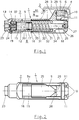
- the press-in device 1 serves to mount a flange connection 2, i.e. to bring a first flange 3 with a second flange 4 firmly together.
- a flange connection 2 i.e. to bring a first flange 3 with a second flange 4 firmly together.
- circumferentially distributed connecting elements 5 one of which is shown.
- the connecting element 5 comprises a sleeve which is brought into operative connection with the flanges 3, 4 by a bolt 6 to be pressed in, so that these are axially braced against one another.
- the press-in device 1 serves to press the pin 6 in.
- the press-in device 1 comprises a housing 7, in which a piston-cylinder unit 8 is accommodated.
- the housing 7 has an opening 9 with an enlarged area 9a.
- the housing 7 has a second holding element 10 which is provided with a holding surface 11.
- the holding surface 11 runs in a plane which intersects the adjusting axis 12 at right angles.
- the holding surface 11 is arranged offset eccentrically to the actuating axis 12. In the illustration according to FIG. 1, the holding surface 11 is offset upwards from the actuating axis 12.
- the opening 9, 9a is arranged on the top, ie in the direction of the second holding element 10, and extends over a partial region of the length of the housing 7, starting from the second holding element 10.
- the housing 7 has a housing wall 13 which has an inner surface 14 which also extends in a plane on which the actuating axis 12 is perpendicular. Furthermore, there is an axial breakthrough centered on the actuating axis 12 in the region of the housing wall 13.
- the piston-cylinder unit 8 comprises the cylinder 15 with a cylindrical outer surface 16, the piston 17 adjustable in the cylinder 15 along the actuating axis 12 and the piston rod 18 axially connected to the piston 17. Furthermore, it comprises the base 19, which, for example, as Screw bottom is designed and is screwed sealingly into the cylinder 15 from the front end, which faces the piston 17.
- the piston-side cylinder space 20 is formed between the base 19 and the piston 17.
- the piston-side cylinder chamber 20 is used for pressurizing and adjusting the piston 17.
- the bottom 19 of the piston-cylinder unit 8 has a through bore 37 centered on the actuating axis 12, which acts as a threaded bore is designed and into which a hollow screw 23 is screwed, which is inserted through the opening in the housing wall 13 and bears with a collar against the outside of the housing wall 13, around the cylinder 15 with its bottom 19 in contact with the inner surface 14 of the housing wall 13 for support purposes.
- the hollow screw 23 has an axially continuous pressure medium channel 24, which serves to supply pressure medium to the piston-side cylinder space 20 and is intended, for example, for connection through a pressure line to a pump.
- a guide element 25 is connected to the end of the piston rod 18 which is led out of the cylinder 15.
- the guide element 25 has a web 26 to which the piston rod 18 is connected by a screw 27.
- the guide element 25 is provided with a first holding element 28 which has a holding surface 29 which extends in a plane on which the actuating axis 12 is at right angles. Furthermore, the holding surface 29 is also arranged eccentrically to the actuating axis 12.
- the holding surface 11 is shown as part of two fingers which form the holding element 10. The two fingers are arranged laterally or partially overlapping to the holding surface 29 of the first holding element 28, so that a passage is formed between the two.
- the holding element 28 has a recess 30 in the holding surface 29, which serves, for example, to receive a head of the bolt 6 in order to center it during the press-in process.
- the guide element 25 encompasses the cylinder 15. It has a bore 34 in which two guide sleeves 31 are held at a distance from one another by a spacer sleeve 32 and secured by a locking ring 33.
- the two guide sleeves 31 are made of a material with a low coefficient of friction and slide on the outer surface 16 of the cylinder 15.
- the guide element 25 thus serves to support the reaction forces introduced into the holding element 28 from the application of pressure medium to the piston-side cylinder space 20 and adjustment of the Piston rod 18, with which the guide element 25 is coupled.
- the guide surfaces 35 which are arranged parallel to the cylinder 15 and its actuating axis 12, work together with support surfaces 36 of the guide element, which bear against the corresponding guide surfaces 35 of the housing 7 on the last section of the adjustment path when the greatest forces occur.
- the adjustment in the direction of adjustment N and thus the pressing of the bolt 6 takes place, for example, starting from the position of the holding element 28 shown in broken lines to the position shown in solid lines by applying pressure medium to the piston-side cylinder space 20.
- the resetting in the direction N1 takes place after the pressurization of the piston-side cylinder chamber 20 has been released under the action of the return spring 22 , 28 take up the two flanges 3, 4 between them.
- the holding element 10 is axially supported on the flange 4, while the holding element 28 axially acts on the bolt 6 until, starting from the dashed position of the holding element 28, it is pushed so far to the right into the connecting element 5 that the holding element 28 comes into contact with its holding surface 29 has reached the end surface of the connecting element 5 or another stop surface.
Landscapes
- Engineering & Computer Science (AREA)
- Mechanical Engineering (AREA)
- Actuator (AREA)
- Automatic Assembly (AREA)
- Hand Tools For Fitting Together And Separating, Or Other Hand Tools (AREA)
Applications Claiming Priority (2)
| Application Number | Priority Date | Filing Date | Title |
|---|---|---|---|
| DE19944433911 DE4433911C1 (de) | 1994-09-23 | 1994-09-23 | Vorrichtung zum gegenseitigen Verspannen von Bauteilen oder Einpressen von Bolzen oder Nieten |
| DE4433911 | 1994-09-23 |
Publications (2)
| Publication Number | Publication Date |
|---|---|
| EP0703024A2 true EP0703024A2 (fr) | 1996-03-27 |
| EP0703024A3 EP0703024A3 (fr) | 1996-07-24 |
Family
ID=6528940
Family Applications (1)
| Application Number | Title | Priority Date | Filing Date |
|---|---|---|---|
| EP95113074A Withdrawn EP0703024A3 (fr) | 1994-09-23 | 1995-08-19 | Dispositif de serrage de pièces ou pour l'enfoncement de boulons |
Country Status (3)
| Country | Link |
|---|---|
| EP (1) | EP0703024A3 (fr) |
| JP (1) | JPH0890446A (fr) |
| DE (1) | DE4433911C1 (fr) |
Families Citing this family (1)
| Publication number | Priority date | Publication date | Assignee | Title |
|---|---|---|---|---|
| DE29615607U1 (de) * | 1996-09-09 | 1996-10-31 | Weißhaar, Angelika, 78052 Villingen-Schwenningen | Spreizvorrichtung zum Spreizen einer Federklammer |
Citations (1)
| Publication number | Priority date | Publication date | Assignee | Title |
|---|---|---|---|---|
| DE3330933A1 (de) | 1983-08-27 | 1985-03-14 | Franco 6305 Alten-Buseck Toss | Hubzylinder |
Family Cites Families (9)
| Publication number | Priority date | Publication date | Assignee | Title |
|---|---|---|---|---|
| US2183842A (en) * | 1937-03-26 | 1939-12-19 | Blackhawk Mfg Co | Hinge pin pusher |
| DE1751904U (de) * | 1957-07-13 | 1957-09-05 | Frankfurter Maschb A G Vorm Po | Mittels eines druckmediums betaetigte hubzylindereinheit. |
| US4189817A (en) * | 1978-03-03 | 1980-02-26 | Moebius Kurt Otto | Hydraulic assembly tool for tube fittings |
| CH639740A5 (de) * | 1979-07-18 | 1983-11-30 | Fischer Ag Georg | Einrichtung zur herstellung einer rohrverbindung. |
| DE3426701A1 (de) * | 1984-07-20 | 1986-01-23 | Rolf Fleischer-Harkort | Kolben-zylinder-einheit |
| DE3917382A1 (de) * | 1989-05-29 | 1990-12-06 | Opel Adam Ag | Vorrichtung zum eindruecken von spannhuelsen in die tuerscharniere eines kraftfahrzeugs |
| JP3086703B2 (ja) * | 1990-04-06 | 2000-09-11 | ロックリング コーポレイション | 管継手の改良された荷重支持装置を備えた油圧組立工具 |
| JP2875889B2 (ja) * | 1992-01-31 | 1999-03-31 | ザ ドイチュ カンパニー | 軸線方向にスエージ加工された管継手用スエージ工具 |
| JP3066934B2 (ja) * | 1992-11-05 | 2000-07-17 | 日産ディーゼル工業株式会社 | キングピン用ダストシール圧入装置 |
-
1994
- 1994-09-23 DE DE19944433911 patent/DE4433911C1/de not_active Expired - Fee Related
-
1995
- 1995-08-19 EP EP95113074A patent/EP0703024A3/fr not_active Withdrawn
- 1995-09-21 JP JP7266114A patent/JPH0890446A/ja active Pending
Patent Citations (1)
| Publication number | Priority date | Publication date | Assignee | Title |
|---|---|---|---|---|
| DE3330933A1 (de) | 1983-08-27 | 1985-03-14 | Franco 6305 Alten-Buseck Toss | Hubzylinder |
Also Published As
| Publication number | Publication date |
|---|---|
| JPH0890446A (ja) | 1996-04-09 |
| DE4433911C1 (de) | 1996-02-29 |
| EP0703024A3 (fr) | 1996-07-24 |
Similar Documents
| Publication | Publication Date | Title |
|---|---|---|
| EP0349942B1 (fr) | Etançon hydraulique en acier | |
| EP0911112A1 (fr) | Dispositif combiné de centrage et serrage actionnable par fluide sous pression, utilisable en particulier pour la construction de carrosseries automobile dans l'industrie automobile | |
| EP1700648A1 (fr) | Dispositif d' élargissement de corps creux | |
| EP0106030B1 (fr) | Machine à cintrer avec mandrin | |
| DE2656210A1 (de) | Bohrstranghalter in einer gesteinsbohrmaschine | |
| DE3151275A1 (de) | Befestigungsvorrichtung fuer werkzeuge | |
| EP3025824B1 (fr) | Outil hydraulique mobil | |
| DE102009049920A1 (de) | Spannvorrichtung | |
| EP0100334B1 (fr) | Appareil de pressage de parties tubulaires | |
| EP1494827B1 (fr) | Dispositif de deformation plastique de pieces a usiner | |
| EP0619153B1 (fr) | Outil évaseur pour pièces à usiner creuses | |
| EP2177296A1 (fr) | Dispositif de serrage extensible | |
| DE2232872C3 (de) | Vorrichtung zur Begrenzung einer durch Hebel wirkung zu übertragenden Kraft | |
| EP0703024A2 (fr) | Dispositif de serrage de pièces ou pour l'enfoncement de boulons | |
| DE19511447C2 (de) | Vorrichtung zum Ausformen des Endbereiches eines Rohres für die Verwendung in Schraubverbindungen | |
| DE4011178C2 (de) | Gelenkstativ, insbesondere Meßstativ | |
| DE4119624C1 (en) | Positive sheet metal plate joining mechanism - has joining press with plunger and die with plunger movable towards and away from die | |
| DE3426997C2 (de) | Hochdruck-Hubkolbenmaschine | |
| DE3820513C1 (en) | Hydraulic clamping device | |
| DE202016005535U1 (de) | Abstützelement, insbesondere zum Abstützen eines Werkstücks | |
| DE8807923U1 (de) | Vorrichtung zur Kraftaufbringung, insbesondere Montagevorrichtung für eine Rohrverbindungskupplung auf Verpressungsbasis | |
| DE10153336A1 (de) | Druckmittelzylinder mit einer Einrichtung zur Verstellung des Kolbenhubs | |
| DE9313787U1 (de) | Druckmittel-betätigbare Hubeinrichtung | |
| EP1531027A1 (fr) | Elément de serrage et procédé pour serrer des pièces, des outils, des moules ou des dispositifs | |
| EP1683974B1 (fr) | Elément de fixation |
Legal Events
| Date | Code | Title | Description |
|---|---|---|---|
| PUAI | Public reference made under article 153(3) epc to a published international application that has entered the european phase |
Free format text: ORIGINAL CODE: 0009012 |
|
| 17P | Request for examination filed |
Effective date: 19950819 |
|
| AK | Designated contracting states |
Kind code of ref document: A2 Designated state(s): ES FR GB IT SE |
|
| PUAL | Search report despatched |
Free format text: ORIGINAL CODE: 0009013 |
|
| AK | Designated contracting states |
Kind code of ref document: A3 Designated state(s): ES FR GB IT SE |
|
| STAA | Information on the status of an ep patent application or granted ep patent |
Free format text: STATUS: THE APPLICATION IS DEEMED TO BE WITHDRAWN |
|
| 18D | Application deemed to be withdrawn |
Effective date: 19970125 |