EP0703122A1 - Vorrichtung und Verfahren zum Befestigen eines Luftsackmoduldeckels auf der Beifahrerseite - Google Patents
Vorrichtung und Verfahren zum Befestigen eines Luftsackmoduldeckels auf der Beifahrerseite Download PDFInfo
- Publication number
- EP0703122A1 EP0703122A1 EP95306315A EP95306315A EP0703122A1 EP 0703122 A1 EP0703122 A1 EP 0703122A1 EP 95306315 A EP95306315 A EP 95306315A EP 95306315 A EP95306315 A EP 95306315A EP 0703122 A1 EP0703122 A1 EP 0703122A1
- Authority
- EP
- European Patent Office
- Prior art keywords
- cover
- canister housing
- air bag
- module
- canister
- Prior art date
- Legal status (The legal status is an assumption and is not a legal conclusion. Google has not performed a legal analysis and makes no representation as to the accuracy of the status listed.)
- Withdrawn
Links
- 238000000034 method Methods 0.000 title claims description 12
- 238000009434 installation Methods 0.000 claims description 10
- 230000004913 activation Effects 0.000 claims description 2
- 238000005034 decoration Methods 0.000 claims description 2
- 238000006243 chemical reaction Methods 0.000 abstract description 5
- 230000000295 complement effect Effects 0.000 abstract 1
- 239000007789 gas Substances 0.000 description 10
- 230000008030 elimination Effects 0.000 description 4
- 238000003379 elimination reaction Methods 0.000 description 4
- 229910000831 Steel Inorganic materials 0.000 description 2
- XAGFODPZIPBFFR-UHFFFAOYSA-N aluminium Chemical compound [Al] XAGFODPZIPBFFR-UHFFFAOYSA-N 0.000 description 2
- 229910052782 aluminium Inorganic materials 0.000 description 2
- 238000003780 insertion Methods 0.000 description 2
- 230000037431 insertion Effects 0.000 description 2
- 230000000452 restraining effect Effects 0.000 description 2
- 239000010959 steel Substances 0.000 description 2
- 230000002411 adverse Effects 0.000 description 1
- 230000000694 effects Effects 0.000 description 1
- 239000004744 fabric Substances 0.000 description 1
- 230000014759 maintenance of location Effects 0.000 description 1
- 239000000463 material Substances 0.000 description 1
- 230000013011 mating Effects 0.000 description 1
- 230000000717 retained effect Effects 0.000 description 1
Images

Classifications
-
- B—PERFORMING OPERATIONS; TRANSPORTING
- B60—VEHICLES IN GENERAL
- B60R—VEHICLES, VEHICLE FITTINGS, OR VEHICLE PARTS, NOT OTHERWISE PROVIDED FOR
- B60R21/00—Arrangements or fittings on vehicles for protecting or preventing injuries to occupants or pedestrians in case of accidents or other traffic risks
- B60R21/02—Occupant safety arrangements or fittings, e.g. crash pads
- B60R21/16—Inflatable occupant restraints or confinements designed to inflate upon impact or impending impact, e.g. air bags
- B60R21/20—Arrangements for storing inflatable members in their non-use or deflated condition; Arrangement or mounting of air bag modules or components
- B60R21/217—Inflation fluid source retainers, e.g. reaction canisters; Connection of bags, covers, diffusers or inflation fluid sources therewith or together
- B60R21/2171—Inflation fluid source retainers, e.g. reaction canisters; Connection of bags, covers, diffusers or inflation fluid sources therewith or together specially adapted for elongated cylindrical or bottle-like inflators with a symmetry axis perpendicular to the main direction of bag deployment, e.g. extruded reaction canisters
Definitions
- This invention relates to an air bag inflation restraint system for use on the passenger side of an automotive vehicle for restraining the movement of a seated occupant, specifically a passenger, during a collision. More particularly, the invention relates to an improved method of and apparatus for securing a passenger side cover, decorative or non-decorative, to a module.
- an air bag module comprised of a reaction canister containing a folded air bag and an inflation device is stored behind a section of a vehicle interior trim panel such as the instrument panel.
- the air bag is inflated to be deployed within the vehicle passenger compartment of the vehicle on the occurrence of an incipient collision, and thus must enter the passenger compartment through an opening in the instrument panel.
- the opening is closed by a cover provided on the air bag module for enclosing the folded air bag within the reaction canister.
- An object of the invention is to provide a method of and apparatus for attaching a passenger side cover to an air bag module that enables the elimination of fasteners, that is, fastening devices such as screws, bolts, rivets or studs.
- Another object of the invention is to provide a method of securing a cover to an air bag module having utility in an automotive vehicle comprising the steps of:
- a further object of the invention is to provide an apparatus for providing a slide/track attachment device for attaching a passenger side cover to an air bag module wherein the slide/track attachment device consists of two separate/independent tracks or grooves located on the perimeter of the canister housing of the module, with the tracks/grooves located opposite each other, and the cover having elements rigid therewith which engage and slide into the tracks/grooves.
- the module or canister is provided with tracks or grooves. This allows the provision of a common boundary element, an interface or slide on the passenger side cover which engages and slides into the tracks or grooves.
- a cover with this attachment feature would be installed by relative horizontal movement of the cover relative to the air bag module by way of slides and tracks. This feature enables the elimination of all fasteners currently associated with attaching a passenger side cover to an air bag module.
- Still another object of the invention is to provide an apparatus for attaching a passenger side cover to an air bag module wherein several clips positioned around the perimeter of the canister housing of the module provide an interface with openings or cutouts provided in the cover.
- the cover snaps on the canister with the clips on the latter positioned in place in the cover openings or cutouts.
- a cover with this attachment feature would be installed vertically and would be snapped into place. This feature would also enable the elimination of all fasteners currently associated with attaching a cover to a passenger air bag module.
- An air bag inflation restraint system for use on the passenger side of an automotive vehicle for restraining the movement of a passenger during a collision, as shown in the drawings, includes an elongated module 10 having a reaction canister 12, an elongated cylindrical inflator or gas generator 14, a folded air bag or cushion envelope 16, and a passenger side cover 18.
- An end plate provided at each end of the canister 12 retains the shape of the elongated body part thereof and holds the inflator 14 in place, properly indexed.
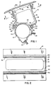
- One end plate 19, as shown in Fig. 1 is suitably installed on the canister 12 prior to installation thereon of the passenger side cover 18.
- the other end plate (not shown) is attached to the canister 12 following the installation thereon of the cover 18.
- a plurality of screw retaining grooves are provided at each end of the canister 12 for retaining thereat a respectively associated end plate.
- Cover 18 may be made of any material suitable for serving a decorative function on the instrument panel of the automotive vehicle in which the module 10 is installed or for serving a non-decorative function therein as well as providing protection for the folded air bag 16. As shown in Figs. 1, 3 and 4, the cover 18 may be slightly curved to match the profile of the vehicle instrument panel and has no projecting flanges at the boundary line or perimeter thereof.
- Integrally formed with the canister 12 of the module 10 is an elongated continuous circumference one piece diffuser tube 20.
- Axially spaced inflating gas exit ports or slots 22 are provided in the portion of the wall of the diffuser tube 20.
- the inflator 14 Positioned within the diffuser tube 20 is the inflator 14.
- Brackets 24 and 26 are attached to the exterior of the module 10 for facilitating the installation of the module 10 in the instrument panel of an automotive vehicle.
- a passenger side cover 18 that matches the profile and decoration of the surface of the vehicle instrument panel may be provided. When the module 10 is installed in the vehicle, the decorative cover 18 forms part of the surface of the automotive instrument panel.
- the canister 12 includes an integrally formed top panel 28 and a bottom panel 30. That is to say, the top panel 28, the bottom panel 30, and the diffuser tube 20 are all made in one piece. If desired, however, the diffuser 20, the top panel 28 and the bottom panel need not be made in a single piece.
- the top panel 28 and bottom panel 30 in conjunction with the diffuser tube 20 and an end plate at each of the opposite ends of the canister 12 define a cavity 32. Cavity 32 is formed within a housing 33 of the canister 12. Housing 33 has a perimeter 35 at the air bag deployment end thereof. The air bag folded in a conventional manner and forming the air bag 16 is housed in cavity 32.
- Fig. 1 shows a cross sectional view of the continuous circumference one piece diffuser tube 20 with the integrally formed top panel 28 and bottom panel 30 of the canister 12.
- the diffuser 20 and top panel 28 and the bottom panel 30, as previously mentioned, are formed in a single piece as a continuous or unitary structure.
- the configuration of the diffuser tube 20 and the canister housing 33 can be produced in extruded aluminum or steel.
- the slots 22 in the diffuser portion of the diffuser tube 20, that portion which faces the air bag cushion envelope 16, that is, the gas inlet opening thereof, are located and sized so as to provide a desired distribution of gas into the air bag 16 of inflating gas that is produced by the inflator 14.
- the inflator 14 has an elongated cylindrical configuration and is retained in the diffuser tube 20, in concentric relation therewith, between the two opposed end plates.
- a pair of elongated key hole shaped slots or grooves 34 and 36 which are provided at the inflating gas inlet side of the cavity 32 in association, respectively, with the top panel 28 and the bottom panel 30.
- the fabric of the air bag 16 is formed and sewn into a loop, specifically a loop 38 at the upper side and a loop 40 at the lower side.
- the loops 38 and 40 are inserted in respectively associated grooves 42 and 44 that are formed at the forward ends of the upper and lower panels 28 and 30 adjacent the diffuser tube 20.
- Squeezing of the loops 38 and 40 is required to facilitate such insertion through a respective narrow entry way 43 and 45 provided into each of the respectively associated grooves 42 and 44.
- Retention of the loops 38 and 40 in the grooves 42 and 44 and thereby attachment of the air bag 16 to the canister 12 and the diffuser tube 20 is effected by the insertion of rods 46 and 48 through the loops 38 and 40, respectively, and thereby through the respectively associated grooves 42 and 44.
- the rods 46 and 48 may be fastened securely in fully inserted position in any suitable manner.
- the cover 18 is attached to the module 10 by a slide/track attachment device comprising a track or groove formed at the perimeter 35 of the canister 12, that is, the upper ends of each of the upper panel 28 and of the lower panel 30 remote from the diffuser tube 20. More specifically, a straight track 50 is formed at the upper end of the upper panel 28 along the length thereof and a straight track 52 is formed at the upper end of the lower panel 30 along the length thereof.
- Each of the tracks 50 and 52 comprise part of the canister perimeter 35 and is formed as a straight elongated key hole slot or groove that extends for the full length of the respectively associated upper panel 28 and lower panel 30.
- the cover 18 for the module 10 includes a feature, specifically straight elongated slides 54 and 56, which hang down or depend on depending portions 58 and 60 from the under side of the cover 18. Slides 54 and 56 are so positioned as to be slideable into a respectively associated one of the elongated tracks 50 and 52 of the canister 12. Thus, as shown in Figs. 1 and 3, the slide 54 is formed on the end of an elongated depending portion 58 that extends or hangs downwardly for substantially the entire length of the cover 18. The downwardly extending distance of the portions 58 and 60 is such that with the cover installed on module 10 and the module 10 installed in the automotive vehicle and secured thereto by the brackets 24 and 26, the cover 18 will then close the opening in the instrument panel of the vehicle in substantially flush relation.
- the cover 18 must be installed on the module 10 before the module 10 is installed in the vehicle. Additionally, for the cover 18 to be installed on the module 10, the installation of the end plate on one side at least of the module 10 must be postponed until the cover 18 has been installed on the module 10. That is to say, installation of the cover 18 on the module 10 requires the positioning of the slides 54 and 56 at one end thereof adjacent one end of the canister 12 so that the slides 54 and 56 may enter and slide into the respectively associated tracks 50 and 52. Sliding of the slides 54 and 56 for substantially the full length of the tracks 50 and 52 is necessary for proper installation of the cover 18 on the canister 12. When the cover 18 has been installed on the module 10, the installation of the second end plate on the canister 12 is carried out.
- the inflator 14 is activated and inflation gases pass through the gas exit slots 22 in the diffuser tube 20 into a gas inlet opening (not shown) in the folded air bag 16. The resulting pressure forces open the cover 18 causing it to rupture along a break seam 18a. After the cover 18 has thus been ruptured and forced open, the inflatable air bag 16 is deployed.
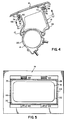
- Fig. 4 there is illustrated a second embodiment of the invention comprising an attach feature for an air bag restraint passenger module to secure a decorative or a non-decorative cover to a module or canister.
- the canister in Fig. 4 could be made of extruded aluminum or steel.
- the air bag restraint system shown in Fig. 4 and designated 10' includes an elongated canister 20, an elongated inflator 14, a folded air bag or cushion envelope 16, a top panel 28 and a bottom panel 30. These components may be substantially like the correspondingly numbered components shown in Figs. 1-3 and described in connection with the first embodiment of the invention.
- the attach feature consists of several clips 62 around the perimeter 35 defined by the ends of the upper panel 28 and the lower panel 30 and by two opposed end plates 64 and 66.
- the two end plates 64 and 66 are attached to the opposed ends of the canister 12 before the cover 18 is attached thereto.
- the arrangement is such that the clips 62 interface with or engage with openings, grooves, or cutouts 70 in a rectangularly shaped depending portion 68 that is slightly larger than that of the perimeter 35 of the canister housing 33.
- the depending portion 68 hangs down from the cover 18.
- Each of the clips 62 on the upper edge of the panels 28 and 30 and of the end plates 64 and 66 on which, optionally, they may also be provided, that is, on the upper edge of the module housing 72, are curved outwardly forming a rolled over lip 74.
- Each lip 74 engages and is locked in mating relation in the grooves in the inner side 76 of depending portion 68 when the module housing 72 and the folded air bag cushion 16 are pressed in place with the depending portion 68 that is attached to the lower side of the cover 18.
- the clips 62 are suitably formed in the upper portions of the module housing 72, that is, of the upper portions of the top panel 28 and the bottom panel 30.
- each of the clips may comprise a separate component that is attached in a suitable manner to the upper edge of the module housing 72.
- a cover 18 with this attach feature would be installed vertically and would be snapped into place. This feature would eliminate all fasteners associated with attaching a cover to a passenger air bag module.
Landscapes
- Engineering & Computer Science (AREA)
- Mechanical Engineering (AREA)
- Air Bags (AREA)
Applications Claiming Priority (2)
| Application Number | Priority Date | Filing Date | Title |
|---|---|---|---|
| US310551 | 1981-10-13 | ||
| US31055194A | 1994-09-22 | 1994-09-22 |
Publications (1)
| Publication Number | Publication Date |
|---|---|
| EP0703122A1 true EP0703122A1 (de) | 1996-03-27 |
Family
ID=23203023
Family Applications (1)
| Application Number | Title | Priority Date | Filing Date |
|---|---|---|---|
| EP95306315A Withdrawn EP0703122A1 (de) | 1994-09-22 | 1995-09-08 | Vorrichtung und Verfahren zum Befestigen eines Luftsackmoduldeckels auf der Beifahrerseite |
Country Status (2)
| Country | Link |
|---|---|
| EP (1) | EP0703122A1 (de) |
| JP (1) | JP3022511U (de) |
Cited By (5)
| Publication number | Priority date | Publication date | Assignee | Title |
|---|---|---|---|---|
| EP0747269A1 (de) * | 1995-06-08 | 1996-12-11 | Morton International, Inc. | Integrierte Befestigung eines Beifahrer-Luftsackmoduldeckels |
| US6325407B1 (en) | 1999-10-18 | 2001-12-04 | Autoliv Asp, Inc. | Airbag module cover attachment |
| DE102008017636A1 (de) * | 2008-04-04 | 2010-01-14 | Autoliv Development Ab | Gassackmodul |
| FR3085324A1 (fr) | 2018-08-29 | 2020-03-06 | Faurecia Interieur Industrie | Dispositif de reception d'un sac gonflable de securite a double systeme de retenue, element de garnissage et vehicule associes |
| CN118996732A (zh) * | 2024-08-19 | 2024-11-22 | 胤勤自动化科技(广东)有限公司 | 气袋自动扣包布设备 |
Families Citing this family (1)
| Publication number | Priority date | Publication date | Assignee | Title |
|---|---|---|---|---|
| JPH0832992B2 (ja) * | 1992-07-14 | 1996-03-29 | 典親 近藤 | 形状記憶合金を利用する絞り製品の製造法 |
Citations (9)
| Publication number | Priority date | Publication date | Assignee | Title |
|---|---|---|---|---|
| US4941678A (en) * | 1989-06-29 | 1990-07-17 | Morton Thiokol, Inc. | Lightweight reaction can for passenger inflators |
| DE9110293U1 (de) * | 1991-08-20 | 1991-09-26 | TRW Repa GmbH, 7077 Alfdorf | Gassack-Rückhaltesystem-Baugruppe |
| US5135252A (en) * | 1991-07-15 | 1992-08-04 | Chrysler Corporation | Mounting means for a vehicle passenger side air bag structure |
| JPH05648A (ja) * | 1991-03-29 | 1993-01-08 | Mazda Motor Corp | 自動車のエアバツグ装置 |
| EP0558240A1 (de) * | 1992-02-24 | 1993-09-01 | Morton International, Inc. | Reaktionsdose mit kreisförmigem Diffusor |
| EP0602785A2 (de) * | 1992-12-18 | 1994-06-22 | Morton International, Inc. | Diffusorvorrichtung und deren Einbau in ein aufblasbares Rückhaltesystem |
| US5338060A (en) * | 1993-06-18 | 1994-08-16 | Morton International, Inc. | Energy dissipation features in air bag closures |
| WO1994025313A1 (en) * | 1993-04-30 | 1994-11-10 | Alliedsignal Inc. | Air bag module with extruded housing |
| US5439246A (en) * | 1994-02-07 | 1995-08-08 | Morton Internatinal, Inc. | Multi-directional air bag module door attachment |
-
1995
- 1995-09-08 EP EP95306315A patent/EP0703122A1/de not_active Withdrawn
- 1995-09-08 JP JP1995009548U patent/JP3022511U/ja not_active Expired - Lifetime
Patent Citations (9)
| Publication number | Priority date | Publication date | Assignee | Title |
|---|---|---|---|---|
| US4941678A (en) * | 1989-06-29 | 1990-07-17 | Morton Thiokol, Inc. | Lightweight reaction can for passenger inflators |
| JPH05648A (ja) * | 1991-03-29 | 1993-01-08 | Mazda Motor Corp | 自動車のエアバツグ装置 |
| US5135252A (en) * | 1991-07-15 | 1992-08-04 | Chrysler Corporation | Mounting means for a vehicle passenger side air bag structure |
| DE9110293U1 (de) * | 1991-08-20 | 1991-09-26 | TRW Repa GmbH, 7077 Alfdorf | Gassack-Rückhaltesystem-Baugruppe |
| EP0558240A1 (de) * | 1992-02-24 | 1993-09-01 | Morton International, Inc. | Reaktionsdose mit kreisförmigem Diffusor |
| EP0602785A2 (de) * | 1992-12-18 | 1994-06-22 | Morton International, Inc. | Diffusorvorrichtung und deren Einbau in ein aufblasbares Rückhaltesystem |
| WO1994025313A1 (en) * | 1993-04-30 | 1994-11-10 | Alliedsignal Inc. | Air bag module with extruded housing |
| US5338060A (en) * | 1993-06-18 | 1994-08-16 | Morton International, Inc. | Energy dissipation features in air bag closures |
| US5439246A (en) * | 1994-02-07 | 1995-08-08 | Morton Internatinal, Inc. | Multi-directional air bag module door attachment |
Non-Patent Citations (1)
| Title |
|---|
| PATENT ABSTRACTS OF JAPAN vol. 017, no. 260 (M - 1414) 21 May 1993 (1993-05-21) * |
Cited By (6)
| Publication number | Priority date | Publication date | Assignee | Title |
|---|---|---|---|---|
| EP0747269A1 (de) * | 1995-06-08 | 1996-12-11 | Morton International, Inc. | Integrierte Befestigung eines Beifahrer-Luftsackmoduldeckels |
| US6325407B1 (en) | 1999-10-18 | 2001-12-04 | Autoliv Asp, Inc. | Airbag module cover attachment |
| DE102008017636A1 (de) * | 2008-04-04 | 2010-01-14 | Autoliv Development Ab | Gassackmodul |
| DE102008017636B4 (de) * | 2008-04-04 | 2010-04-01 | Autoliv Development Ab | Gassackmodul |
| FR3085324A1 (fr) | 2018-08-29 | 2020-03-06 | Faurecia Interieur Industrie | Dispositif de reception d'un sac gonflable de securite a double systeme de retenue, element de garnissage et vehicule associes |
| CN118996732A (zh) * | 2024-08-19 | 2024-11-22 | 胤勤自动化科技(广东)有限公司 | 气袋自动扣包布设备 |
Also Published As
| Publication number | Publication date |
|---|---|
| JP3022511U (ja) | 1996-03-26 |
Similar Documents
| Publication | Publication Date | Title |
|---|---|---|
| US20050046154A1 (en) | Inflatable curtain mounting bracket | |
| EP1201509B1 (de) | Überrollschutzvorhang für ein Kraftfahrzeug | |
| CA2108325C (en) | Air bag retention in inflatable restraint systems | |
| US5647607A (en) | Tether attachment apparatus for air bag cover | |
| US7677593B2 (en) | Side airbag curtain directional deployment bracket | |
| US7673897B2 (en) | Head-protecting airbag apparatus | |
| US5564732A (en) | Adjustable deployment door for airbag module | |
| US20010026063A1 (en) | Air bag device for passenger's seat | |
| KR19980703305A (ko) | 에어 백 모듈 | |
| JP3045705U (ja) | モジュールカバー及びモジュールハウジング並びにエアバッグモジュール | |
| US5979929A (en) | Fastenerless slip-on spring clip for airbag module retention | |
| US7100939B2 (en) | Inflatable curtain assembly | |
| EP0663325B1 (de) | Beifahrer-Luftsackmodul mit langgestrecktem Reaktionsgehäuse | |
| US20080122203A1 (en) | Airbag assembly | |
| JP3016637U (ja) | 自動車のダッシュボード基枠上に設置されるエアバッグインフレータのサブアセンブリ | |
| EP0680852A2 (de) | Bandverankerte, befestigungsmittelfreie Entfaltungsklappe für Insassen-Seiten-Airbagmodul | |
| US7320477B2 (en) | Air bag system | |
| US5765862A (en) | Fastening system for air bag deployment doors | |
| JP3013530B2 (ja) | サイドエアバッグの取付構造 | |
| US5876058A (en) | Air bag module | |
| DE19750945A1 (de) | Seitenaufprallschutzmodul zur Montage an einem Sitz eines Kraftfahrzeugs | |
| US5480183A (en) | Airbag cover retainer | |
| US20090079172A1 (en) | Curtain airbag module | |
| WO1994025313A1 (en) | Air bag module with extruded housing | |
| JP2003072508A (ja) | エアバック装置 |
Legal Events
| Date | Code | Title | Description |
|---|---|---|---|
| PUAI | Public reference made under article 153(3) epc to a published international application that has entered the european phase |
Free format text: ORIGINAL CODE: 0009012 |
|
| AK | Designated contracting states |
Kind code of ref document: A1 Designated state(s): DE FR GB IT |
|
| STAA | Information on the status of an ep patent application or granted ep patent |
Free format text: STATUS: THE APPLICATION IS DEEMED TO BE WITHDRAWN |
|
| 18D | Application deemed to be withdrawn |
Effective date: 19960928 |