EP0703328A1 - Enduit de base pour le plâtre - Google Patents
Enduit de base pour le plâtre Download PDFInfo
- Publication number
- EP0703328A1 EP0703328A1 EP95114769A EP95114769A EP0703328A1 EP 0703328 A1 EP0703328 A1 EP 0703328A1 EP 95114769 A EP95114769 A EP 95114769A EP 95114769 A EP95114769 A EP 95114769A EP 0703328 A1 EP0703328 A1 EP 0703328A1
- Authority
- EP
- European Patent Office
- Prior art keywords
- spacers
- plaster
- base plate
- spacer
- slot
- Prior art date
- Legal status (The legal status is an assumption and is not a legal conclusion. Google has not performed a legal analysis and makes no representation as to the accuracy of the status listed.)
- Granted
Links
- 239000011505 plaster Substances 0.000 title claims abstract description 66
- 239000000853 adhesive Substances 0.000 claims abstract description 18
- 230000001070 adhesive effect Effects 0.000 claims abstract description 18
- 239000000463 material Substances 0.000 claims abstract description 16
- 239000004033 plastic Substances 0.000 claims abstract description 4
- 229920003023 plastic Polymers 0.000 claims abstract description 4
- 125000006850 spacer group Chemical group 0.000 claims description 121
- 238000004140 cleaning Methods 0.000 claims description 28
- 238000004519 manufacturing process Methods 0.000 claims description 17
- 238000000034 method Methods 0.000 claims description 7
- 238000003825 pressing Methods 0.000 claims description 7
- 238000005452 bending Methods 0.000 claims description 6
- 239000003365 glass fiber Substances 0.000 claims description 5
- 238000010924 continuous production Methods 0.000 claims description 2
- 239000004744 fabric Substances 0.000 claims 1
- 238000007493 shaping process Methods 0.000 claims 1
- 238000005253 cladding Methods 0.000 description 3
- 238000010276 construction Methods 0.000 description 3
- 239000002184 metal Substances 0.000 description 3
- 239000004570 mortar (masonry) Substances 0.000 description 3
- PPBRXRYQALVLMV-UHFFFAOYSA-N Styrene Chemical compound C=CC1=CC=CC=C1 PPBRXRYQALVLMV-UHFFFAOYSA-N 0.000 description 2
- 238000004026 adhesive bonding Methods 0.000 description 2
- 238000004873 anchoring Methods 0.000 description 2
- 239000011324 bead Substances 0.000 description 2
- 238000005520 cutting process Methods 0.000 description 2
- 230000002349 favourable effect Effects 0.000 description 2
- 239000002657 fibrous material Substances 0.000 description 2
- 239000006260 foam Substances 0.000 description 2
- 239000003292 glue Substances 0.000 description 2
- 238000003780 insertion Methods 0.000 description 2
- 230000037431 insertion Effects 0.000 description 2
- 238000009413 insulation Methods 0.000 description 2
- 230000035515 penetration Effects 0.000 description 2
- 239000002984 plastic foam Substances 0.000 description 2
- 230000002787 reinforcement Effects 0.000 description 2
- 239000000758 substrate Substances 0.000 description 2
- 239000004925 Acrylic resin Substances 0.000 description 1
- 229920000178 Acrylic resin Polymers 0.000 description 1
- 235000001674 Agaricus brunnescens Nutrition 0.000 description 1
- 230000015572 biosynthetic process Effects 0.000 description 1
- 239000013013 elastic material Substances 0.000 description 1
- 230000007613 environmental effect Effects 0.000 description 1
- 239000011152 fibreglass Substances 0.000 description 1
- 239000011521 glass Substances 0.000 description 1
- 239000011810 insulating material Substances 0.000 description 1
- 238000012986 modification Methods 0.000 description 1
- 230000004048 modification Effects 0.000 description 1
- 230000003014 reinforcing effect Effects 0.000 description 1
- 230000000087 stabilizing effect Effects 0.000 description 1
Images


Classifications
-
- E—FIXED CONSTRUCTIONS
- E04—BUILDING
- E04F—FINISHING WORK ON BUILDINGS, e.g. STAIRS, FLOORS
- E04F13/00—Coverings or linings, e.g. for walls or ceilings
- E04F13/02—Coverings or linings, e.g. for walls or ceilings of plastic materials hardening after applying, e.g. plaster
- E04F13/04—Bases for plaster
- E04F13/045—Means for fastening plaster-bases to a supporting structure
Definitions
- the invention relates to a plaster base with the features in the preamble of the main claim.
- Such a plaster base is known as a so-called building board from DE-A 31 23 636. It consists of a base plate with a caterpillar-shaped spacer, which keeps a cleaning grid at a distance from the base plate.
- the plaster grid serves to stabilize and reinforce the plaster.
- the spacer is applied as a meandering or straight bead from a plastic foam to the surface of the board. The foam sticks to both the plate and the grille. Due to stricter environmental protection conditions, there are problems for the further use of a plastic foam.
- a similar plaster base is known from DE-A-19 42 352. It consists of a base plate, several spacers in the form of adhesive mortar beads and a cleaning grid.
- the plaster grille is made of expanded metal and has triangular ribs that point downwards and hover in grooves on the top of the plate. The ribs serve to better anchor the plaster. The plaster can penetrate through the rib walls and cling to the dovetail grooves.
- US-A-1 110 309 shows a stucco carrier which consists of several spacer strips which are U-shaped in cross section and a stucco grille. The parts are delivered individually and assembled to a stucco beam at the construction site. The spacer strips are placed on the building base and fixed with hammered nails. The nails also hold stucco grids loosely placed on the spacers.
- a non-generic outer wall cladding is known, in which, at a distance from the masonry, a facing wall is formed by a large number of individual dowels, a plastering grid and a plaster layer and is then backfilled with an insulating material.
- the dowels have a widening on the head and also serve as spacers. The dowels are fixed in the masonry and penetrate the insulation layer.
- GB-A-2 124 293 also shows a similar outer wall cladding.
- the dowels penetrate the insulating layer and are anchored in the masonry.
- the outer wall cladding is only created at the construction site and is made up of several individual parts. It is not a prefabricated plaster base, in which the spacers, base plate and plaster grille are connected from the start to form a single unit.
- a mortar reinforcement that is also of a different type is known from DE-A 38 15 299. It consists of several loose spring clips, which are inserted into drill holes in the masonry and are intended to hold the mortar applied afterwards. With this reinforcement, which is created at the construction site, there is neither a plaster grille nor a base plate, nor are there any spacers.
- the invention solves this problem with the features in the main claim.
- the spacers Due to the recessed arrangement in the base plate, the spacers have a particularly good hold and an exact position fixation.
- the height of the spacers can also be varied and precisely adjusted.
- the spacers can be designed as towering thin-walled webs and still have a high stability.
- the thin walls are favorable for the cohesion of the plaster. Interruptions in the web wall and, in particular, a lattice-shaped design of the spacers, which enable the plaster to penetrate and effectively prevent stress cracks, are particularly advantageous here.
- the webs of the spacers can be straight or bow-shaped in cross section.
- the straight webs have an essentially smooth upper edge as a support surface for the cleaning grid.
- the bow shape offers an even wider support over the crossbar. There are various design options for the bow shape.
- a free space is created under the cross bar or the top edge of the web on which the plaster grid rests, into which the plaster can penetrate.
- the bracket shape creates a large support surface for the cleaning grid and still takes up little space for the plaster.
- the spacer can be made of any suitable and environmentally friendly material. It can be in the form of long strips that extend over most or the entire length of the base plate. But he can also have a smaller appearance, which means that there is free space for plaster penetration in all directions between the individual spacers.
- the spacer is preferably inserted in preformed slots in the base plate and processed and held there in a suitable manner. To open the slots and to facilitate the insertion of the spacers, it is advantageous to bend or bend the base plate slightly. It is also advisable to insert an additional adhesive into the slot.
- the spacer can be arranged on the base plate with a precisely determinable free space or cleaning grid height.
- the plaster base is therefore suitable for any type of plaster and plaster thickness and can be precisely adapted for the respective plaster. It is particularly suitable for so-called thin plasters with low plaster heights. The exact setting of the clearance or plaster grid height is facilitated by the slot formation, especially if the slot is made with the appropriate depth. There are other options for fixing the height.
- a preferably strip-shaped spacer can also be present between the crosspiece of the spacer and the base plate, onto which the spacer is pressed with a correspondingly suitable pressing device during the setting phase of the adhesive.
- the spacer positioned exactly in this way can then be glued to the surface and provided with the cleaning grid.
- the cleaning grid can be glued in strips from below and possibly also connected to the spacers in advance.
- the base plate is preferably connected to the spacers and the cleaning grid to form a structural unit.
- the structural unit can consist of the base plate and the spacers, the plaster grille being applied subsequently.
- the plaster base is preferably designed as a finished building board, which can be fastened to the substrate with suitable fastening elements, e.g. a masonry that is anchored. It can also be a component that is used in other areas, e.g. for roller shutter boxes.
- the plaster base (1) shown in the drawings consists of a base plate (2) on which one or more spacers (4) are arranged, which support, hold and hold a cleaning grid (3) and distance them from the surface of the base plate (2).
- the parts are connected to one another to form a prefabricated plaster base in the form of a building board or the like.
- a plaster layer (24) is applied to the plaster base (1), which is shown broken off in the left half of the figure in FIG. 1.
- the cleaning grid (3) and the spacers (4) are enclosed by the plaster layer.
- the plaster grille (3) serves as a support and for stabilizing and reinforcing the plaster. It is preferably arranged approximately at a 2/3 height of the plaster layer (24).
- the base plate (2) consists of a suitable material, for example a fiber material, a styrene foam or the like, which offers sufficient rigidity for the plate shape, but on the other hand is also not too firm and can be shaped.
- the base plate (2) is fastened to the substrate, in particular a wall or masonry, by means of dowels or in another suitable manner.
- the cleaning grid (3) consists of plastic, metal or another suitable material, for example a glass fiber material or the like. It can be braided, woven, or made in some other way.
- the spacers (4) are arranged and held in the base plate (2) at least to a certain extent. This arrangement offers a preferably form-fitting, fixed fixation and stable longitudinal and lateral guidance for the spacers (4).
- the individual spacers (4) are preferably designed as high ridges and have a thin wall thickness in the millimeter range. In cross section they can be designed as straight webs according to FIG. 5. These have a substantially smooth and straight upper edge (28) on which the cleaning grid (3) rests at a distance or free space (8) above the surface of the plate.
- the spacers (4) according to FIGS. 1 and 2 can have an angled bow shape in cross section. They have at least one transverse web (5) which extends to form a free space (8) at a distance above the base plate (2).
- the bow shape is essentially U-shaped. Alternatively, it can also be L-shaped or T-shaped.
- the spacers (4) or webs are arranged in all embodiments with one or more feet (6) in the base plate (2) recessed a bit or embedded and held.
- the transverse webs (5) or web top edges (28) are preferably aligned straight and parallel to the surface of the base plate (2). Alternatively, they can also be bent or deformed in some other way.
- the plaster grid (3) lying on top is fixed by an adhesive or another suitable connection, e.g. a seam, held tight.
- the one or more feet (6) are preferably aligned perpendicular to the base plate (2).
- the spacers (4) preferably have the shape of elongated strips which extend over the entire length and / or width of the base plate (2). However, they can also be significantly shorter and be arranged at a distance from one another to form gaps.
- the spacers (4) preferably run straight and parallel to one another. They are evenly distributed on the base plate (2).
- the spacers (4) can also be designed in a star or mushroom shape, as circular pots or in any other way.
- the spacers (4) can be made of any suitable materials. In the preferred embodiment, they consist of a woven or braided grid.
- the lattice shape can also be formed by a perforated plate or other forms of interruptions or wall openings which allow the plaster (24) to reach through the web.
- the plaster (24) can penetrate into the inner free space (8) under the crosspiece (s) (5).
- the end faces are open and also allow the plaster (24) to enter.
- Prepared slots (7) are preferably arranged in the base plate (2) to accommodate the spacer feet (6).
- the slot depth can be adapted to the desired height of the spacers (4) or the free space (8) or the cleaning grid (3) above the base plate (2).
- the spacers (4) preferably have a smooth edge at the lower edge of the feet (6) and are flat on the bottom of the slots (7). By changing the slot depth, the spacer height can be varied and set to the desired size.
- the slots (7) can be linear or point-shaped in plan view.
- the spacer height can also be determined and set in any other way.
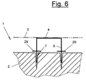
- Figure 6 shows e.g. an alternative with one or two transverse ribs (29), thickened portions or the like on the upper webs of the spacers (4).
- the transverse ribs (29) positioned at a predetermined height are supported on the upper side of the base plate and limit the depth of penetration of the feet (6) in the slot (7).
- the slot (7) can be without a support function and deeper than necessary.
- the slots (7) are narrow and can be adapted to the thickness of the spacers (4). If the base plate material is appropriately elastic, they tend to narrow or close. The feet (6) can thereby be held in the slots (7) by pure clamping and the inherent elasticity of the base plate material. In the drawings, the slots (7) are shown open for the sake of clarity. A lattice structure of the feet (6) in connection with a fiber material of the base plate (2) cause a certain matting and a form-fitting hold. For better anchoring, it is advisable to insert an adhesive into the slots (7) that connects the feet (6) to the slot walls.
- the spacers (4) can be made of a suitable material. In the preferred embodiment, they consist of a glass fiber material. Alternatively, other plastics, but also metal or the like, can be considered. In the straight web shape of Fig. 5, it is advisable to use the glass fiber material in a suitable manner, e.g. to be reinforced by an acrylic resin sheathing or the like.
- the spacers (4) and the cleaning grid (3) consist of the same glass grid material, as a result of which different tensions and possible cleaning cracks are avoided. This is also favorable for an optimal connection of the parts and for easier disposal.
- the base plate (2) is preferably transported continuously in the conveying direction (23) via a suitable conveyor device (27) on a roller conveyor or the like.
- the base plate (2) can already be cut to size, the individual plates being conveyed one behind the other and preferably abutting one another.
- the base plate (2) can initially also be in the form of a strand and can only be cut to the desired size at the end of the production device (9).
- the production device (9) initially has a slot station (10), which is followed by a spacer station and a grid station (20).
- the plaster base (1) in Continuous process manufactured. Alternatively, manufacturing can also be carried out in single steps and separate stations.
- the aforementioned slots (7) are introduced into the moving base plate (2).
- several slitting devices (11) are provided, which consist, for example, of standing but height-adjustable knives, rotating cutting wheels or the like other suitable tools. Spacers (not shown) for the specific depth of the slot (7) are located on the slot knives.
- the slitting device (11) also has an opener (12) which widens the slit (7) for filling with the adhesive and keeps it open for at least a time.
- an opener (12) which widens the slit (7) for filling with the adhesive and keeps it open for at least a time.
- discs with cutters roll, which open the slits (7) for the adhesive flowing in behind them.
- the openers (12) can also be formed by conical extensions which widen upwards and in the conveying direction (23).
- a suitable filling device (13) for the adhesive is arranged behind each of the slot devices (11). These are, for example, nozzles, which are each positioned above the slots (7). Knives, disks and filling device form one unit.
- a bending device (not shown) which bends the base plate about the longitudinal axis or the slot axis. This can be done in the area of the adhesive device (13) and / or the spacer station (14). Due to the convex curvature, the slots on the top of the panel open and facilitate the introduction of the adhesive and / or the spacers (4).
- the spacer station (14) has a feed device (15) for the spacers (4).
- the spacers can be prefabricated. In the simple embodiment with straight webs, the spacers (4) are in the form of pre-cut strips.
- bow-shaped spacers (4) are used. They preferably receive their bow shape only in the spacer station (14).
- a suitable bending device (16) is provided, which bends the essentially flat grid mat (25) supplied at the beginning to the desired bow shape.
- the preferred spacer (4) made of fiberglass mesh it is advisable to overbend the feet (6) and to overstretch or break the bending edges.
- the bent or the straight spacer (4) is then fed to the base plate (2) via a form holder (17).
- the form holder (17) forms a form-fitting guide for the spacer (4) and stabilizes its shape. It is aligned with the base plate (2) in such a way that the spacer (4) with its feet (6) slides precisely into the prefabricated slots (7). If the spacer (4) consists of an elastic material, the feet (6) can spread out again somewhat in the slots (7) after exiting the mold holder (17), which improves the anchoring.
- the spacer station (14) can have a spacer (19) with a pressing device (18) for each spacer (4).
- the spacers (19) consist of spacer strips (19) which extend along the slots (7) and at the rear end a transverse bridge (26) are attached.
- the spacers (19) lie loosely on the base plate (2) which slides under them.
- the spacers (4) are guided by the feed device (15) over the spacers (19), which thereby determine the insertion depth in the base plate (2) and the clearance height.
- the following pressure device (18) consists, for example, of several freely rotatable and height-adjustable pressure rollers which press the spacers (4) onto the spacers (19). Alternatively, it can also be pressure rails or other suitable devices.
- the length of the spacers (19) and the extent of the pressing device (18) are chosen so that at the end the adhesive has produced a sufficiently strong connection between the diaphragm walls and the feet (6).
- the grid station (20) follows. It has a glue device (21) which applies a suitable adhesive to the cleaning grid (3) and / or the crossbars (5) of the spacers (4). The application can be done in the form of strips of glue or the like.
- a grid guide (22) is also provided, through which the cleaning grid (3) is fed and placed on the spacers (4). Possibly. suitable pressing devices (not shown) can follow.
- the grid station (20) can also have another suitable device for connecting the cleaning grid (3) to the spacers (4).
- the spacers (4) can first be connected to the cleaning grid (3), in particular glued or sewn. Spacers (4) and cleaning grille (3) are then jointly fed to the base plate (2) and used.
- the spacers (19) then interact with the cleaning grille (3).
- the individual process steps can also be carried out manually and separately in succession.
- Individual components for example the bending device (16), the pressing device (18), the spacers (19) etc. can also be omitted.
- base plates with prefabricated slots where, for example, the slots have already been formed in the plate production. The slot station is then also unnecessary.
- the spacers (4) can also be pressed into a correspondingly soft base plate without prepared slots if the shape is sufficient.
Landscapes
- Engineering & Computer Science (AREA)
- Architecture (AREA)
- Civil Engineering (AREA)
- Structural Engineering (AREA)
- Laminated Bodies (AREA)
- Finishing Walls (AREA)
- Building Environments (AREA)
Applications Claiming Priority (4)
| Application Number | Priority Date | Filing Date | Title |
|---|---|---|---|
| DE4434023A DE4434023C2 (de) | 1994-09-23 | 1994-09-23 | Putzträger |
| DE4434023 | 1994-09-23 | ||
| DE29504247U DE29504247U1 (de) | 1994-09-23 | 1995-03-11 | Putzträger |
| DE29504247U | 1995-03-11 |
Publications (2)
| Publication Number | Publication Date |
|---|---|
| EP0703328A1 true EP0703328A1 (fr) | 1996-03-27 |
| EP0703328B1 EP0703328B1 (fr) | 1999-03-31 |
Family
ID=25940416
Family Applications (1)
| Application Number | Title | Priority Date | Filing Date |
|---|---|---|---|
| EP95114769A Expired - Lifetime EP0703328B1 (fr) | 1994-09-23 | 1995-09-20 | Enduit de base pour le plâtre |
Country Status (2)
| Country | Link |
|---|---|
| EP (1) | EP0703328B1 (fr) |
| AT (1) | ATE178381T1 (fr) |
Cited By (2)
| Publication number | Priority date | Publication date | Assignee | Title |
|---|---|---|---|---|
| RU2147656C1 (ru) * | 1998-11-30 | 2000-04-20 | Ситников Иван Васильевич | Облицовка зданий, сооружений, конструкций |
| RU2329360C2 (ru) * | 2006-09-25 | 2008-07-20 | Юрий Владимирович Новиков | Декоративный стеновой строительный блок |
Citations (11)
| Publication number | Priority date | Publication date | Assignee | Title |
|---|---|---|---|---|
| US1110309A (en) | 1914-09-15 | Joseph Bristow Jr | Stucco construction. | |
| DE1942352A1 (de) | 1969-08-20 | 1971-03-04 | Buchmann Rudolf Ch | Bauelement aus expandiertem Kunststoff mit Putztraeger aus Streckblech und Verfahren zu seiner Herstellung |
| EP0011781A1 (fr) * | 1978-11-24 | 1980-06-11 | Friedrich Heck | Procédé pour la fabrication de façades enduites et isolantes et plaques isolantes pour la mise en oeuvre de ce procédé |
| DE3123636A1 (de) | 1980-07-02 | 1982-03-18 | Alfred 8919 Schondorf Wiehofsky | Bauplatte |
| EP0056640A2 (fr) * | 1979-12-17 | 1982-07-28 | BASF Aktiengesellschaft | Panneaux isolants thermiques pour le montage entre les chevrons |
| GB2124293A (en) | 1982-07-27 | 1984-02-15 | Itw Ltd | Fasteners for wire mesh |
| AT374534B (de) | 1981-12-23 | 1984-05-10 | Staussziegel Ind Ges M B H | Verfahren zur herstellung einer waermedaemmenden bauwerksaussenwandverkleidung |
| DE3114732C2 (fr) | 1981-04-11 | 1987-07-30 | Eugen 7101 Abstatt De Traub | |
| CH669628A5 (en) * | 1985-06-20 | 1989-03-31 | Werner G Sieger | Insulated and ventilated wall covering layer - uses wire grid structure on insulating layer to form air gap behind cladding layer |
| DE3815299A1 (de) | 1988-05-05 | 1989-11-16 | Stauch Matthias | Vorrichtung und verfahren zur armierung von moertel |
| DE9006889U1 (de) | 1990-06-15 | 1990-08-30 | Montenovo-Werke Hans Heitmann KG, 5950 Finnentrop | Wärmedämm-Platte |
-
1995
- 1995-09-20 EP EP95114769A patent/EP0703328B1/fr not_active Expired - Lifetime
- 1995-09-20 AT AT95114769T patent/ATE178381T1/de not_active IP Right Cessation
Patent Citations (11)
| Publication number | Priority date | Publication date | Assignee | Title |
|---|---|---|---|---|
| US1110309A (en) | 1914-09-15 | Joseph Bristow Jr | Stucco construction. | |
| DE1942352A1 (de) | 1969-08-20 | 1971-03-04 | Buchmann Rudolf Ch | Bauelement aus expandiertem Kunststoff mit Putztraeger aus Streckblech und Verfahren zu seiner Herstellung |
| EP0011781A1 (fr) * | 1978-11-24 | 1980-06-11 | Friedrich Heck | Procédé pour la fabrication de façades enduites et isolantes et plaques isolantes pour la mise en oeuvre de ce procédé |
| EP0056640A2 (fr) * | 1979-12-17 | 1982-07-28 | BASF Aktiengesellschaft | Panneaux isolants thermiques pour le montage entre les chevrons |
| DE3123636A1 (de) | 1980-07-02 | 1982-03-18 | Alfred 8919 Schondorf Wiehofsky | Bauplatte |
| DE3114732C2 (fr) | 1981-04-11 | 1987-07-30 | Eugen 7101 Abstatt De Traub | |
| AT374534B (de) | 1981-12-23 | 1984-05-10 | Staussziegel Ind Ges M B H | Verfahren zur herstellung einer waermedaemmenden bauwerksaussenwandverkleidung |
| GB2124293A (en) | 1982-07-27 | 1984-02-15 | Itw Ltd | Fasteners for wire mesh |
| CH669628A5 (en) * | 1985-06-20 | 1989-03-31 | Werner G Sieger | Insulated and ventilated wall covering layer - uses wire grid structure on insulating layer to form air gap behind cladding layer |
| DE3815299A1 (de) | 1988-05-05 | 1989-11-16 | Stauch Matthias | Vorrichtung und verfahren zur armierung von moertel |
| DE9006889U1 (de) | 1990-06-15 | 1990-08-30 | Montenovo-Werke Hans Heitmann KG, 5950 Finnentrop | Wärmedämm-Platte |
Cited By (2)
| Publication number | Priority date | Publication date | Assignee | Title |
|---|---|---|---|---|
| RU2147656C1 (ru) * | 1998-11-30 | 2000-04-20 | Ситников Иван Васильевич | Облицовка зданий, сооружений, конструкций |
| RU2329360C2 (ru) * | 2006-09-25 | 2008-07-20 | Юрий Владимирович Новиков | Декоративный стеновой строительный блок |
Also Published As
| Publication number | Publication date |
|---|---|
| EP0703328B1 (fr) | 1999-03-31 |
| ATE178381T1 (de) | 1999-04-15 |
Similar Documents
| Publication | Publication Date | Title |
|---|---|---|
| EP1857606B1 (fr) | Structure d'isolation thermique à un mur de bâtiment avec une baguette pour plâtre | |
| EP0093697A2 (fr) | Procédé et dispositif de fabrication d'un élément profilé utilisé en tant que coffrage perdu | |
| EP0341507B1 (fr) | Coffrage | |
| EP1635971B1 (fr) | Installation pour fabriquer des elements de construction | |
| AT402084B (de) | Verlorenes schalungselement | |
| DE2620044C3 (de) | Dacheindeckungsbahn o.dgl. sowie Verfahren und Vorrichtung zum Herstellen derselben | |
| EP0703328A1 (fr) | Enduit de base pour le plâtre | |
| DE2849805A1 (de) | Bauelement fuer flaechenheizungen | |
| DE4135581A1 (de) | Bauplatte und verfahren zu ihrer herstellung | |
| DE4434023C2 (de) | Putzträger | |
| EP4063589B1 (fr) | Élément de coffrage pour une construction en béton, procede de production un tel coffrage et un procede de coffrage | |
| EP1395378B1 (fr) | Installation de production de composants en continu | |
| DE2658622A1 (de) | Schalungselement | |
| EP0789116B1 (fr) | Elément de coffrage | |
| DE2825552A1 (de) | Vorrichtung zum verlegen von platten, steinen o.dgl. | |
| EP0773333B1 (fr) | Armature pour maçonnerie | |
| EP0474239B1 (fr) | Support pour enduit et procédé pour sa fabrication | |
| DE3641747A1 (de) | Keramik-fassadenplatten, strangpressform zu deren herstellung und aus derartigen platten hergestellte fassaden | |
| DE2950614A1 (de) | Endlosprofil fuer die herstelung von stahlbetondecken, verfahren zur herstellung des profils und der decken | |
| DE102007053473A1 (de) | Metallelement | |
| EP2857605A1 (fr) | Élément de coffrage | |
| DE3047116A1 (de) | Abstandshalter fuer stahlbetonbewehrungen sowie verfahren zur herstellung solcher abstandshalter | |
| DE9306801U1 (de) | Bauplatte | |
| DE102011088446B4 (de) | Schalungselement und Verfahren zu dessen Herstellung | |
| DE20016262U1 (de) | Trägerplatte zum Anbringen von Klinkerriemchen od.dgl. |
Legal Events
| Date | Code | Title | Description |
|---|---|---|---|
| PUAI | Public reference made under article 153(3) epc to a published international application that has entered the european phase |
Free format text: ORIGINAL CODE: 0009012 |
|
| AK | Designated contracting states |
Kind code of ref document: A1 Designated state(s): AT CH DE FR LI |
|
| 17P | Request for examination filed |
Effective date: 19960802 |
|
| GRAG | Despatch of communication of intention to grant |
Free format text: ORIGINAL CODE: EPIDOS AGRA |
|
| 17Q | First examination report despatched |
Effective date: 19980619 |
|
| GRAG | Despatch of communication of intention to grant |
Free format text: ORIGINAL CODE: EPIDOS AGRA |
|
| GRAH | Despatch of communication of intention to grant a patent |
Free format text: ORIGINAL CODE: EPIDOS IGRA |
|
| GRAH | Despatch of communication of intention to grant a patent |
Free format text: ORIGINAL CODE: EPIDOS IGRA |
|
| GRAA | (expected) grant |
Free format text: ORIGINAL CODE: 0009210 |
|
| AK | Designated contracting states |
Kind code of ref document: B1 Designated state(s): AT CH DE FR LI |
|
| REF | Corresponds to: |
Ref document number: 178381 Country of ref document: AT Date of ref document: 19990415 Kind code of ref document: T |
|
| REG | Reference to a national code |
Ref country code: CH Ref legal event code: NV Representative=s name: E. BLUM & CO. PATENTANWAELTE Ref country code: CH Ref legal event code: EP |
|
| REF | Corresponds to: |
Ref document number: 59505490 Country of ref document: DE Date of ref document: 19990506 |
|
| ET | Fr: translation filed | ||
| RAP2 | Party data changed (patent owner data changed or rights of a patent transferred) |
Owner name: WIEHOFSKY, FRITZ |
|
| PG25 | Lapsed in a contracting state [announced via postgrant information from national office to epo] |
Ref country code: LI Free format text: LAPSE BECAUSE OF NON-PAYMENT OF DUE FEES Effective date: 19990930 Ref country code: CH Free format text: LAPSE BECAUSE OF NON-PAYMENT OF DUE FEES Effective date: 19990930 |
|
| PLBE | No opposition filed within time limit |
Free format text: ORIGINAL CODE: 0009261 |
|
| STAA | Information on the status of an ep patent application or granted ep patent |
Free format text: STATUS: NO OPPOSITION FILED WITHIN TIME LIMIT |
|
| 26N | No opposition filed | ||
| REG | Reference to a national code |
Ref country code: CH Ref legal event code: PL |
|
| PGFP | Annual fee paid to national office [announced via postgrant information from national office to epo] |
Ref country code: FR Payment date: 20020912 Year of fee payment: 8 |
|
| PGFP | Annual fee paid to national office [announced via postgrant information from national office to epo] |
Ref country code: DE Payment date: 20020920 Year of fee payment: 8 |
|
| PGFP | Annual fee paid to national office [announced via postgrant information from national office to epo] |
Ref country code: AT Payment date: 20020923 Year of fee payment: 8 |
|
| PG25 | Lapsed in a contracting state [announced via postgrant information from national office to epo] |
Ref country code: AT Free format text: LAPSE BECAUSE OF NON-PAYMENT OF DUE FEES Effective date: 20030920 |
|
| PG25 | Lapsed in a contracting state [announced via postgrant information from national office to epo] |
Ref country code: DE Free format text: LAPSE BECAUSE OF NON-PAYMENT OF DUE FEES Effective date: 20040401 |
|
| PG25 | Lapsed in a contracting state [announced via postgrant information from national office to epo] |
Ref country code: FR Free format text: LAPSE BECAUSE OF NON-PAYMENT OF DUE FEES Effective date: 20040528 |
|
| REG | Reference to a national code |
Ref country code: FR Ref legal event code: ST |