EP0703578B1 - Automatischer Plattenwechsler - Google Patents
Automatischer Plattenwechsler Download PDFInfo
- Publication number
- EP0703578B1 EP0703578B1 EP95114895A EP95114895A EP0703578B1 EP 0703578 B1 EP0703578 B1 EP 0703578B1 EP 95114895 A EP95114895 A EP 95114895A EP 95114895 A EP95114895 A EP 95114895A EP 0703578 B1 EP0703578 B1 EP 0703578B1
- Authority
- EP
- European Patent Office
- Prior art keywords
- disc
- light
- discs
- light reflectors
- display plate
- Prior art date
- Legal status (The legal status is an assumption and is not a legal conclusion. Google has not performed a legal analysis and makes no representation as to the accuracy of the status listed.)
- Expired - Lifetime
Links
- 238000012790 confirmation Methods 0.000 claims description 19
- 239000003086 colorant Substances 0.000 claims description 2
- 238000002372 labelling Methods 0.000 claims description 2
- 229920002972 Acrylic fiber Polymers 0.000 description 1
- 238000010276 construction Methods 0.000 description 1
- 230000000694 effects Effects 0.000 description 1
- 238000003780 insertion Methods 0.000 description 1
- 230000037431 insertion Effects 0.000 description 1
- 230000002452 interceptive effect Effects 0.000 description 1
- 239000012780 transparent material Substances 0.000 description 1
Images

Classifications
-
- G—PHYSICS
- G11—INFORMATION STORAGE
- G11B—INFORMATION STORAGE BASED ON RELATIVE MOVEMENT BETWEEN RECORD CARRIER AND TRANSDUCER
- G11B33/00—Constructional parts, details or accessories not provided for in the other groups of this subclass
- G11B33/10—Indicating arrangements; Warning arrangements
-
- G—PHYSICS
- G11—INFORMATION STORAGE
- G11B—INFORMATION STORAGE BASED ON RELATIVE MOVEMENT BETWEEN RECORD CARRIER AND TRANSDUCER
- G11B17/00—Guiding record carriers not specifically of filamentary or web form, or of supports therefor
- G11B17/22—Guiding record carriers not specifically of filamentary or web form, or of supports therefor from random access magazine of disc records
-
- G—PHYSICS
- G11—INFORMATION STORAGE
- G11B—INFORMATION STORAGE BASED ON RELATIVE MOVEMENT BETWEEN RECORD CARRIER AND TRANSDUCER
- G11B19/00—Driving, starting, stopping record carriers not specifically of filamentary or web form, or of supports therefor; Control thereof; Control of operating function ; Driving both disc and head
- G11B19/02—Control of operating function, e.g. switching from recording to reproducing
- G11B19/10—Control of operating function, e.g. switching from recording to reproducing by sensing presence or absence of record in accessible stored position or on turntable
Definitions
- the present invention relates to an auto disc changer, in particular to a disc confirmation apparatus for disc stocker which is suitable for an auto disc changer.
- an auto disc changer 910 currently in use which can store a number of discs 12 and can play back one of the discs 12 at a time, is shown in FIG. 9.
- Such an auto disc changer 910 has a disc stocker 913 in which a number of discs 12 can be stored at disc storage positions 913A, a carriage 914 which transfers a specified disc 12, a playback block (not shown) for playing back the specified disc 12, and a control block, in a cabinet 911.
- a transparent window 915 through which the user can see the stored discs 12 is formed into the front panel 911A of the cabinet 911.
- a tray 916 which loads and removes the discs 12 is positioned below the window 915.
- a display 917, which indicates the number representing the disc storage positions 913A in which the discs 12 are stored, and operation keys 918 are positioned at the right side of the transparent window 915.
- lines 919 indicating the positions of the discs 12 are printed beside the transparent window 915.
- a longer line is often used to indicate every set of ten discs 12. For example, if the user wishes to confirm that a disc 12 is stored in the 65th level from the bottom, it is easy to locate the 60th level using the longer lines 919 and then count up 5 lines. It is unnecessary to count 65 lines 919 from the bottom. Thus, the user can more easily confirm the position.
- a seal on which pointers 920 are printed may be used on the window 915.
- the pointers 920 are also much separated by a distance from the discs 12, it again may be difficult to determine which pointers 920 corresponds to which discs 12.
- the EP-A-0 267 547 discloses a storage means for compact discs comprising a transparent window for confirmation that a specific storage position is occupied. The indication is accomplished by mechanically actuated springs provided with an indicator part. Upon insertion of a disk in a storage position, the respective spring is moved and the indicator part obstructs the associated region in the window.
- the object of the present invention is to provide an auto disc changer with an improved disc confirmation apparatus for the disc stocker which allows the user to confirm where discs are stored.
- an auto disc changer with an improved disc confirmation apparatus which is characterized in first light reflectors formed into said transparent display plate, corresponding to a predetermined number of said disc storage positions; second light reflectors formed into said transparent display plate, corresponding to disc storage positions other than said disc storage positions corresponding to said first light reflectors; and light emitting means for emitting a light to said first and second light reflectors.
- a disc confirmation apparatus 902 is positioned adjacent to the discs 12 inside the unit so as to be visible from the transparent window 915.
- V-shaped cuts are formed into the transparent display plate 921 of the disc confirmation apparatus 902 and such V-shaped cuts constitute first and second light reflectors 930 and 931.
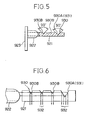
- FIG. 6 when an LED 922 is lit, the light is transmitted through the display plate 921 to each of the light reflectors 930 and 931, and the light is reflected to the front of the unit. The light reflected by the light reflectors 930 and 931 can be easily seen, and the presence of the discs 12 in the positions corresponding to each of the light reflectors 930 and 931 can be accurately confirmed.
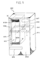
- FIG. 1 is a perspective view showing a construction of the auto disc changer 901 with the disc confirmation apparatus according to the present invention.
- the auto disc changer 901 according to the present invention has a disc stocker 913 in which a number of discs 12 can be stored, a carriage 914 which transfers a specified disc 12, a playback block (not shown) for playing back a specific disc 12, and a control block, all located in a cabinet 911.
- a tray 916 which loads and removes the discs 12 is positioned below the window 915.
- a display 917 which indicates the number representing the disc storage positions 913A in which a disc 12 is stored, and operation keys 918 are positioned at the right side of the transparent window 915.
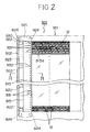
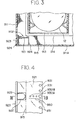
- the disc confirmation apparatus 902 by which the user can confirm the presence of stored discs 12 in the stocker 913, is positioned adjacent to the stocker 913 inside the unit so as to be visible from the transparent window 915 as shown in FIG. 2 and FIG. 3.
- the disc confirmation apparatus 902 is positioned adjacent to the discs 12 in the stocker 913 from a frontal point of view.
- the disc confirmation apparatus 902 is comprised of a display plate 921 the height of which is at least equal to the height of the stocker 913, a number of light-emitting means, for example, LEDs 922 which are positioned at regular intervals on the display plate 921, and a board 923 which controls the LEDs 922.
- the transparent display plate 921 is made of a transparent material, for example, acrylic fiber, and is mounted as close to the stocker 913 as possible without interfering with the carriage 914.
- the display plate 921 is attached by an appropriate means to four supports 924 formed on the upper and lower sides of the cabinet 911.
- the light reflectors 930 and 931 are V-shaped grooves cut into the display plate 921, as described below.
- the board 923 on which the LEDs 922 are mounted meets the left edge of the transparent display plate 921 at a right angle, and is attached to the cabinet 911.
- the LEDs 922 are positioned in the square cuts formed into the display plate 921 as shown in FIG. 4.
- the first light reflectors 930 and the second.light reflectors 931 are V-shaped cuts on the surface of the display plate 921. As shown in FIG. 4, each of the second light reflectors 931 is cut into the transparent display plate 921 and corresponds to one of the disc storage positions 913A.
- the first light reflector 930 is comprised of a larger V-shaped cut (reflector) 930A, and three smaller V-shaped cuts (reflectors) 930B arranged horizontally in a row with the larger reflector 930A closest to the stocker 913.
- the first light reflectors 930 are positioned at the first level, the 10th level, the 20th level, and so on, in increments of 10, to the uppermost level, the 100th level in this embodiment.
- the LED 922 is positioned just beside the first light reflector 930.
- these light reflectors 930 and 931 are V-shaped right-angled cuts in the back surface of the display plate, opened towards the rear of the unit.
- the LED 922 emits light
- the light is transmitted through the transparent display plate 921, is reflected on the surfaces 930A and 930B, inclined at 45° of the first and second light reflectors 930 and 931, and the reflected light 932 is transmitted to the front of the unit. From the front, only the reflectors 930 and 931 reflect light to the user, so that the user can easily recognize each of the light reflectors 930 and 931.
- the display plate 921 is positioned close to the discs 12, even when the user views the transparent window 915 from an angle, the positions of the light reflectors 930 and 931 do not deviate from the positions of the discs 12, so that the user can accurately confirm the presence of stored discs 12.
- first and second light reflectors 930 and 931 are V-shaped cuts with 90° angles in this embodiment, it is possible to use an angle other than 90° , and also possible to use a different shape of cut so long as the light can be reflected toward the front of the unit.
- the first and second light reflectors 930 and 931 are V-shaped cuts
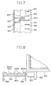
- the first and second light reflectors 940 and 941 can be made of square cuts with light reflecting angles as shown in FIG. 7, with the first light reflector 940 being longer than the second light reflectors 941 so that the user can distinguish between the two.
- the labeling means 942 by which numbers (1, 10 ... 100) representing the disc storage positions 913A are indicated, corresponding the first light reflectors, for example, may be in the form of Arabic numerals, characters, or other signs. In this embodiment, Arabic numerals are used.
- Such means 942 are also made as a V-shaped cuts, so that the numerals receiving the light from the LEDs 922 are illuminated as well, and the user can easily distinguish between them.
- the number of the LEDs 922 can be changed as long as the light reaches all of the light reflectors 930, 931, 940, and 941. Further, when different colors of light from the LEDs 922 can be used, creating a more colorful effect and making review of the disc storage positions 913A more easy. Moreover, all of the stocker 913 may be lit simultaneously, or only selected LEDs 922 may be used. For example, the LED 922 corresponding to the storage position 913A of the disc 12 which is being played back, may be selected separately.
- the LEDs 922 can be attached to areas other than the display plate 921; for example, to a board 950 attached on the carriage 914 as shown in FIG. 8.
- the display plate 921 and the LED 922 are positioned so that light from the LED 922 is transmitted from the right edge of the display plate 921.
- the LED 922 may be turned on and off, and when the carriage 914 stops, the LED 922 may be continuously lit. Accordingly, the user can easily determine whether or not the carriage 914 is moving or is stopped.
- the LEDs 922 may be positioned beside the display plate 921 and one or more LEDs 922 may be attached to the carriage 914.
- the display plate is positioned close to the discs in the stocker, the positions of the light reflectors do not deviate from the positions of the discs. Further, because the light reflectors are lit, the user can easily locate the position of the disc and accurately confirm the presence of stored discs.
Landscapes
- Automatic Disk Changers (AREA)
Claims (6)
- Eine Vorrichtung zur Bestätigung von Platten für eine Plattenlagereinrichtung, durch welche ein Benutzer die Anwesenheit einer in der Lagereinrichtung (913) gelagerten Platte (12) bestätigen kann, welche eine transparente Anzeigeplatte (921) umfasst, deren Höhe ausreicht, um sich über alle Plattenlagerpositionen der Plattenlagereinrichtung (913) zu erstrecken,
dadurch gekennzeichnet, dass die Vorrichtung des weiteren umfasst:erste Lichtreflektoren (930), eingeformt in die transparente Anzeigeplatte (921), welche einer vorgegebenen Anzahl der Plattenlagerpositionen entsprechen,zweite Lichtreflektoren (931), eingeformt in die transparente Anzeigeplatte (921), welche anderen Plattenlagerpositionen entsprechen, die nicht den ersten Lichtreflektoren (930) entsprechen, undLeuchtmittel (922) zum Abstrahlen von Licht auf die ersten und zweiten Lichtreflektoren (930, 931). - Die Vorrichtung zur Bestätigung von Platten nach Anspruch 1, bei der die ersten und zweiten Lichtreflektoren (930, 931) 90° V-förmige Einschnitte sind.
- Die Vorrichtung zur Bestätigung von Platten nach Anspruch 1, bei der das Leuchtmittel (922) an Transportmitteln (914) angebracht ist, welche die Platte zu und von der Plattenlagereinrichtung (913) transferieren.
- Die Vorrichtung zur Bestätigung von Platten nach Anspruch 1, bei der die ersten Lichtreflektoren (930) Kennzeichnungsmittel (942) aufweisen, durch welche der Benutzer die Plattenlagerpositionen ermitteln kann, die den ersten Lichtreflektoren entsprechen.
- Die Vorrichtung zur Bestätigung von Platten nach Anspruch 1, bei der nur dasjenige Leuchtmittel (922), welches aus einer Vielzahl von Leuchtmitteln (922) ausgewählt wird, beleuchtet wird.
- Die Vorrichtung zur Bestätigung von Platten nach Anspruch 1, bei der eine Vielzahl besagter Leuchtmittel (922) Licht in zwei oder mehreren verschiedenen Farben abstrahlt.
Applications Claiming Priority (6)
| Application Number | Priority Date | Filing Date | Title |
|---|---|---|---|
| JP22827294 | 1994-09-22 | ||
| JP228272/94 | 1994-09-22 | ||
| JP22827294A JPH0896479A (ja) | 1994-09-22 | 1994-09-22 | ディスクオートチェンジャ |
| JP297442/94 | 1994-11-30 | ||
| JP29744294A JP3392962B2 (ja) | 1994-11-30 | 1994-11-30 | ディスク収納棚のディスク確認装置 |
| JP29744294 | 1994-11-30 |
Publications (3)
| Publication Number | Publication Date |
|---|---|
| EP0703578A2 EP0703578A2 (de) | 1996-03-27 |
| EP0703578A3 EP0703578A3 (de) | 1996-08-28 |
| EP0703578B1 true EP0703578B1 (de) | 2001-02-07 |
Family
ID=26528151
Family Applications (1)
| Application Number | Title | Priority Date | Filing Date |
|---|---|---|---|
| EP95114895A Expired - Lifetime EP0703578B1 (de) | 1994-09-22 | 1995-09-21 | Automatischer Plattenwechsler |
Country Status (3)
| Country | Link |
|---|---|
| US (1) | US6058080A (de) |
| EP (1) | EP0703578B1 (de) |
| DE (1) | DE69520060T2 (de) |
Families Citing this family (6)
| Publication number | Priority date | Publication date | Assignee | Title |
|---|---|---|---|---|
| DE19636631A1 (de) * | 1996-09-10 | 1998-03-12 | Nsm Ag | Wiedergabe- und/oder Aufzeichnungsgerät für Platten |
| US6301219B1 (en) * | 1996-10-09 | 2001-10-09 | Sony Corporation | Device of loading recording medium |
| JP2000113556A (ja) * | 1998-09-30 | 2000-04-21 | Mitsubishi Electric Corp | ライブラリ装置 |
| JP2003091983A (ja) * | 2001-09-18 | 2003-03-28 | Mitsumi Electric Co Ltd | 記録再生装置 |
| US6816332B2 (en) * | 2002-06-25 | 2004-11-09 | International Business Machines Corporation | Vertical and horizontal path sensing within a data storage and retrieval system |
| US20060146658A1 (en) * | 2004-12-30 | 2006-07-06 | Microboards Technology, Llc | Memory storage handling system |
Family Cites Families (17)
| Publication number | Priority date | Publication date | Assignee | Title |
|---|---|---|---|---|
| JPS6040560A (ja) * | 1983-08-12 | 1985-03-02 | Pioneer Electronic Corp | デイスク演奏装置 |
| US4685095A (en) * | 1984-07-11 | 1987-08-04 | Filenet Corporation | Optical storage and retrieval device |
| JPS63104258A (ja) * | 1986-10-22 | 1988-05-09 | Pioneer Electronic Corp | マルチデイスクプレ−ヤの駆動制御方式 |
| DE3638912A1 (de) * | 1986-11-14 | 1988-05-26 | Thomson Brandt Gmbh | Magazin fuer plattenfoermige aufzeichnungstraeger |
| DE3871209D1 (de) * | 1987-03-27 | 1992-06-25 | Mitsubishi Electric Corp | Geraet zum speichern und transport von platten. |
| JPH0731402Y2 (ja) * | 1987-06-15 | 1995-07-19 | パイオニア株式会社 | カートリッジ収納ディスク再生装置 |
| JPS6450274A (en) * | 1987-08-21 | 1989-02-27 | Pioneer Electronic Corp | Auto-changer type disk player |
| US4929866A (en) * | 1987-11-17 | 1990-05-29 | Mitsubishi Cable Industries, Ltd. | Light emitting diode lamp |
| US5084859A (en) * | 1988-07-15 | 1992-01-28 | Pioneer Electronic Corporation | Multi-magazine disc player |
| US5191569A (en) * | 1989-05-15 | 1993-03-02 | Pioneer Electronic Corporation | Disk playback device |
| JPH03256260A (ja) * | 1990-03-07 | 1991-11-14 | Pioneer Electron Corp | マルチタイプcdプレーヤシステム |
| US5130761A (en) * | 1990-07-17 | 1992-07-14 | Kabushiki Kaisha Toshiba | Led array with reflector and printed circuit board |
| AU8526491A (en) * | 1990-09-03 | 1992-03-30 | Stefan Gustafsson | A system intended for theft-proof selling of cd records or the like and a computer controlled storage unit and a display unit usable in the system |
| JPH04353664A (ja) * | 1991-05-30 | 1992-12-08 | Pioneer Electron Corp | ディスクプレーヤ |
| US5264974A (en) * | 1991-09-30 | 1993-11-23 | Campbell Kenneth C | Cassette loading system |
| JPH06243568A (ja) * | 1993-02-22 | 1994-09-02 | Tanashin Denki Co | ディスク再生装置 |
| JPH06349186A (ja) * | 1993-06-03 | 1994-12-22 | Nakamichi Corp | ディスク再生装置 |
-
1995
- 1995-09-18 US US08/529,667 patent/US6058080A/en not_active Expired - Fee Related
- 1995-09-21 EP EP95114895A patent/EP0703578B1/de not_active Expired - Lifetime
- 1995-09-21 DE DE69520060T patent/DE69520060T2/de not_active Expired - Fee Related
Also Published As
| Publication number | Publication date |
|---|---|
| DE69520060T2 (de) | 2001-09-06 |
| DE69520060D1 (de) | 2001-03-15 |
| EP0703578A2 (de) | 1996-03-27 |
| US6058080A (en) | 2000-05-02 |
| EP0703578A3 (de) | 1996-08-28 |
Similar Documents
| Publication | Publication Date | Title |
|---|---|---|
| JP6831129B1 (ja) | 遊技機 | |
| US5228015A (en) | Musical reproduction unit | |
| US5225818A (en) | Data entry control panel | |
| US4772097A (en) | Light controlling sheet | |
| US7265307B2 (en) | Illumination push switch unit | |
| CN101135429A (zh) | 发光装置 | |
| US20230041435A1 (en) | Operating unit and amusement machine | |
| US20060120106A1 (en) | Illumination apparatus | |
| US6058080A (en) | Disc-position display for auto disc changer | |
| CA1228686A (en) | Display device for telephone or the like electric appliance | |
| US20050078815A1 (en) | Self-lighting type push button input device | |
| JP3091592U (ja) | ディスクドライブ装置および電子機器 | |
| JP2000042181A (ja) | 遊技機 | |
| JPS63172189A (ja) | 表示装置 | |
| JPS61274291A (ja) | 通信光学機器の操作部材を有するフロントパネル | |
| JP2004354478A (ja) | 表示装置およびこの表示装置を備えた電子機器 | |
| US12222529B2 (en) | Display switching device, button device for game machine, and switch | |
| EP1542224B1 (de) | Plattenlaufwerk | |
| JP3392962B2 (ja) | ディスク収納棚のディスク確認装置 | |
| JP4294636B2 (ja) | 遊技機 | |
| US11397292B2 (en) | Lighting display assembly | |
| JP4239146B2 (ja) | 遊技機用の発光装置 | |
| JP3401367B2 (ja) | Cdプレーヤ | |
| JP4282362B2 (ja) | 電子機器 | |
| JPH08138428A (ja) | 面光源装置を用いた表示装置 |
Legal Events
| Date | Code | Title | Description |
|---|---|---|---|
| PUAI | Public reference made under article 153(3) epc to a published international application that has entered the european phase |
Free format text: ORIGINAL CODE: 0009012 |
|
| AK | Designated contracting states |
Kind code of ref document: A2 Designated state(s): DE FR GB IT NL |
|
| PUAL | Search report despatched |
Free format text: ORIGINAL CODE: 0009013 |
|
| AK | Designated contracting states |
Kind code of ref document: A3 Designated state(s): DE FR GB IT NL |
|
| 17P | Request for examination filed |
Effective date: 19970214 |
|
| 17Q | First examination report despatched |
Effective date: 19970318 |
|
| GRAG | Despatch of communication of intention to grant |
Free format text: ORIGINAL CODE: EPIDOS AGRA |
|
| GRAG | Despatch of communication of intention to grant |
Free format text: ORIGINAL CODE: EPIDOS AGRA |
|
| GRAH | Despatch of communication of intention to grant a patent |
Free format text: ORIGINAL CODE: EPIDOS IGRA |
|
| GRAH | Despatch of communication of intention to grant a patent |
Free format text: ORIGINAL CODE: EPIDOS IGRA |
|
| GRAA | (expected) grant |
Free format text: ORIGINAL CODE: 0009210 |
|
| AK | Designated contracting states |
Kind code of ref document: B1 Designated state(s): DE FR GB IT NL |
|
| REF | Corresponds to: |
Ref document number: 69520060 Country of ref document: DE Date of ref document: 20010315 |
|
| ITF | It: translation for a ep patent filed | ||
| ET | Fr: translation filed | ||
| PGFP | Annual fee paid to national office [announced via postgrant information from national office to epo] |
Ref country code: NL Payment date: 20010928 Year of fee payment: 7 |
|
| PLBE | No opposition filed within time limit |
Free format text: ORIGINAL CODE: 0009261 |
|
| STAA | Information on the status of an ep patent application or granted ep patent |
Free format text: STATUS: NO OPPOSITION FILED WITHIN TIME LIMIT |
|
| REG | Reference to a national code |
Ref country code: GB Ref legal event code: IF02 |
|
| 26N | No opposition filed | ||
| PG25 | Lapsed in a contracting state [announced via postgrant information from national office to epo] |
Ref country code: NL Free format text: LAPSE BECAUSE OF NON-PAYMENT OF DUE FEES Effective date: 20030401 |
|
| PGFP | Annual fee paid to national office [announced via postgrant information from national office to epo] |
Ref country code: FR Payment date: 20030909 Year of fee payment: 9 |
|
| PGFP | Annual fee paid to national office [announced via postgrant information from national office to epo] |
Ref country code: GB Payment date: 20030917 Year of fee payment: 9 |
|
| PGFP | Annual fee paid to national office [announced via postgrant information from national office to epo] |
Ref country code: DE Payment date: 20031002 Year of fee payment: 9 |
|
| PG25 | Lapsed in a contracting state [announced via postgrant information from national office to epo] |
Ref country code: GB Free format text: LAPSE BECAUSE OF NON-PAYMENT OF DUE FEES Effective date: 20040921 |
|
| PG25 | Lapsed in a contracting state [announced via postgrant information from national office to epo] |
Ref country code: DE Free format text: LAPSE BECAUSE OF NON-PAYMENT OF DUE FEES Effective date: 20050401 |
|
| GBPC | Gb: european patent ceased through non-payment of renewal fee |
Effective date: 20040921 |
|
| PG25 | Lapsed in a contracting state [announced via postgrant information from national office to epo] |
Ref country code: FR Free format text: LAPSE BECAUSE OF NON-PAYMENT OF DUE FEES Effective date: 20050531 |
|
| REG | Reference to a national code |
Ref country code: FR Ref legal event code: ST |
|
| PG25 | Lapsed in a contracting state [announced via postgrant information from national office to epo] |
Ref country code: IT Free format text: LAPSE BECAUSE OF NON-PAYMENT OF DUE FEES;WARNING: LAPSES OF ITALIAN PATENTS WITH EFFECTIVE DATE BEFORE 2007 MAY HAVE OCCURRED AT ANY TIME BEFORE 2007. THE CORRECT EFFECTIVE DATE MAY BE DIFFERENT FROM THE ONE RECORDED. Effective date: 20050921 |