EP0703692A2 - Appareil et méthode d'enregistrement et de reproduction d'un message vocal - Google Patents
Appareil et méthode d'enregistrement et de reproduction d'un message vocal Download PDFInfo
- Publication number
- EP0703692A2 EP0703692A2 EP95113377A EP95113377A EP0703692A2 EP 0703692 A2 EP0703692 A2 EP 0703692A2 EP 95113377 A EP95113377 A EP 95113377A EP 95113377 A EP95113377 A EP 95113377A EP 0703692 A2 EP0703692 A2 EP 0703692A2
- Authority
- EP
- European Patent Office
- Prior art keywords
- data
- communication
- speech
- facsimile
- radio
- Prior art date
- Legal status (The legal status is an assumption and is not a legal conclusion. Google has not performed a legal analysis and makes no representation as to the accuracy of the status listed.)
- Withdrawn
Links
- 238000000034 method Methods 0.000 title claims abstract description 25
- 238000004891 communication Methods 0.000 claims abstract description 134
- 230000003287 optical effect Effects 0.000 claims abstract description 40
- 230000005540 biological transmission Effects 0.000 claims abstract description 24
- 238000007639 printing Methods 0.000 claims abstract description 10
- 238000013500 data storage Methods 0.000 claims description 31
- 230000005236 sound signal Effects 0.000 claims description 30
- 230000004044 response Effects 0.000 claims description 7
- 230000002093 peripheral effect Effects 0.000 claims description 6
- 238000001514 detection method Methods 0.000 claims description 3
- 230000000694 effects Effects 0.000 claims description 2
- 238000012545 processing Methods 0.000 description 28
- 238000010586 diagram Methods 0.000 description 9
- 230000015556 catabolic process Effects 0.000 description 3
- 238000006731 degradation reaction Methods 0.000 description 3
- 238000012549 training Methods 0.000 description 3
- 238000005516 engineering process Methods 0.000 description 2
- 230000006870 function Effects 0.000 description 2
- 238000012986 modification Methods 0.000 description 2
- 230000004048 modification Effects 0.000 description 2
- 230000003252 repetitive effect Effects 0.000 description 2
- 230000003044 adaptive effect Effects 0.000 description 1
- 238000007906 compression Methods 0.000 description 1
- 230000006835 compression Effects 0.000 description 1
- 238000012790 confirmation Methods 0.000 description 1
- 238000013144 data compression Methods 0.000 description 1
- 238000009434 installation Methods 0.000 description 1
- 238000003825 pressing Methods 0.000 description 1
- 238000001454 recorded image Methods 0.000 description 1
- 239000004065 semiconductor Substances 0.000 description 1
- 238000010561 standard procedure Methods 0.000 description 1
- 239000013589 supplement Substances 0.000 description 1
- 238000012546 transfer Methods 0.000 description 1
- 230000007704 transition Effects 0.000 description 1
Images


Classifications
-
- H—ELECTRICITY
- H04—ELECTRIC COMMUNICATION TECHNIQUE
- H04N—PICTORIAL COMMUNICATION, e.g. TELEVISION
- H04N1/00—Scanning, transmission or reproduction of documents or the like, e.g. facsimile transmission; Details thereof
- H04N1/00127—Connection or combination of a still picture apparatus with another apparatus, e.g. for storage, processing or transmission of still picture signals or of information associated with a still picture
- H04N1/00281—Connection or combination of a still picture apparatus with another apparatus, e.g. for storage, processing or transmission of still picture signals or of information associated with a still picture with a telecommunication apparatus, e.g. a switched network of teleprinters for the distribution of text-based information, a selective call terminal
- H04N1/00302—Connection or combination of a still picture apparatus with another apparatus, e.g. for storage, processing or transmission of still picture signals or of information associated with a still picture with a telecommunication apparatus, e.g. a switched network of teleprinters for the distribution of text-based information, a selective call terminal with a telephonic apparatus, e.g. telephone answering machine or videotex terminal
-
- H—ELECTRICITY
- H04—ELECTRIC COMMUNICATION TECHNIQUE
- H04M—TELEPHONIC COMMUNICATION
- H04M1/00—Substation equipment, e.g. for use by subscribers
- H04M1/26—Devices for calling a subscriber
- H04M1/27—Devices whereby a plurality of signals may be stored simultaneously
- H04M1/274—Devices whereby a plurality of signals may be stored simultaneously with provision for storing more than one subscriber number at a time, e.g. using toothed disc
- H04M1/2745—Devices whereby a plurality of signals may be stored simultaneously with provision for storing more than one subscriber number at a time, e.g. using toothed disc using static electronic memories, e.g. chips
- H04M1/2753—Devices whereby a plurality of signals may be stored simultaneously with provision for storing more than one subscriber number at a time, e.g. using toothed disc using static electronic memories, e.g. chips providing data content
- H04M1/2755—Devices whereby a plurality of signals may be stored simultaneously with provision for storing more than one subscriber number at a time, e.g. using toothed disc using static electronic memories, e.g. chips providing data content by optical scanning
-
- H—ELECTRICITY
- H04—ELECTRIC COMMUNICATION TECHNIQUE
- H04M—TELEPHONIC COMMUNICATION
- H04M1/00—Substation equipment, e.g. for use by subscribers
- H04M1/57—Arrangements for indicating or recording the number of the calling subscriber at the called subscriber's set
-
- H—ELECTRICITY
- H04—ELECTRIC COMMUNICATION TECHNIQUE
- H04M—TELEPHONIC COMMUNICATION
- H04M1/00—Substation equipment, e.g. for use by subscribers
- H04M1/64—Automatic arrangements for answering calls; Automatic arrangements for recording messages for absent subscribers; Arrangements for recording conversations
- H04M1/65—Recording arrangements for recording a message from the calling party
- H04M1/6505—Recording arrangements for recording a message from the calling party storing speech in digital form
-
- H—ELECTRICITY
- H04—ELECTRIC COMMUNICATION TECHNIQUE
- H04M—TELEPHONIC COMMUNICATION
- H04M1/00—Substation equipment, e.g. for use by subscribers
- H04M1/72—Mobile telephones; Cordless telephones, i.e. devices for establishing wireless links to base stations without route selection
- H04M1/725—Cordless telephones
-
- H—ELECTRICITY
- H04—ELECTRIC COMMUNICATION TECHNIQUE
- H04N—PICTORIAL COMMUNICATION, e.g. TELEVISION
- H04N1/00—Scanning, transmission or reproduction of documents or the like, e.g. facsimile transmission; Details thereof
- H04N1/00127—Connection or combination of a still picture apparatus with another apparatus, e.g. for storage, processing or transmission of still picture signals or of information associated with a still picture
- H04N1/00326—Connection or combination of a still picture apparatus with another apparatus, e.g. for storage, processing or transmission of still picture signals or of information associated with a still picture with a data reading, recognizing or recording apparatus, e.g. with a bar-code apparatus
- H04N1/00328—Connection or combination of a still picture apparatus with another apparatus, e.g. for storage, processing or transmission of still picture signals or of information associated with a still picture with a data reading, recognizing or recording apparatus, e.g. with a bar-code apparatus with an apparatus processing optically-read information
- H04N1/00334—Connection or combination of a still picture apparatus with another apparatus, e.g. for storage, processing or transmission of still picture signals or of information associated with a still picture with a data reading, recognizing or recording apparatus, e.g. with a bar-code apparatus with an apparatus processing optically-read information with an apparatus processing barcodes or the like
-
- H—ELECTRICITY
- H04—ELECTRIC COMMUNICATION TECHNIQUE
- H04N—PICTORIAL COMMUNICATION, e.g. TELEVISION
- H04N1/00—Scanning, transmission or reproduction of documents or the like, e.g. facsimile transmission; Details thereof
- H04N1/32—Circuits or arrangements for control or supervision between transmitter and receiver or between image input and image output device, e.g. between a still-image camera and its memory or between a still-image camera and a printer device
- H04N1/32101—Display, printing, storage or transmission of additional information, e.g. ID code, date and time or title
- H04N1/32106—Display, printing, storage or transmission of additional information, e.g. ID code, date and time or title separate from the image data, e.g. in a different computer file
- H04N1/32122—Display, printing, storage or transmission of additional information, e.g. ID code, date and time or title separate from the image data, e.g. in a different computer file in a separate device, e.g. in a memory or on a display separate from image data
-
- H—ELECTRICITY
- H04—ELECTRIC COMMUNICATION TECHNIQUE
- H04N—PICTORIAL COMMUNICATION, e.g. TELEVISION
- H04N2201/00—Indexing scheme relating to scanning, transmission or reproduction of documents or the like, and to details thereof
- H04N2201/0008—Connection or combination of a still picture apparatus with another apparatus
- H04N2201/0034—Details of the connection, e.g. connector, interface
- H04N2201/0048—Type of connection
- H04N2201/0055—By radio
-
- H—ELECTRICITY
- H04—ELECTRIC COMMUNICATION TECHNIQUE
- H04N—PICTORIAL COMMUNICATION, e.g. TELEVISION
- H04N2201/00—Indexing scheme relating to scanning, transmission or reproduction of documents or the like, and to details thereof
- H04N2201/32—Circuits or arrangements for control or supervision between transmitter and receiver or between image input and image output device, e.g. between a still-image camera and its memory or between a still-image camera and a printer device
- H04N2201/3201—Display, printing, storage or transmission of additional information, e.g. ID code, date and time or title
- H04N2201/3225—Display, printing, storage or transmission of additional information, e.g. ID code, date and time or title of data relating to an image, a page or a document
- H04N2201/3243—Display, printing, storage or transmission of additional information, e.g. ID code, date and time or title of data relating to an image, a page or a document of type information, e.g. handwritten or text document
-
- H—ELECTRICITY
- H04—ELECTRIC COMMUNICATION TECHNIQUE
- H04N—PICTORIAL COMMUNICATION, e.g. TELEVISION
- H04N2201/00—Indexing scheme relating to scanning, transmission or reproduction of documents or the like, and to details thereof
- H04N2201/32—Circuits or arrangements for control or supervision between transmitter and receiver or between image input and image output device, e.g. between a still-image camera and its memory or between a still-image camera and a printer device
- H04N2201/3201—Display, printing, storage or transmission of additional information, e.g. ID code, date and time or title
- H04N2201/3261—Display, printing, storage or transmission of additional information, e.g. ID code, date and time or title of multimedia information, e.g. a sound signal
- H04N2201/3264—Display, printing, storage or transmission of additional information, e.g. ID code, date and time or title of multimedia information, e.g. a sound signal of sound signals
-
- H—ELECTRICITY
- H04—ELECTRIC COMMUNICATION TECHNIQUE
- H04N—PICTORIAL COMMUNICATION, e.g. TELEVISION
- H04N2201/00—Indexing scheme relating to scanning, transmission or reproduction of documents or the like, and to details thereof
- H04N2201/32—Circuits or arrangements for control or supervision between transmitter and receiver or between image input and image output device, e.g. between a still-image camera and its memory or between a still-image camera and a printer device
- H04N2201/3201—Display, printing, storage or transmission of additional information, e.g. ID code, date and time or title
- H04N2201/3269—Display, printing, storage or transmission of additional information, e.g. ID code, date and time or title of machine readable codes or marks, e.g. bar codes or glyphs
-
- H—ELECTRICITY
- H04—ELECTRIC COMMUNICATION TECHNIQUE
- H04N—PICTORIAL COMMUNICATION, e.g. TELEVISION
- H04N2201/00—Indexing scheme relating to scanning, transmission or reproduction of documents or the like, and to details thereof
- H04N2201/32—Circuits or arrangements for control or supervision between transmitter and receiver or between image input and image output device, e.g. between a still-image camera and its memory or between a still-image camera and a printer device
- H04N2201/3201—Display, printing, storage or transmission of additional information, e.g. ID code, date and time or title
- H04N2201/3271—Printing or stamping
-
- H—ELECTRICITY
- H04—ELECTRIC COMMUNICATION TECHNIQUE
- H04N—PICTORIAL COMMUNICATION, e.g. TELEVISION
- H04N2201/00—Indexing scheme relating to scanning, transmission or reproduction of documents or the like, and to details thereof
- H04N2201/32—Circuits or arrangements for control or supervision between transmitter and receiver or between image input and image output device, e.g. between a still-image camera and its memory or between a still-image camera and a printer device
- H04N2201/3201—Display, printing, storage or transmission of additional information, e.g. ID code, date and time or title
- H04N2201/3274—Storage or retrieval of prestored additional information
Definitions
- the present invention relates to a method of recording/reproducing of a transmitted speech message associated with a facsimile document and a communication apparatus for use in such a method and, more particularly, to a speech message recording/reproducing method with simplified operation and security of privacy at speech message reproduction and a communication apparatus for use in such a method.
- a voice contact reservation capability for a facsimile communication apparatus has been developed. This capability switches the same telephone line from image transmission mode to speech mode upon termination of image transmission without disconnecting the circuit. This capability assumes that the receiving side is attended by an operator for responding to the voice communication.
- the receiving side may however be unattended.
- the speech message is recorded on an automatic answering telephone.
- the standard facsimile communication protocol does not specify a procedure for recording a speech message on the automatic answering telephone (this recording is also called registration hereinafter) after image transmission, thereby requiring a unique idea for operatively linking the voice contact reservation capability with the automatic answering telephone capability.
- Japanese Non-examined Patent Publication No. 5-300359 discloses an apparatus having an automatic call terminating section for detecting a conversation request signal sent from a sender to perform an automatic off-hook operation after a predetermined number of rings, thereby recording the speech message automatically.
- Japanese Non-examined Patent Publication No. 5-227347 discloses an apparatus having a dial-tone recognizing unit for controlling circuit switching by a tone signal wherein the circuit switching is switched to the registration mode.
- facsimile transmission is performed prior to speech message recording.
- a oppositely operating apparatus has also been proposed in which the facsimile receive operation follows speech message recording.
- Japanese Non-examined Patent Publication No. 5-300294 discloses that the start and end of a speech message are notified by means of tone signals, upon which facsimile transmission is performed.
- Japanese Non-examined Patent Publication No. 5-300293 discloses an apparatus for detecting a no-signal state beyond a predetermined time interval to switch to facsimile transmission.
- a plurality of pieces of image data and speech data are received and stored to be displayed, in a list form, on an LCD panel attached to the facsimile communication apparatus.
- an image specified by an operator is displayed and then a speech message associated with the displayed image is outputted from the speaker (Japanese Non-examined Patent Publication No. 5-300293).
- This publication also discloses, in another embodiment, a case in which image data is not stored in memory but outputted directly to a printer. If speech data is attached to the image data, the fact of the attachment and the storage number of the speech data are printed on the paper. The operator enters the number to obtain reproduction of the speech message from the speaker.
- the facsimile communication apparatus has been increasingly reduced in size and price, and is being used in an increasing number of families.
- contents of communication are mostly personal information, thus requiring confidentiality of communication compared with an office application.
- a household application is characterized more by entertainment such as the sending of a birthday card along with a speech message than merely retrieving information. In such an application, repeated reproduction is assumed.
- speech data reproduction is restricted to the speaker of the facsimile apparatus.
- a facsimile machine dedicated to each family member needs to be installed, which increases installation cost.
- each addressee is required to go to the facsimile installed location, thereby reducing the convenience of operation.
- most conventional facsimile apparatuses are insufficient in providing a simple, easy-to-use family user interface.
- a communication apparatus comprising: a facsimile communication unit for outputting received image data and other communication data; a first handset having a transmitter microphone and a receiver speaker; a speech data storage unit for storing an audio signal or coded speech data according to specified address information, the stored information being outputted for any specified address; a circuit connecting unit for accepting operator entered data, distributing the operator entered data to peripheral units as required, performing calling and call-incoming control on a network, having a transmitter path and a receiver path for the audio signal, connecting the handset to both the paths, and selecting the facsimile communication unit or one of the paths for connection to the network; a first radio communication unit for communicating a first audio signal passing the path connected to the network, a second audio signal or speech data outputted from the speech data storage unit, and other communication data with an apparatus located at the other end of a radio path; a control unit for receiving communication data coming from the facsimile communication unit and communication data coming from the apparatus located at the other end of the
- At least one portable station unit powered by a battery is provided at the other end of the radio path to which the base station is connected, the portable station unit comprising; a second handset, a second radio communication unit for transmitting and receiving the audio signal or the speech data and other communication data, and an optical reading unit connected to the second radio communication unit, the optical reading unit enabling detecting and interpreting of a printed optical pattern to convert the detected and interpreted pattern to communication data.
- the base station is set to the automatic answering mode by the operator through the circuit connecting unit. Then based on the operator data, the control unit also recognizes the automatic answering mode.
- the circuit connecting unit detects the reception of a facsimile image to connect the signal of the network side to the facsimile communication unit. Then, if a voice contact is requested from the calling side by such operation as the voice contact reservation during the facsimile communication, the control unit detects the request from the communication data outputted by the facsimile communication unit and, following the procedure discontinuation processing for the termination of facsimile image transmission, instructs the circuit connecting unit to switch the connection to the audio path side.
- the circuit connecting unit sets the audio path.
- the control unit also outputs the address information (a) of an automatic answer message stored in the speech data storage unit in advance and, at the same time, instructs the network to set the audio path for transmitting the automatic answer message.
- the calling operator can hear the above-mentioned answer message to know that the called side is in the automatic answering mode. Following the answer message, the calling operator sends his or her speech message.
- This speech message is stored in the speech data storage unit via the audio path according to the address information (b) specified by the control unit.
- the address information (b) for recording is determined in the control unit when the voice contact reservation has been detected by means of the procedure discontinuation processing signal or the like at the latest. Consequently, the optical pattern data generation unit may convert and output print data based on the address information (b) immediately after reception of the facsimile image.
- the image recording unit attaches the address information in a predetermined format according to the print data. As a result, the facsimile image and the speech message can be recorded in an associated manner.
- the address information of the print output is detected and interpreted by the optical reading unit incorporated in the portable station unit to be converted to communication data.
- the communication data is sent by the second radio communication unit to the base station.
- the control unit receives the address information (b) via the first radio communication unit to recognize the instruction for reproducing the message. Then, the control unit instructs the audio path of the circuit connecting unit to output the audio signal or speech data outputted from the speech data storage unit to the first radio communication unit and, at the same time, outputs the received address information (b) to the speech data storage unit as the reproduction address.
- the audio signal or speech data outputted from the speech data storage unit is transmitted from the first radio communication unit to the second radio communication unit to be outputted to the operator of the portable station unit via the handset.
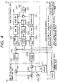
- FIG. 1 is a block diagram illustrating a communication apparatus according to an embodiment of the present invention.
- a public network 1 a base station 2, portable station 3, and a printed facsimile document 4 having a bar code 40 printed thereon.
- the base station 2 there is provided a circuit connecting unit 20, a control unit 21, a base station radio unit 22, a facsimile terminal 23, an image recording unit 24, a bar code pattern generation unit 25, a speech data storage unit 26 and a handset 27.
- the base station 2 is constituted as a cordless telephone base station.
- the portable station 3 there is provided a portable station radio unit 30, a bar code reader 31 and a bar code alerter 310.
- the portable station 3 is constituted as a cordless telephone portable set.
- the circuit connecting unit 20, the facsimile terminal 23, and the control unit 21 correspond to the voice contact reservation capability based on known technologies that is switched to the registration mode without disconnecting the circuit.
- the circuit connecting unit 20 is connected with the handset 27 through which operator data is entered.
- the circuit connecting unit 20 controls calling and call-incoming operations for the public network 1 to output the operator data to a peripheral apparatus as required.
- the circuit connecting unit 20 has signal paths for transmitted and received audio signals. To these signal paths, the handset 27 is connected.
- the circuit connecting unit 20 also has a connection switching capability for connecting either the facsimile terminal 23 or the audio signal paths to the public network 1 according to a control procedure to be described later.
- the audio signal paths are also connected with the base station radio unit 22.
- the base station radio unit 22 performs radio communication with the portable station radio unit 30 located at the other end of the communication line via the radio section interface specified in the second-generation cordless telephone standards (RCR STD-28 issued by the Research and Development Center for Radio Systems Foundation).
- the audio signal is thus encoded by the adaptive differential pulse coding method (hereinafter referred to as ADPCM) of 32Kbps and the coded signal is transmitted as a digital phase modulated signal based on speech data.
- Speech messages are stored in a digital data format by using a speech coder (to be described with reference to Fig. 4) incorporated in the base station radio unit 22.
- the input/output signal line for the speech data coming from the base station radio unit 22 is connected to the speech data storage unit 26.
- the speech data storage unit 26 is composed of a semiconductor memory to reduce the dimensional size of the unit. For example, use of a flash ROM is considered in which a data quantity predetermined for one message to be recorded in the automatic answering mode provides one unit of erase block.
- the facsimile terminal 23 outputs the received image data to the image recording unit 24 via the circuit connecting unit 20 and other communication data (F) to the control unit 21.
- the control unit 21 performs overall control of the entire base station 2. More specifically, the control unit controls the facsimile communication and operations such as the associative operation of registration mode and the reproduction of speech messages. For this purpose, in addition to the communication data (F), the operator data from the circuit connecting unit 20 and the communication data (R) received by the base station radio unit 22 via the radio path are entered in the control unit.
- the control unit 21 has a control output for instructing the circuit connecting unit 20 to perform a calling operation, set a calling number, disconnect the telephone line, and set an internal audio signal path for recording/reproducing a speech message. Also, the control unit has another control output for instructing the base station radio unit 22 to control radio communication operations, set the speech data decoding and coding modes, and set a speech data connecting path. In addition, the control unit has yet another control output for instructing the facsimile terminal 23 to discontinue receive procedure processing.
- control unit 21 outputs storage address data and reproduction address data of speech data to the speech data storage unit 26. These address data are also outputted to the bar code pattern generation block 25, with an identification bit for discriminating between storage and reproduction. Further still, the control unit 21 outputs, to the bar code pattern generation unit 25, calling party information detected based on the received communication data of the facsimile terminal 23. In the present embodiment, this calling party information is specifically a telephone number of the calling party.
- the bar code pattern generation unit 25 generates data for printing a bar code from the storage address data and the calling party telephone number and outputs the generated data to the image recording unit 25.
- the image recording unit 25 adds bar code information to the received facsimile image data to print the resultant data in a predetermined format.
- FIG. 1 A schematic diagram illustrating a print example (the facsimile document 4) is shown in Fig. 1.
- bars of the bar code are printed in parallel with the paper feed direction of the image recording unit 24. This setup avoids the degradation of a bar code reading accuracy in which bar code line width and line interval play an important role, the degradation being caused by degradation of the paper feed of the image recording unit 24.
- the portable station 3 Connected to the base station 2 via the radio path is the portable station 3. Although only a single portable station is depicted in Fig. 1, there may be a plurality of portable stations.
- the portable station 3 is composed of the portable station radio unit 30 connected with the bar code reader 31 to transmit information read through the bar code reader 31 to the base station 2 as radio communication data.
- a communication procedure processing from facsimile reception to speech message recording as practiced in the present embodiment is described with reference to Fig. 2 utilizing reference numerals 500 through 520.
- the control unit 21 that has received the operator data has the registration mode set therein.
- a facsimile terminal on the sending or transmitting side not shown, has the voice contact reservation capability and can transmit a facsimile and a voice signal in a single call.
- the circuit connecting unit 20 Upon reception of the CNG signal, the circuit connecting unit 20 connects the facsimile terminal 23 to the public network 1 (step 501).
- the connected facsimile terminal 23 sends a CED signal to the facsimile on the other end of the line to tell it that the call-incoming terminal is a facsimile terminal (step 502).
- the preparation for transmission is made by using a binary-coded control signal.
- nonstandard function (NSF), called side identification (CSI), and digital identification signal (DIS) are sent from the call-incoming facsimile terminal 23 (step 503) to notify the calling facsimile terminal that the processing moves to a non-standard procedure unique to the present embodiment.
- a non-standard function setting NSS
- transmitting terminal identification TTI
- DCS digital command signal
- step 508 necessary image data is sent (step 508) and the call-incoming facsimile terminal 23 outputs the received image data to the image recording unit 24 (step 510).
- the calling operator (B) performs voice contact reservation during the facsimile transmission (step 509).
- a procedure interruption (PRI-EOI) is sent to keep the line connected after the transmission of image data (step 511).
- the control unit 21 that recognized the registration mode by the presetting detects the PRI-EOI via the communication data to output a storage address at which the speech message is to be recorded. From this address information and the calling party information sent at the beginning of the facsimile reception, bar code data is generated to be printed on an image printing paper like the image data (step 512).
- the receiving facsimile terminal 23 sends a procedure interruption positive (PIP) (step 513).
- PIP procedure interruption positive
- the transmitting facsimile terminal retransmits the PRI-EOI (step 514) and notifies the sending operator (B) with an alarm sound or a buzzer that the voice contact mode is on.
- the control unit 21 detects the PRI-EOI again from the communication data to instruct the circuit connecting unit 20 to switch the connection to the registration mode (step 515). As a result, based on the control by the control unit 21, the connecting unit sets an audio path to be described to send a response message to the calling side (step 516).
- the calling operator (B) recognizes that the call-incoming facsimile terminal 23 is not attended by the called operator (A) and, following a dial tone to be sent (step 517), the calling operator (B) enters a speech message (step 518).
- the speech message is entered in the speech data storage unit 26 at the storage address therefor (step 519).
- the control unit 21 instructs the circuit connecting unit 20 to disconnect the line (step 520).
- control unit 21 controls all of the operations as described above. Reorganized operations of the control unit 21 in the registration mode is described with reference to Fig. 3 which shows a flowchart of the processing steps by the control unit 21 in the registration mode, the steps being indicated by reference numerals 2100 through 2111.
- the control unit 21 recognizes the registration mode from the operator data (step 2100) and enters the state in which to monitor the communication data coming from the facsimile terminal 23 (step 2101).
- the control unit detects the PRI-EOI from the abovementioned communication data, the control unit outputs the calling party telephone number and the speech data storage address information to print a bar code on the facsimile document (step 2102).
- the control unit re-enters the state in which to monitor the PRI-EOI (step 2103). This state is provided with a time-out (step 2104). If the PRI-EOI is not detected within a predetermined time, the control unit instructs the circuit connecting unit to disconnect the line.
- control unit When the control unit detects the PRI-EOI again in step 2103, the control unit instructs the circuit connecting unit 20 to switch the line to the registration (step 2105) to connect the audio path for automatic answering message reproduction (step 2106, details to be described later). Then, the control unit outputs the automatic answering message reproduction address followed by the transmission of the automatic answering message (step 2107). After the transmission of the automatic answering message, the control unit instructs the circuit connecting unit to output a dial tone for requesting the recording of the speech message (step 2108), counts a predetermined recording time, and sequentially updates and outputs storage addresses until the time-out is detected (steps 2109 and 2110). Then, when the recording time has passed, the control unit instructs the circuit connecting unit 20 to disconnect the line (step 2111).
- Fig. 4 is a block diagram illustrating the relationship of the base station radio unit 22 with its peripheral devices.
- reference numerals 2001, 2002 and 2004 indicate selector switches and reference numeral 2003 indicates a speaker.
- reference numeral 2201 indicates a transmit/receive antenna
- reference numeral 2202 a top band-pass filter
- 2203 a receiver
- 2204 a demodulator
- 2205 a receive frame processing circuit
- 2206 a selector switch
- 2207 a speech decoder 2208 a speech coder
- 2209 a transmit frame processing circuit
- 2210 an IQ signal generator
- 2211 a transmitter 2212 a high-frequency switch
- 2213 a divider 2214 a frequency synthesizer
- reference numeral 2215 a control circuit.
- the base station radio unit 22 is compatible with the second generation cordless telephone system.
- the base station radio uses the TDD-TDMA scheme in which transmission and reception are performed on the same frequency in a time division manner to digital-phase-modulate coded speech data, communication control data and other communication data for communication with the portable station 3.
- the base station radio unit 22 will be described by following a receive audio signal path.
- a receive audio signal is entered in the speech coder 2208 to be converted to speech data.
- 32Kbps ADPCM is used when the base station is used as a cordless telephone base station.
- the data compression ratio is increased and therefore 8Kbps coding is performed, for example.
- the speech data outputted from the speech coder 2208 is entered in the transmit frame processing circuit 2209 and the speech data storage unit 26.
- the transmit frame processing circuit 2209 performs the processing to incorporate the speech data into a frame of a burst format including a sync word and the like.
- Non-audio signal communication data and line control data are also supplied to the transmit frame processing circuit 2209 from the control circuit 2215. These data are also provided into the frame of the burst format.
- the output from the transmit frame processing circuit 2209 is framed transmit data to be supplied to the IQ signal generator 2210.
- the IQ signal generator 2210 Based on the transmit data, the IQ signal generator 2210 outputs a two-dimensional vector signal representing a phase transition that follows a predetermined coding rule.
- the transmitter 2211 modulates a high-frequency signal supplied from the divider 2213, power-amplifies the modulated signal, and outputs the amplified signal.
- the modulated high-frequency signal from the divider 2213 is generated from a communication carrier set by the control circuit 2215 and outputted by the frequency synthesizer 2214.
- the signal from the frequency synthesizer is divided by the divider 2213 into the transmitter 2211 and the receiver 2203.
- the modulated output of the transmitter 2211 is supplied to the top band-pass filter 2202 via the high-frequency switch 2212 to be band-limited to a communication channel width.
- the resultant signal is outputted from the transmit/receive antenna 2201.
- the signal received by the transmit/receive antenna 2201 is supplied to the receiver 2203 via the top band-pass filter 2202 and the high-frequency switch 2212.
- the IF signal down-converted by the receiver 2203 is supplied to the demodulator 2204 to be demodulated to the received data.
- the receiver 2203 also provides a receive level signal into the control circuit 2215 for radio path control.
- the demodulated received data is detected by the receive frame processing circuit 2205 for a frame sync and is processed with such processing as time division timing control. From the received data frame, speech data or other communication data are extracted.
- the former is supplied to the selector switch 2206 at one input thereof, while the latter is provided in the control circuit 2215.
- the reproduced data of the speech data storage unit 26 is supplied to the selector switch 2206 at the other input thereof.
- the speech decoder 2207 decodes the entered digital coded speech to an analog audio signal to be outputted to the circuit connecting unit 20.
- the speech decoder 2207 operates in two modes so that the decoder performs the 32Kbps ADPCM decoding for received speech data and the 8Kbps decoding for decoding reproduced data. These two modes are provided to compress the data amount of each message to be recorded in the speech data storage unit 26, thereby increasing the number of stored speech messages.
- the control circuit 2215 incorporated in the base station radio unit 22 can output the received communication data via the interface with the control unit 21 which can instruct the circuit connecting unit 20 to perform a calling operation according to the above-mentioned entered communication data.
- the audio signal outputted from the speech decoder 2207 and supplied to the circuit connecting unit 20 is supplied to the selector switch 2001 at one input thereof.
- the audio signal outputted from the handset 27 is supplied to the selector switch 2001 at the other input thereof.
- the selector switch 2001 connects the output from the portable station 3 to the public network 1 when effecting speech by using the portable station 3 as a portable set of a cordless telephone and connects the output from the handset 27 to the public network 1 when effecting speech on the base station.
- the audio signal selected by the selector switch 2001 is branched to the selector switch 2002 at one input thereof.
- the received speech coming from the public network 1 is supplied to the selector switch 2002 at the other input thereof.
- the selector switch 2002 selects one of the two inputs to output the selected input to the selector switch 2004, the speaker 2003, and handset 27.
- the selector switch 2002 is used to set an audio signal path for performing the 32Kbps ADPCM again to transfer the 8Kbps audio signal decoded by the speech decoder 2207 to the portable station 3 when reproducing a stored speech.
- the selector switch 2004 selects between a received speech signal or reproduced speech signal on the public network 1, which is the output from the selector switch 2002 and the audio signal entered via the handset 27.
- the selector switch 2004 selects the received speech signal or reproduced speech signal when the portable station 3 requests speech reproduction or at the time of cordless telephone speech or selects the handset 27 when entering an automatic answering message at registration.
- the selector switch 2004 connects the signal thus selected to the speech coder 2208.
- the speech coder 2208 operates as the 32Kbps ADPCM coder except when the automatic answering message is entered as described above.
- the above-mentioned arrangement stores and reproduces the automatic answering message and caller speech message in the registration by means of hardware for coding and decoding of the digital second-generation cordless telephone.
- the automatic answering message may be entered through the handset 27 of the base station 2.
- the selector switch 2002 is provided to set the path for re-coding a reproduced speech, thereby enabling the separate setting of the coding rate for radio communication and the coding rate for storing speech data in the speech data storage block 26. This setup increases the compression ratio of the speech data to be stored.
- Tables 1 through 3 list the settings of the selector switch connections in the circuit connecting unit 20 and the base station radio unit 22. Table 1 lists the settings for recording an automatic answering message. Table 2 lists the settings for the automatic answering mode. Table 3 lists the settings for reproducing a message recorded in the automatic answering mode.
- reference numeral 3001 indicates a transmit/receive antenna
- reference numeral 3002 a top band-pass filter
- 3003 a receiver
- 3004 a decoder
- 3005 a receive frame processing circuit
- 3007 indicates a speech decoder
- 3008 a speech coder
- 3009 a transmit frame processing circuit
- 3010 an IQ signal generator
- 3011 a transmitter
- 3012 a high-frequency switch
- 3013 a divider 3014 a frequency synthesizer
- 3015 indicates a control circuit.
- the operations of these components are the same as those of the components constituting the base station radio unit 22.
- Reference numeral 3016 indicates a display circuit
- reference numeral 3017 indicates an operation circuit
- 3018 a receiver speaker
- 3019 a microphone
- 3020 indicates an earphone jack.
- These components 3001 through 3005 and 3007 through 3020 allow the portable station radio unit to operate as a portable station of the cordless telephone.
- the alert speaker 310 is attached to the bar code reader 31.
- the operator can effect calling and other operations via predetermined key entries on the operation circuit 3017. Dial information and other status information are displayed on the display circuit 3016. When the operator makes voice contact, a signal entered through the microphone 3019 is transmitted and a speech signal received and demodulated can be heard through the receiver speaker 3018 or through an ear receiver via the earphone jack 3020.
- the bar code reader 31 is connected to the control circuit 3015 and supplies reproduced message address information and calling party telephone number information.
- the reproduced message address information is transferred to the base station 2. Based on this information, a message concerned is received.
- the calling party telephone number information is temporarily stored in the control circuit 3015.
- dial data of the facsimile sender is immediately transferred to the base station 2.
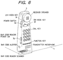
- Fig. 6 there is shown an example of an external view of the portable station 3.
- the portable station radio unit 30 and the bar code reader 31 are integrated in one unit and the bar code reader 31 is located under a casing of the bar code reader, thereby implementing ease of operation.
- another power switch 3b dedicated to the bar code reader 31 is provided.
- the power switch 3b is turned off to save the battery-driven bar code reader when it is not in use.
- a bar code is entered, a reproduced message is immediately outputted.
- the off-hook key 3c is pressed in this state, dialing to a number read from the bar code is automatically performed.
- reference numeral 3d indicates an on-hook key.
- the portable station 3 is provided on the outside thereof with components identified as shown in Fig. 6.
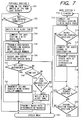
- processing steps 701 through 712 indicate operations of the portable station 3 respectively
- processing steps 714 through 720 indicate operations of the base station 2 respectively
- processing step 713 indicates a speech mode operation different from the recorded message reproducing operations.
- the operations of the portable station 3 will be described.
- the operator of the portable station 3 turns on the bar code power switch 3b and the power switch 3a (step 701) to start bar code reading operation (step 702).
- the reading operation is repeated until a bar code is read correctly (each bar code is attached with a check code at generation of each bar code).
- the operator is notified thereof with an alert tone (step 703).
- the radio path is connected with the base station 2 (step 704).
- a reproduction address information for a message recorded in automatic answering is transmitted to the base station 2 and a calling party telephone number is stored in the control circuit 3015 (step 705).
- the reproduced speech message is transmitted from the base station 2.
- the portable station radio block 30 connects a received speech path to output the decoded speech reproduction (step 706).
- step 707 the operator of the portable station 3 presses the off-hook key (step 707), waits until a predetermined time passes (step 708) or enters the bar code again (step 709).
- step 712 the operator is notified thereof with an alert tone (step 712), upon which the processing goes back to step 705. If a time-out occurs, a request for disconnecting the radio path is transmitted (step 711) and the path with the base station 2 is discarded, upon which the processing goes back to step 702.
- step 710 if the operator of the portable station 3 selects to press the off-hook key 3c within the predetermined time, calling to a telephone number stored in the control circuit 3015 is performed on the radio path in connection (step 710) and the processing moves to the cordless telephone speech mode (step 713).
- the speech mode terminates when the on-hook key 3d is pressed.
- This processing flow makes it unnecessary to redo the setting of the radio path every time a recorded speech message is reproduced, resulting in a prompt speech message reproduction.
- the reproduction can be made simply by entering the bar code again.
- call-back contact for a confirmation call, gratitude call or the like for the recorded speech message can be made only by pressing the off-hook key 3c, thus saving the dialing for a calling operation.
- the base station 2 is in a standby state (step 714).
- the base station receives a connection request from the portable station 3
- the base station sets a radio path for communication data (step 715) and enters a state in which to receive the communication data including the reproduction address of a speech message (step 716).
- the base station Upon reception of the address information, the base station recognizes message reproduction, sets a path for stored speech reproduction listed in Table 3 (step 717), and transmits the speech message again (step 718).
- the base station determines whether to receive calling request (step 719) or receive a disconnection request (step 720). If the base station receives the calling request, the base station enters the speech mode (step 713) and if the base station receives the disconnection request, the base station goes back to the standby state of step 714.
- the present invention solves the above-mentioned intercepting problem, by utilizing a password to enable acquiring of a speech message.
- a facsimile to be sent is highly confidential
- the sending party of such a facsimile document selects a recording mode (hereinafter referred to as a confidential mode) for prohibiting unauthorized parties from accessing the message and instructs a number for specifying the receiving party in a tone signal.
- a confidential mode a recording mode for prohibiting unauthorized parties from accessing the message and instructs a number for specifying the receiving party in a tone signal.
- Such operations are performed (not shown) after the voice contact reservation in step 509 of Fig. 2.
- the receive side of the message prints information in addition to the message recording address information in step 512 in which the bar code is printed.
- the additional information includes a confidential code indicating the confidential mode and the password registered in the base station 2 for the specified destination, which information are printed along with the message recording address information and the like as bar coded data.
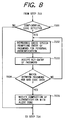
- Fig. 8 shows a part of the operational flow of the reproducing operation of the portable station 3 of this embodiment which operation is inserted between steps 703 and 704 of the flowchart of Fig. 7, the other steps being the same as those of Fig. 7.
- step 702 When the normal entry of the bar code is detected by the portable station 3 (step 702), the operator is notified of the normal entry (step 703), followed by the detection of the confidential code as shown in Fig. 8 (step 7031). If the confidential code is not detected, the processing goes to step 704 in which the reproducing operation of the conventional embodiment is carried out. If the confidential code is detected, a guide speech stored in the portable station 3 is reproduced (step 7032). This guide speech may be "This message is protected: enter your password", for example.
- the guide speech data may be stored in the digital form compressed by the coding algorithm of the speech coder 3019 shown in Fig. 5.
- a portable station radio unit provided with the guide speech reproducing path is indicated by reference numeral 30' in Fig. 9. In Fig. 9, reference numeral 90 indicates a memory for storing the guide speech.
- a switching circuit 91 is controlled by the control circuit 3015 such that the memory 90 is selected at guide speech reproduction and the receive frame processing circuit 3005 is selected at other times.
- step 7033 the operator enters the password in response to the guide speech (step 7033).
- the password from the portable station and the password read from the bar code is compared to determine a match (step 7034). If a match is found, the portable station 3 indicates the completion of the authentication with alert tone (step 7035) to go to the next step of connecting the radio path with the base station 2. If the match is not found, the processing goes back to step 7032.
- the above-mentioned operational flow of the invention prevents any unauthorized person from accessing the messages.
- speech message storage information can be attached in an optically readable form to a received facsimile image when the image is recorded to be outputted.
- Reproduction of a stored message is activated by a simple operation of detecting the attached address information by the optical reading means.
- the speech message returned by the speech data storage unit via the radio path the message can be remotely obtained from the facsimile terminal without locational restrictions. Consequently, the speech message can be reproduced repeatedly with the simple operation and the confidentiality of communication is secured, thereby making the present invention preferable for household application.
Landscapes
- Engineering & Computer Science (AREA)
- Signal Processing (AREA)
- Multimedia (AREA)
- Computer Networks & Wireless Communication (AREA)
- General Engineering & Computer Science (AREA)
- Human Computer Interaction (AREA)
- Telephonic Communication Services (AREA)
- Facsimiles In General (AREA)
- Mobile Radio Communication Systems (AREA)
- Facsimile Transmission Control (AREA)
Applications Claiming Priority (3)
| Application Number | Priority Date | Filing Date | Title |
|---|---|---|---|
| JP6202167A JPH0870366A (ja) | 1994-08-26 | 1994-08-26 | 音声メッセージの記録再生方法及び通信装置 |
| JP202167/94 | 1994-08-26 | ||
| JP20216794 | 1994-08-26 |
Publications (2)
| Publication Number | Publication Date |
|---|---|
| EP0703692A2 true EP0703692A2 (fr) | 1996-03-27 |
| EP0703692A3 EP0703692A3 (fr) | 1999-11-17 |
Family
ID=16453077
Family Applications (1)
| Application Number | Title | Priority Date | Filing Date |
|---|---|---|---|
| EP95113377A Withdrawn EP0703692A3 (fr) | 1994-08-26 | 1995-08-25 | Appareil et méthode d'enregistrement et de reproduction d'un message vocal |
Country Status (3)
| Country | Link |
|---|---|
| US (1) | US5778314A (fr) |
| EP (1) | EP0703692A3 (fr) |
| JP (1) | JPH0870366A (fr) |
Cited By (6)
| Publication number | Priority date | Publication date | Assignee | Title |
|---|---|---|---|---|
| GB2309852A (en) * | 1996-02-02 | 1997-08-06 | Sagem | Voice-annotated FAX |
| FR2770723A1 (fr) * | 1997-10-30 | 1999-05-07 | Sagem | Ensemble d'analyse d'image d'un telephone portable et d'un dispositif de balayage d'analyse d'image relie au telephone, le telephone et le dispositif |
| EP0932292A1 (fr) * | 1998-01-23 | 1999-07-28 | Sagem Sa | Réseau local de téléphonie sans fil et base et terminal mobile de communication d'un tel réseau |
| DE102004061725A1 (de) * | 2004-12-19 | 2006-06-29 | Gbs Holding Gmbh | Sprachaufzeichnungsgerät und Verfahren zur Verarbeitung von Sprachaufzeichnungen |
| EP2352273A1 (fr) * | 2005-05-19 | 2011-08-03 | YOSHIDA, Kenji | Système de messagerie vocale avec enrégistreur vocal portable |
| CN102972014A (zh) * | 2010-07-13 | 2013-03-13 | Bsh博世和西门子家用电器有限公司 | 移动电话读取处于故障的家用器具上的条形码并且自动与客户服务连接的方法 |
Families Citing this family (16)
| Publication number | Priority date | Publication date | Assignee | Title |
|---|---|---|---|---|
| US6424830B1 (en) * | 1994-07-26 | 2002-07-23 | Telxon Corporation | Portable data collection network with telephone and voice mail capability |
| US6366771B1 (en) * | 1995-06-21 | 2002-04-02 | Arron S. Angle | Wireless communication network having voice and data communication capability |
| KR0168793B1 (ko) * | 1996-03-30 | 1999-02-01 | 김광호 | 기지국의 안내 방송장치 및 방법 |
| US6212401B1 (en) * | 1996-12-24 | 2001-04-03 | Intermec Corporation | Data acquisition using telephone connection |
| FR2762952A1 (fr) * | 1997-04-30 | 1998-11-06 | Philips Electronics Nv | Appareil telephonique comportant une station de base et au moins un dispositif d'abonne, dispositif d'abonne pour un tel appareil et procede mis en oeuvre dans un tel appareil |
| US6816723B1 (en) * | 1997-06-12 | 2004-11-09 | Legerity, Inc. | Telephony device with integrated messaging |
| US6049604A (en) * | 1997-06-23 | 2000-04-11 | Winbond Electronics Corporation | Telephone dialer having at least one speech synthesizer processor |
| JP3235654B2 (ja) * | 1997-11-18 | 2001-12-04 | 日本電気株式会社 | 無線電話装置 |
| US6240299B1 (en) * | 1998-02-20 | 2001-05-29 | Conexant Systems, Inc. | Cellular radiotelephone having answering machine/voice memo capability with parameter-based speech compression and decompression |
| US6546241B2 (en) * | 1999-11-02 | 2003-04-08 | Agere Systems Inc. | Handset access of message in digital cordless telephone |
| JP4304558B2 (ja) * | 1999-11-14 | 2009-07-29 | ソニー株式会社 | 携帯機器 |
| US6594503B1 (en) * | 2000-02-02 | 2003-07-15 | Motorola, Inc. | Communication device with dial function using optical character recognition, and method |
| US20020098865A1 (en) * | 2000-12-04 | 2002-07-25 | Nortel Networks Limited | Method and system to transition from a facsimile communications session to a voice communications session |
| KR100617824B1 (ko) * | 2004-01-16 | 2006-08-28 | 삼성전자주식회사 | 이동통신 단말기 및 그의 자동응답 수행방법 |
| JP2006327017A (ja) * | 2005-05-26 | 2006-12-07 | Citizen Watch Co Ltd | 印刷装置及び条件設定方法 |
| JP5170090B2 (ja) * | 2007-05-31 | 2013-03-27 | 富士通株式会社 | データ連携システム、データ連携方法およびデータ連携プログラム |
Citations (4)
| Publication number | Priority date | Publication date | Assignee | Title |
|---|---|---|---|---|
| JPH05227347A (ja) | 1992-02-13 | 1993-09-03 | Ricoh Co Ltd | ファクシミリ伝送方法および情報記録装置 |
| JPH05300294A (ja) | 1992-04-21 | 1993-11-12 | Mitsubishi Electric Corp | ファクシミリ装置 |
| JPH05300293A (ja) | 1992-04-17 | 1993-11-12 | Toshiba Corp | 音声格納機能付ファクシミリ装置 |
| JPH05300359A (ja) | 1992-04-21 | 1993-11-12 | Fujitsu General Ltd | ファクシミリ装置 |
Family Cites Families (15)
| Publication number | Priority date | Publication date | Assignee | Title |
|---|---|---|---|---|
| US4304968A (en) * | 1979-09-24 | 1981-12-08 | Klausner Industries | Telephone electronic answering device |
| GB8500071D0 (en) * | 1985-01-03 | 1985-02-13 | Varley T | Telephone equipment |
| DE3878653D1 (de) * | 1987-09-14 | 1993-04-01 | Autophon Ascom Ag | Telefonstation mit einem teilnehmerverzeichnis. |
| US4897865A (en) * | 1988-04-29 | 1990-01-30 | Epic Data, Inc. | Telephone data collection device |
| DE3814728A1 (de) * | 1988-04-30 | 1989-11-09 | Telefonbau & Normalzeit Gmbh | Drahtloses fernsprechsystem |
| US5459584A (en) * | 1988-09-22 | 1995-10-17 | Audiofax, Inc. | Facsimile telecommunications system and method |
| US4975948A (en) * | 1989-10-13 | 1990-12-04 | Andresen Dennis R | Rapid dialing method for telecommunications |
| JP2765161B2 (ja) * | 1990-02-23 | 1998-06-11 | ソニー株式会社 | コードレス電話 |
| JP2523926B2 (ja) * | 1990-04-04 | 1996-08-14 | 松下電器産業株式会社 | 複合電話機 |
| JP2610691B2 (ja) * | 1990-04-06 | 1997-05-14 | シャープ株式会社 | 通信装置 |
| US5426511A (en) * | 1990-09-14 | 1995-06-20 | Kabushiki Kaisha Toshiba | Facsimile system with base unit connected to wire network and in communication with multiple extensions sets by wire or radio transmission |
| US5144654A (en) * | 1991-03-22 | 1992-09-01 | Kelley James T | Automatic telephone dialer system with printed storage |
| US5509050A (en) * | 1991-04-16 | 1996-04-16 | Quadphase Corporation | Facsimile radio communication system having multiple data speeds |
| US5479411A (en) * | 1993-03-10 | 1995-12-26 | At&T Corp. | Multi-media integrated message arrangement |
| US5426594A (en) * | 1993-04-02 | 1995-06-20 | Motorola, Inc. | Electronic greeting card store and communication system |
-
1994
- 1994-08-26 JP JP6202167A patent/JPH0870366A/ja active Pending
-
1995
- 1995-08-24 US US08/518,975 patent/US5778314A/en not_active Expired - Fee Related
- 1995-08-25 EP EP95113377A patent/EP0703692A3/fr not_active Withdrawn
Patent Citations (4)
| Publication number | Priority date | Publication date | Assignee | Title |
|---|---|---|---|---|
| JPH05227347A (ja) | 1992-02-13 | 1993-09-03 | Ricoh Co Ltd | ファクシミリ伝送方法および情報記録装置 |
| JPH05300293A (ja) | 1992-04-17 | 1993-11-12 | Toshiba Corp | 音声格納機能付ファクシミリ装置 |
| JPH05300294A (ja) | 1992-04-21 | 1993-11-12 | Mitsubishi Electric Corp | ファクシミリ装置 |
| JPH05300359A (ja) | 1992-04-21 | 1993-11-12 | Fujitsu General Ltd | ファクシミリ装置 |
Cited By (8)
| Publication number | Priority date | Publication date | Assignee | Title |
|---|---|---|---|---|
| GB2309852A (en) * | 1996-02-02 | 1997-08-06 | Sagem | Voice-annotated FAX |
| GB2309852B (en) * | 1996-02-02 | 1999-11-10 | Sagem | A telephony device with voice annotation |
| FR2770723A1 (fr) * | 1997-10-30 | 1999-05-07 | Sagem | Ensemble d'analyse d'image d'un telephone portable et d'un dispositif de balayage d'analyse d'image relie au telephone, le telephone et le dispositif |
| EP0932292A1 (fr) * | 1998-01-23 | 1999-07-28 | Sagem Sa | Réseau local de téléphonie sans fil et base et terminal mobile de communication d'un tel réseau |
| FR2774249A1 (fr) * | 1998-01-23 | 1999-07-30 | Sagem | Reseau local de telephonie sans fil et base et terminal mobile de communication d'un tel reseau |
| DE102004061725A1 (de) * | 2004-12-19 | 2006-06-29 | Gbs Holding Gmbh | Sprachaufzeichnungsgerät und Verfahren zur Verarbeitung von Sprachaufzeichnungen |
| EP2352273A1 (fr) * | 2005-05-19 | 2011-08-03 | YOSHIDA, Kenji | Système de messagerie vocale avec enrégistreur vocal portable |
| CN102972014A (zh) * | 2010-07-13 | 2013-03-13 | Bsh博世和西门子家用电器有限公司 | 移动电话读取处于故障的家用器具上的条形码并且自动与客户服务连接的方法 |
Also Published As
| Publication number | Publication date |
|---|---|
| EP0703692A3 (fr) | 1999-11-17 |
| JPH0870366A (ja) | 1996-03-12 |
| US5778314A (en) | 1998-07-07 |
Similar Documents
| Publication | Publication Date | Title |
|---|---|---|
| US5778314A (en) | Speech message recording and reproducing method and apparatus | |
| EP0614305B1 (fr) | Dispositif de communication son et image simultanée | |
| EP0473162B1 (fr) | Dispositif de fac-similé, capable d'un traitement désiré dépendant du numéro de l'appareil qui appelle | |
| US5805678A (en) | Cordless subunit facsimile system | |
| US6463129B1 (en) | Call screening method of a facsimile system having a stationary main unit connected to a telephone network and a cordless portable unit | |
| JP2862191B2 (ja) | 記録装置 | |
| JPH0195656A (ja) | ファクシミリ機能を備えた留守番電話装置 | |
| JP3173270B2 (ja) | ファクシミリ装置 | |
| JPH0766912A (ja) | ファクシミリ装置の制御方式 | |
| JP2606696B2 (ja) | 有線・無線両用フアクシミリ装置 | |
| JPS6167364A (ja) | フアクシミリ装置 | |
| KR100229020B1 (ko) | 휴대장치로 무선전화 겸용 팩시밀리장치의 동작상태 음성 알림방법 | |
| US6614547B1 (en) | Cordless facsimile system with telephone answering function and method for controlling the same | |
| JPH01191560A (ja) | ファクシミリ装置 | |
| KR100233723B1 (ko) | 팩시밀리장치에서 휴대장치의 호출에 응답한 동작상태 알림방법 | |
| JPS62231558A (ja) | 電話機内蔵フアクシミリ | |
| JPH03227148A (ja) | 移動体におけるファクシミリ通信方法 | |
| JPH07235978A (ja) | メモリ発呼式電話装置 | |
| JPH0787232A (ja) | コードレスファクシミリ装置 | |
| JPH0271666A (ja) | ファクシミリ装置 | |
| JPH04356864A (ja) | ファクシミリ装置 | |
| JPH04103770U (ja) | 電話回線端末装置 | |
| JPS62195973A (ja) | フアクシミリ装置における送信報知方式 | |
| JPH05219295A (ja) | ファクシミリ装置 | |
| JPH0720065B2 (ja) | デ−タ通信装置 |
Legal Events
| Date | Code | Title | Description |
|---|---|---|---|
| PUAI | Public reference made under article 153(3) epc to a published international application that has entered the european phase |
Free format text: ORIGINAL CODE: 0009012 |
|
| 17P | Request for examination filed |
Effective date: 19950825 |
|
| AK | Designated contracting states |
Kind code of ref document: A2 Designated state(s): DE FR GB |
|
| PUAL | Search report despatched |
Free format text: ORIGINAL CODE: 0009013 |
|
| AK | Designated contracting states |
Kind code of ref document: A3 Designated state(s): DE FR GB |
|
| RIC1 | Information provided on ipc code assigned before grant |
Free format text: 6H 04M 1/72 A, 6H 04N 1/00 B, 6H 04N 1/32 B, 6H 04M 1/65 B |
|
| STAA | Information on the status of an ep patent application or granted ep patent |
Free format text: STATUS: THE APPLICATION IS DEEMED TO BE WITHDRAWN |
|
| 18D | Application deemed to be withdrawn |
Effective date: 20000518 |