EP0703861B1 - Vorrichtung zum waschen und trocknen von druckplatten - Google Patents
Vorrichtung zum waschen und trocknen von druckplatten Download PDFInfo
- Publication number
- EP0703861B1 EP0703861B1 EP94919638A EP94919638A EP0703861B1 EP 0703861 B1 EP0703861 B1 EP 0703861B1 EP 94919638 A EP94919638 A EP 94919638A EP 94919638 A EP94919638 A EP 94919638A EP 0703861 B1 EP0703861 B1 EP 0703861B1
- Authority
- EP
- European Patent Office
- Prior art keywords
- rolls
- printing plates
- roll
- washing
- gap
- Prior art date
- Legal status (The legal status is an assumption and is not a legal conclusion. Google has not performed a legal analysis and makes no representation as to the accuracy of the status listed.)
- Expired - Lifetime
Links
- 238000007639 printing Methods 0.000 title claims abstract description 40
- 238000005406 washing Methods 0.000 title claims abstract description 16
- 238000001035 drying Methods 0.000 title claims abstract description 13
- 239000007788 liquid Substances 0.000 claims description 21
- 238000004321 preservation Methods 0.000 claims description 3
- 239000003755 preservative agent Substances 0.000 claims 1
- 230000002335 preservative effect Effects 0.000 claims 1
- 238000007664 blowing Methods 0.000 description 6
- 238000005452 bending Methods 0.000 description 2
- 238000011161 development Methods 0.000 description 2
- 230000018109 developmental process Effects 0.000 description 2
- 238000000034 method Methods 0.000 description 2
- 238000007645 offset printing Methods 0.000 description 2
- CYJRNFFLTBEQSQ-UHFFFAOYSA-N 8-(3-methyl-1-benzothiophen-5-yl)-N-(4-methylsulfonylpyridin-3-yl)quinoxalin-6-amine Chemical compound CS(=O)(=O)C1=C(C=NC=C1)NC=1C=C2N=CC=NC2=C(C=1)C=1C=CC2=C(C(=CS2)C)C=1 CYJRNFFLTBEQSQ-UHFFFAOYSA-N 0.000 description 1
- 206010013786 Dry skin Diseases 0.000 description 1
- 238000005253 cladding Methods 0.000 description 1
- 230000003111 delayed effect Effects 0.000 description 1
- 230000001419 dependent effect Effects 0.000 description 1
- 239000008237 rinsing water Substances 0.000 description 1
- 238000004904 shortening Methods 0.000 description 1
- 239000007921 spray Substances 0.000 description 1
- 238000005507 spraying Methods 0.000 description 1
Images


Classifications
-
- B—PERFORMING OPERATIONS; TRANSPORTING
- B41—PRINTING; LINING MACHINES; TYPEWRITERS; STAMPS
- B41F—PRINTING MACHINES OR PRESSES
- B41F35/00—Cleaning arrangements or devices
- B41F35/001—Devices for cleaning parts removed from the printing machines
Definitions
- the invention relates to a device for washing and drying plates with the features specified in the preamble of claim 1.
- Such devices are used to clean offset printing plates, which are removed from the printing press after the printing process, of ink in several stations, to keep the capillaries free and to preserve or to gum and dry the surface.
- the goal is to get a perfectly cleaned and preserved offset printing plate To be able to use the archive in order to be able to take a perfect printing plate into the printing press for repeat jobs.
- the known device has in succession a washing station for washing the ink from the surface of the printing plate, a rinsing station for rinsing the washing liquid and a station for preserving or gumming the printing surface of the printing plates, and a drying device consisting of rollers for squeezing the liquid from the printing plate and / or blowing nozzles that are directed against the pressure plate.
- the printing plates are guided horizontally through the station with the aid of pairs of rollers.
- the nips are at the same height and the printing plates are guided and conveyed by clamping in the nip, for which purpose at least one roller is driven per pair of rollers.
- the known device works quite well with flat pressure plates.
- a bend is often formed at the edge of the printing plate, and the larger it is, the more difficult it is to convey the printing plate between the pairs of rollers.
- the object of the present invention is to create a washing and drying device which is also suitable for folded printing plates.
- the invention provides for an unobstructed passage of the folded edge strip of a printing plate through all stations of the device either above or below the nip.
- the obstacle-free passage is limited by mutually aligned longitudinal guide devices in all stations of the device. If a printing plate with a folded edge is inserted into the device in such a way that the folded edge runs in the conveying direction so that it lies in the passage adjacent to the nip and the device can pass through unhindered, then the pairs of rolls only grip the flat part of the printing plates and become not hindered by the folded edge.
- the longitudinal guide devices ensure the bevelled edge, which laterally limit the obstacle-free passage through the device.
- the guide devices are preferably located below the nip; the printing plate can then be conveyed through the device with the printing side facing upwards and washed from above. Since the folded edge points downwards, there is no blind spot on the top in which washing or rinsing liquid could accumulate, rather it runs off over the folded edge, which also forms a drip edge.
- the guide devices are preferably formed by providing a circumferential recess in each roller pair in the jacket of the lower or upper rollers, into which the folded edge of the pressure plate can protrude.
- the boundaries of the recess are then also the longitudinal guide devices. If the folded edge comes into contact with the boundary of the longitudinal guide device, this can practically not result in the plate on this edge being delayed by friction on the longitudinal guide; rather, low-friction straight-line travel is ensured because the longitudinal guide follows the rotation of the roller.
- the pressure plates with their folded edge into the device such that the bent edge protrudes beyond the end of the roll shell of the lower roll in the direction of the bearing journal of the roll.
- the upper roller jacket is longer and protrudes beyond the folded edge of the plate to ensure that the liquid is squeezed off the entire surface of the plate.
- the end of the jacket of the roller serves as a guide device on one side of the folded edge of the pressure plate, and as a guide on the other side of the folded edge, a separate guide part fixed to the frame is then provided, in particular a guide bar parallel to the conveying direction.
- the guiding devices are preferably continued in the inlet table of the device, so that the pressure plates with their beveled edges can be placed and threaded in the desired alignment.
- the edge of the table could be used as part of the guide device and a bar arranged parallel to it, which together with the edge of the inlet table forms a guide device in alignment with the passage through the device.
- the infeed table is made a little wider and a guide groove is provided in it.
- Appropriate training could also be provided at the outlet table, but is not necessary there. Only care must be taken there that the folded edge strip of the printing plates can run out unhindered, e.g. simply by shortening the discharge table on one side so that the folded edge of the plate runs next to the discharge table when the edge points downwards.
- the rollers can grasp the flat area of the printing plates unhindered and squeeze liquid located thereon, in the flat area of the printing plates there can be no significant carryover of liquid from one station to the next station.
- This is usually done by applying the preserving or gumming liquid to the pressure side of the printing plate with the upper roller of a pair of rollers in the preserving or gumming station, specifically on the inlet side of the nip.
- passage of the preservation or gumming liquid onto the outlet side of the roller gap is favored.
- a particular advantage of the invention is that they do not only process weakly folded printing plates can, but also printing plates that are folded over a large angle, which can even be more than 90 °, for example 110 °.
- the device has in succession an inlet table 1, a washing station 2, a rinsing station 3, a gumming station 4, a drying device 5 and an outlet table 6.
- a washing station 2 there is a trough 7 for collecting the washing liquid, in the rinsing station 3 a tub 8 for collecting the rinsing water, in the gumming station 4 a tub 9 for collecting the gumming liquid. If necessary, further washing and rinsing stations could also be provided.
- each station there are at least two pairs of rollers consisting of top roller 10 and bottom roller 11, namely one pair of rollers on the input side of the station and another pair of rollers on the output side of the station.
- the roller pairs 10, 11 have the task of conveying the printing plates, which is why at least one roller can be driven in each roller pair. They also have the task of guiding the printing plates, which is why the sequence of the nips lies in a common alignment and the lower roller 11 has a recess 12 near its one end for receiving a folded edge of the printing plates.
- the recesses 12 of the lower rollers are also in common alignment.
- the pair of rollers on the exit side of each station also has the task of squeezing the liquid off the pressure plate.
- the rollers therefore have, for example, a jacket made of rubber, which at the same time produces the frictional connection with them necessary for conveying the printing plates.
- the top rollers 10 are pressed against the bottom rollers.
- the top rollers can be resilient, in such a way that they can be raised against spring force.
- the pressure plate 13 with its folded edge 14 into the guide groove 17 it is automatically fed to the roller pairs in the correct position, so that the bent edge 14 lies in the recess 12 of the lower roller 11 or next to the end of the lower roller shell and, moreover, the plane
- the area of the pressure plate 13 can be gripped freely by the top roller 10 and the bottom roller 11 and the top pressure side of the pressure plate 13 can be pre-dried over the entire surface by squeezing off the liquid thereon (see FIG. 3).
- the last pair of rollers in the gumming station 4 is used to apply a gum liquid to the top of the pressure plate 13.
- a spray tube 18 is assigned to the top roller 10 on the inlet side of the nip, which extends parallel to the top roller 10 and out a sequence of nozzle openings 19 spraying rubber liquid onto a distributor plate 20, which the upper roller 10 is resilient is applied and the gumming liquid is distributed as a film 21 on the top roller, which it applies in the nip to the top of the pressure plate 13.
- a blowing air nozzle 22 is arranged above the nip and runs parallel to the upper roller 10 and has nozzle openings 23, which are distributed over its length and directed against the nip, from which air is blown into the outlet side of the nip in order to prevent gumming liquid from runs through the nip.
- two further blowing air nozzles 24 and 25 are provided, one above and one below the pressure plate 13, which act on the pressure plate 13 on both sides with cold air or, if necessary, with hot air in order to finally dry it.
- the dried pressure plates 13 run on the outlet table 6, which is shortened on the left-hand side when looking in the conveying direction 26 to such an extent that the lateral edge 27 of the table plate is no longer in alignment with the recess 12 in the lower roller, so that the folded edge 14 the pressure plate runs along the edge 27.
Landscapes
- Inking, Control Or Cleaning Of Printing Machines (AREA)
- Drying Of Solid Materials (AREA)
- Cleaning In General (AREA)
Abstract
Description
- Die Erfindung geht aus von einer Vorrichtung zum Waschen und Trocknen von Platten mit den im Oberbegriff des Anspruchs 1 angegebenen Merkmalen. Solche Vorrichtungen dienen dazu, Offset-Druckplatten, welche nach dem Druckvorgang aus der Druckmaschine entnommen werden, in mehreren Stationen von Farbe zu reinigen, die Kapillaren freizuhalten und die Oberfläche zu konservieren bzw. zu gummieren und zu trocknen. Das Ziel ist, eine einwandfrei gereinigte und konservierte Offset-Druckplatte ins Archiv nehmen zu können, um bei Wiederholungsaufträgen eine einwandfreie Druckplatte in die Druckmaschine nehmen zu können.
- Die bekannte Vorrichtung hat aufeinanderfolgend eine Waschstation zum Abwaschen der Farbe von der Oberfläche der Druckplatte, eine Spülstation zum Abspülen der Waschflüssigkeit und eine Station zum Konservieren bzw. Gummieren der Druckoberfläche der Druckplatten, sowie eine Trocknungseinrichtung bestehend aus Walzen zum Abquetschen der Flüssigkeit von der Druckplatte und/oder von Blasdüsen, die gegen die Druckplatte gerichtet sind.
- Die Druckplatten werden mit Hilfe von Walzenpaaren waagerecht durch die Station geführt. Die Walzenspalte liegen auf gleicher Höhe und die Druckplatten werden durch Klemmung im Walzenspalt geführt und gefördert, wozu wenigstens eine Walze pro Walzenpaar angetrieben ist.
- Die bekannte Vorrichtung funktioniert ganz gut mit ebenen Druckplatten. Beim Einspannen von Druckplatten in eine Druckmaschine entsteht jedoch gern eine Abkantung am Rand der Druckplatte, und je größer sie ist, desto schwieriger ist es, die Druckplatte zwischen den Walzenpaaren hindurchzufördern. Es kommt zu erhöhtem Verschleiß an den Walzen und zur Verschleppung von Flüssigkeit aus einer Station in die folgende Station, weil die Walzenpaare infolge der Abkantung der Druckplatte die Flüssigkeit von dieser nicht mehr hinreichend abquetschen können.
- Der vorliegenden Erfindung liegt die Aufgabe zugrunde, eine auch für abgekantete Druckplatte gut geeignete Wasch- und Trockenvorrichtung zu schaffen.
- Diese Aufgabe wird gelöst durch eine Vorrichtung mit den im Anspruch 1 angegebenen Merkmalen. Vorteilhafte Weiterbildungen der Erfindung sind Gegenstand der abhängigen Ansprüche.
- Die Erfindung sorgt für einen hindernisfreien Durchgang des abgekanteten Randstreifens einer Druckplatte durch sämtliche Stationen der Vorrichtung entweder oberhalb oder unterhalb des Walzenspaltes. Dabei wird der hindernisfreie Durchgang begrenzt durch miteinander fluchtende Längsführungseinrichtungen in allen Stationen der Vorrichtung. Wird eine Druckplatte mit abgekantetem Rand so in die Vorrichtung eingeführt, dass der abgekantete Rand in Förderrichtung verläuft, so dass er in dem an den Walzenspalt angrenzenden Durchgang liegt und die Vorrichtung ungehindert durchlaufen kann, dann ergreifen die Walzenpaare lediglich den ebenen Teil der Druckplatten und werden darin durch den abgekanteten Rand nicht behindert . Dafür, dass der ebene Bereich der Druckplatten nicht quer zur Förderrichtung aus dem Walzenspalt herausdriftet, sorgen die Längsführungseinrichtungen für den abgekanteten Rand, welche den hindernisfreien Durchgang durch die Vorrichtung seitlich begrenzen.
- Vorzugsweise liegen die Führungseinrichtungen unterhalb des Walzenspaltes; dann kann die Druckplatte mit der Druckseite nach oben weisend durch die Vorrichtung gefördert und von oben gewaschen werden. Da der abgekantete Rand nach unten weist, gibt es auf der Oberseite keinen toten Winkel, in welchem sich Wasch- oder Spülflüssigkeit ansammeln könnte, sie läuft vielmehr über den abgekanteten Rand ab, der zugleich eine Abtropfkante bildet.
- Vorzugsweise werden die Führungseinrichtungen dadurch gebildet, dass man im Mantel der unteren bzw. der oberen Walzen in einem jeden Walzenpaar einen umlaufenden Einstich vorsieht, in welchen der abgekantete Rand der Druckplatte hineinragen kann. Die Begrenzungen des Einstichs sind dann zugleich die Längsführungseinrichtungen. Kommt der abgekantete Rand mit der Begrenzung der Längsführungseinrichtung in Berührung, dann kann das praktisch nicht dazu führen, dass die Platte an diesem Rand durch Reibung an der Längsführung verzögert wird, vielmehr ist ein reibungsarmer Geradeauslauf gewährleistet, weil die Längsführung durch die Walzendrehung mitläuft.
- Es wäre aber auch möglich, die Druckplatten mit ihrem abgekanteten Rand so in die Vorrichtung einzuführen, dass der abgekantete Rand über das Ende des Walzenmantels der unteren Walze hinausragt in Richtung auf den Lagerzapfen der Walze. Der obere Walzenmantel ist länger und ragt über den abgekanteten Plattenrand hinaus, um das Abquetschen der Flüssigkeit von der gesamten Plattenoberfläche zu sichern. In diesem Fall dient das Ende des Mantels der Walze als Führungseinrichtung auf der einen Seite des abgekanteten Randes der Druckplatte, und als Führung auf der anderen Seite des abgekanteten Randes sieht man dann ein gesondertes, gestellfestes Führungsteil vor, insbesondere eine zur Förderrichtung parallele Führungsleiste.
- Vorzugsweise sind die Führungseinrichtungen in den Einlauftisch der Vorrichtung fortgesetzt, damit man die Druckplatten mit ihrem abgekanteten Rand in der gewünschten Flucht aufgeben und einfädeln kann. Zu diesem Zweck könnte man den Rand des Tisches als Teil der Führungseinrichtung verwenden und parallel zu ihm eine Leiste anordnen, welche zusammen mit dem Rand des Einlauftisches eine Führungseinrichtung in der Flucht des Durchgangs durch die Vorrichtung bildet. Vorzugsweise macht man den Einlauftisch aber etwas breiter und sieht in ihm eine Führungsnut vor. Eine entsprechende Ausbildung könnte man am Auslauftisch auch vorsehen, ist dort aber nicht nötig. Dort muss lediglich Sorge dafür getragen werden, dass der abgekantete Randstreifen der Druckplatten ungehindert auslaufen kann, z.B. einfach dadurch, dass man, wenn der Rand nach unten weist, den Auslauftisch einseitig soweit verkürzt, dass der abgekantete Rand der Platte neben dem Auslauftisch läuft.
- Da bei der erfindungsgemässen Vorrichtung die Walzen den ebenen Bereich der Druckplatten ungehindert ergreifen und darauf befindliche Flüssigkeit abquetschen können, kann es im ebenen Bereich der Druckplatten zu keiner nennenswerten Verschleppung von Flüssigkeit aus einer Station in die folgende Station kommen. Ein gewisses Problem kann es allerdings geben mit der streifenfreien Trocknung der Druckplatten im Bereich des abgekanteten Randes nach dem Konservieren bzw. Gummieren. Das geschieht üblicherweise dadurch, dass man mit der oberen Walze eines Walzenpaares in der Konservier- bzw. Gummierstation die Konservierungs- bzw. Gummierflüssigkeit auf die Druckseite der Druckplatte aufträgt, und zwar auf der Einlaufseite des Walzenspaltes. Infolge der Abkantung der Druckplatte und ihrer Führung im Einstich der Walze wird jedoch ein Durchlaufen der Konservierungs- bzw. Gummierungsflüssigkeit auf die Auslaufseite des Walzenspaltes begünstigt. Dem begegnet man in Weiterbildung der Erfindung mit Vorteil dadurch, dass man parallel zu der Walze, mit welcher man die Gummierungs- bzw. Konservierungsflüssigkeit aufträgt, eine Luftblasdüse anordnet, welche gegen die Auslaufseite des Walzenspaltes gerichtet ist und dadurch einem Durchlaufen der Konservierungs- bzw. Gummierungsflüssigkeit entgegenwirkt, was wiederum eine einwandfreie, streifenfreie Trocknung der Druckplatte begünstigt.
- Ein besonderer Vorteil der Erfindung ist darin zu sehen, dass sie nicht nur schwach abgekantete Druckplatten bearbeiten kann, sondern auch Druckplatten, die um einen großen Winkel abgekantet sind, der sogar mehr als 90°, z.B. 110°, betragen kann.
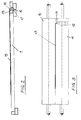
- Ein Ausführungsbeispiel der Erfindung ist in den beigefügten schematischen Zeichnungen dargestellt.
- Figur 1
- zeigt die für das Verständnis der Erfindung wesentlichen Elemente einer Vorrichtung zum Waschen und Trocknen von Druckplatten in einer Schrägansicht ohne Gestell und Verkleidung,
- Figur 2
- zeigt als Detail einen Querschnitt durch den Einlauftisch der Vorrichtung,
- Figur 3
- zeigt die Ansicht eines Walzenpaares mit einer im Walzenspalt eingeklemmten Druckplatte, und
- Figur 4
- zeigt als Detail einen Längsschnitt durch das letzte Walzenpaar in der Gummierstation der Vorrichtung mit anschließender Trocknungseinrichtung.
- Die Vorrichtung hat aufeinanderfolgend einen Einlauftisch 1, eine Waschstation 2, eine Spülstation 3, eine Gummierungsstation 4, eine Trocknungseinrichtung 5 und einen Auslauftisch 6. In der Waschstation 2 befindet sich eine Wanne 7 zum Auffangen der Waschflüssigkeit, in der Spülstation 3 eine Wanne 8 zum Auffangen des Spülwasser, in der Gummierungsstation 4 eine Wanne 9 zum Auffangen der Gummierungsflüssigkeit. Falls erforderlich, könnten auch weitere Wasch- und Spülstationen vorgesehen sein.
- In jeder Station befinden sich wenigstens zwei Walzenpaare bestehend aus Oberwalze 10 und Unterwalze 11, und zwar ein Walzenpaar an der Eingangsseite der Station und ein weiteres Walzenpaar an der Ausgangsseite der Station. Die Walzenpaare 10, 11 haben die Aufgabe, die Druckplatten zu fördern, weshalb wenigstens eine Walze in jedem Walzenpaar antreibbar ist. Sie haben ferner die Aufgabe, die Druckplatten zu führen, weshalb die Folge der Walzenspalte in einer gemeinsamen Flucht liegt und die Unterwalze 11 nahe ihrem einen Ende einen Einstich 12 hat zur Aufnahme eines abgekanteten Randes der Druckplatten. Die Einstiche 12 der Unterwalzen liegen ebenfalls in einer gemeinsamen Flucht. Das Walzenpaar an der Ausgangsseite einer jeden Station hat darüberhinaus die Aufgabe, die Flüssigkeit von der Druckplatte abzuquetschen. Die Walzen haben deshalb z.B. einen Mantel aus Gummi, welcher gleichzeitig den für das Fördern der Druckplatten erforderlichen Reibschluß mit diesen herstellt. Dazu werden die Oberwalzen 10 gegen die Unterwalzen gedrückt. Zu diesem Zweck können die Oberwalzen federnd gelagert sein, und zwar in der Weise, dass sie gegen Federkraft angehoben werden können.
- Damit Druckplatten 13 mit abgekantentem Rand 14 (siehe Figur 2) in der richtigen Orientierung in die Vorrichtung eingeführt werden können, so dass der abgekantete Rand 14 in den Einstichen 12 der Unterwalzen 11 oder neben dem Ende des unteren Walzenmantels läuft, ist zwischen dem einen seitlichen Rand 15 der Tischplatte und einer parallel dazu angeordneten Führungsleiste 16 eine Führungsnut 17 gebildet, welche in der Flucht der Einstiche 12 liegt.
- Legt man die Druckplatte 13 mit ihrem abgekanteten Rand 14 in die Führungsnut 17 ein, so wird sie automatisch lagerichtig den Walzenpaaren zugeführt, so dass der abgekantete Rand 14 im Einstich 12 der Unterwalze 11 oder neben dem Ende des unteren Walzenmantels liegt und im übrigen der ebene Bereich der Druckplatte 13 ungehindert von Oberwalze 10 und Unterwalze 11 ergriffen und die obenliegende Druckseite der Druckplatte 13 auf voller Fläche durch Abquetschen der darauf befindlichen Flüssigkeit vorgetrocknet werden kann (siehe Figur 3).
- Wie Figur 4 zeigt, dient das letzte Walzenpaar in der Gummierungsstation 4 zum Auftragen einer Gummierflüssigkeit auf die Oberseite der Druckplatte 13. Zu diesem Zweck ist der Oberwalze 10 auf der Einlaufseite des Walzenspalts ein Sprührohr 18 zugeordnet, welches sich parallel zur Oberwalze 10 erstreckt und aus einer Folge von Düsenöffnungen 19 Gummierflüssigkeit auf ein Verteilerblech 20 sprüht, welches der Oberwalze 10 federnd anliegt und die Gummierungsflüssigkeit als Film 21 auf der Oberwalze verteilt, welche sie im Walzenspalt auf die Oberseite der Druckplatte 13 aufträgt. Auf der Ausgangseite des Walzenspaltes ist oberhalb des Walzenspaltes eine parallel zur Oberwalze 10 verlaufende Blasluftdüse 22 angeordnet, welche über ihre Länge verteilt gegen den Walzspalt gerichtete Düsenöffnungen 23 hat, aus denen Luft in die Ausgangsseite des Walzenspaltes geblasen wird, um zu verhindern, dass Gummierungsflüssigkeit durch den Walzenspalt hindurchläuft. In einigem Abstand von der Blasluftdüse 22 sind zwei weitere Blasluftdüsen 24 und 25 vorgesehen, eine oberhalb und eine unterhalb der Druckplatte 13, welche die Druckplatte 13 beidseitig mit Kaltluft oder erforderlichenfalls mit Warmluft beaufschlagen, um sie abschließend zu trocknen.
- Die getrockneten Druckplatten 13 laufen auf den Auslauftisch 6, welcher auf der bei Blick in Förderrichtung 26 linken Seite soweit verkürzt ist, dass der seitliche Rand 27 der Tischplatte nicht mehr in der Flucht des Einstichs 12 in der Unterwalze liegt, so dass der abgekantete Rand 14 der Druckplatte neben dem Rand 27 läuft.
Claims (7)
- Vorrichtung zum Waschen und Trocknen von Druckplatten (13)mit einem Einlauftisch (1),mit einer daran anschließenden Reihe von Stationen (2, 3, 4, 5) zum Waschen, zum Spülen, zum Konservieren bzw. Gummieren und zum Trocknen,mit in den verschiedenen Stationen mit waagerechter Drehachse angeordneten Walzenpaaren (10, 11), deren Walzenspalt in Höhe des Einlauftisches (1) liegt, wobei wenigstens eine Walze pro Walzenpaar (10, 11) antreibbar ist, um die Druckplatten (13) im Eingriff mit den Walzen (10, 11) durch die Walzenspalte hindurch zu fördern,und mit einem Auslauftisch (6),
dadurch gekennzeichnet, dass in allen Stationen (2, 3, 4, 5) in einer gemeinsamen, mit der Förderrichtung (26) der Walzenpaare (10, 11) zusammenfallenden Flucht Längsführungseinrichtungen (12) vorgesehen sind, welche sämtlich entweder oberhalb oder unterhalb des Walzenspalts liegen und angrenzend an den Walzenspalt einen hindernisfreien Durchgang durch sämtliche Stationen (2, 3, 4, 5) begrenzen. - Vorrichtung nach Anspruch 1, dadurch gekennzeichnet, dass die Längsführungseinrichtungen (12) unterhalb des Walzenspalts liegen.
- Vorrichtung nach Anspruch 1, dadurch gekennzeichnet, dass die Längsführungseinrichtungen (12) durch einen umlaufenden Einstich in den Mantel der oberen bzw. unteren Walze eines jeden Walzenpaares (10, 11) gebildet sind.
- Vorrichtung nach Anspruch 1 oder 2, dadurch gekennzeichnet, dass die Längsführungseinrichtungen durch das eine Ende des Walzenmantels und ein ihm gegenüberliegendes Führungselement, insbesondere eine Leiste, gebildet sind.
- Vorrichtung nach einem der vorstehenden Ansprüche, dadurch gekennzeichnet, dass die Längsführungseinrichtungen (12) in den Einlauftisch (1) fortgesetzt sind.
- Vorrichtung nach Anspruch 5, dadurch gekennzeichnet, dass im Einlauftisch (1) als Führungsmittel eine Längsnut (17) vorgesehen ist.
- Vorrichtung nach einem der vorstehenden Ansprüche, dadurch gekennzeichnet dass in der Station (4) zum Gummieren bzw. Konservieren einer Walze (10) , durch welche eine Gummier- bzw. Konservierungsflüssigkeit auf die Druckplatten (13) aufgetragen wird, eine zu ihr parallele Luftblasdüse (22) zugeordnet und gegen die Auslaufseite des Walzenspalts gerichtet ist.
Applications Claiming Priority (5)
| Application Number | Priority Date | Filing Date | Title |
|---|---|---|---|
| DE9309127 | 1993-06-18 | ||
| DE9309127U | 1993-06-18 | ||
| DE9310649U DE9310649U1 (de) | 1993-06-18 | 1993-07-16 | Vorrichtung zum Waschen und Trocknen von Druckplatten |
| DE9310649U | 1993-07-16 | ||
| PCT/EP1994/001973 WO1995000338A1 (de) | 1993-06-18 | 1994-06-16 | Vorrichtung zum waschen und trocknen von druckplatten |
Publications (2)
| Publication Number | Publication Date |
|---|---|
| EP0703861A1 EP0703861A1 (de) | 1996-04-03 |
| EP0703861B1 true EP0703861B1 (de) | 1997-08-20 |
Family
ID=25960950
Family Applications (1)
| Application Number | Title | Priority Date | Filing Date |
|---|---|---|---|
| EP94919638A Expired - Lifetime EP0703861B1 (de) | 1993-06-18 | 1994-06-16 | Vorrichtung zum waschen und trocknen von druckplatten |
Country Status (6)
| Country | Link |
|---|---|
| US (1) | US5701820A (de) |
| EP (1) | EP0703861B1 (de) |
| JP (1) | JP3399956B2 (de) |
| AU (1) | AU7072094A (de) |
| DE (2) | DE9310649U1 (de) |
| WO (1) | WO1995000338A1 (de) |
Families Citing this family (3)
| Publication number | Priority date | Publication date | Assignee | Title |
|---|---|---|---|---|
| DE29507416U1 (de) | 1995-05-04 | 1995-07-06 | MAN Roland Druckmaschinen AG, 63075 Offenbach | Einrichtung zum Reinigen von farbübertragenden Zylindern |
| DE20001524U1 (de) * | 2000-01-28 | 2000-05-04 | Hanosek, Peter, 75236 Kämpfelbach | Einrichtung zum Spülen einer Gummierstation in einer Anlage zum Waschen, Gummieren und Trocknen von Druckplatten |
| KR101255294B1 (ko) * | 2005-12-29 | 2013-04-23 | 엘지디스플레이 주식회사 | 인쇄장비 및 이를 이용한 액정표시소자 제조방법 |
Family Cites Families (11)
| Publication number | Priority date | Publication date | Assignee | Title |
|---|---|---|---|---|
| US176171A (en) * | 1876-04-18 | Improvement in temple-rollers | ||
| GB878256A (en) * | 1958-12-24 | 1961-09-27 | Saco Lowell Shops | Improvements in or relating to fibre-drafting mechanisms |
| US4004506A (en) * | 1975-02-03 | 1977-01-25 | Brandt-Pra, Inc. | Endorser drum having indexable self-aligning print wheels |
| SU614866A1 (ru) * | 1975-12-22 | 1978-06-07 | Ордена Трудового Красного Знамени Институт Сверхтвердых Материалов Ан Украинской Сср | Рабочий валок дл прокатки лент из порошковых смесей |
| JPS59176096A (ja) * | 1983-03-28 | 1984-10-05 | Konishiroku Photo Ind Co Ltd | 印刷原版のリンス装置 |
| JPS6076395A (ja) * | 1983-10-03 | 1985-04-30 | Dainippon Screen Mfg Co Ltd | 印刷版の溶出装置 |
| JPS6270093A (ja) * | 1985-09-25 | 1987-03-31 | Sakata Shokai Ltd | 印刷版洗浄装置 |
| IT1222651B (it) * | 1987-09-11 | 1990-09-05 | Cerutti Spa Off Mec | Cilindro di stampa per macchine da stampa rotative |
| JP2568447B2 (ja) * | 1988-05-31 | 1997-01-08 | ナップ・システムズ・(ユーエスエイ)・インコーポレーテッド | 印刷原板を処理するための装置及び方法 |
| US5033376A (en) * | 1989-12-29 | 1991-07-23 | Am International, Inc. | Segmented moisture fountain roller assembly for printing or duplicating machines |
| DE4340915A1 (de) * | 1993-02-23 | 1994-08-25 | Heidelberger Druckmasch Ag | Auswechselbare Andrückhülse |
-
1993
- 1993-07-16 DE DE9310649U patent/DE9310649U1/de not_active Expired - Lifetime
-
1994
- 1994-06-16 US US08/569,146 patent/US5701820A/en not_active Expired - Fee Related
- 1994-06-16 WO PCT/EP1994/001973 patent/WO1995000338A1/de not_active Ceased
- 1994-06-16 EP EP94919638A patent/EP0703861B1/de not_active Expired - Lifetime
- 1994-06-16 AU AU70720/94A patent/AU7072094A/en not_active Abandoned
- 1994-06-16 DE DE59403802T patent/DE59403802D1/de not_active Expired - Lifetime
- 1994-06-16 JP JP50242195A patent/JP3399956B2/ja not_active Expired - Fee Related
Also Published As
| Publication number | Publication date |
|---|---|
| AU7072094A (en) | 1995-01-17 |
| JPH09502667A (ja) | 1997-03-18 |
| US5701820A (en) | 1997-12-30 |
| JP3399956B2 (ja) | 2003-04-28 |
| DE59403802D1 (de) | 1997-09-25 |
| EP0703861A1 (de) | 1996-04-03 |
| DE9310649U1 (de) | 1993-09-16 |
| WO1995000338A1 (de) | 1995-01-05 |
Similar Documents
| Publication | Publication Date | Title |
|---|---|---|
| CH659506A5 (de) | Vorrichtung zum ansetzen von abstandhalterrahmen. | |
| DE2906543A1 (de) | Verfahren und anlage zum sortieren von tafelfoermigem gut | |
| DE69201043T2 (de) | Übereinander montierte Druckverschliessvorrichtung. | |
| AT405863B (de) | Vorrichtung zum beschichten von abstandhalterrahmen für isolierglasscheiben | |
| DE10154884A1 (de) | Verfahren und Vorrichtung zum Transport von flexiblem Flachmaterial, insbesondere Leiterplatten | |
| EP0703861B1 (de) | Vorrichtung zum waschen und trocknen von druckplatten | |
| DE3117294A1 (de) | Vorrichtung zum waschen und trocknen gefuellter flaschen | |
| DE4135613C2 (de) | Förderband | |
| DE4324549C2 (de) | Vorrichtung zum Waschen und Trocknen von Druckplatten | |
| DE20304601U1 (de) | Vorrichtung zum Transport von flexiblem Flachmaterial, insbesondere Leiterplatten | |
| DE3714265C2 (de) | ||
| DE3339123C2 (de) | ||
| DE69021954T2 (de) | Vorrichtung zum kontinuierlichen Nassbehandeln von Geweben. | |
| DE2153481C3 (de) | Vorrichtung zum Mehrfachetikettieren von aufrechtstehenden Flaschen | |
| DE4022039A1 (de) | Pflanztisch | |
| DD267673A1 (de) | Vorrichtung zum reinigen von folienbahnoberflaechen | |
| DE2921345C2 (de) | Entgratungsmaschine für Rundstäbe | |
| DE705425C (de) | Abstreifvorrichtung fuer die Verzinnwalzen von Verzinnmaschinen | |
| DE19531663C2 (de) | Vorrichtung zum Mercerisieren einer textilen Warenbahn | |
| EP3997017B1 (de) | Vorrichtung zum geführten fördern einer profilleiste | |
| DE2616916A1 (de) | Beleimungsvorrichtung einer etikettierstation | |
| DE3218553C2 (de) | Vorrichtung zum Abbremsen einer Blechtafel an einem Walzgerüst | |
| DE20006315U1 (de) | Etikettiervorrichtung | |
| DE1119755B (de) | Beleimvorrichtung fuer Etikettiermaschinen fuer zylindrische Werkstuecke | |
| DE3701670A1 (de) | Auftragswerk zur beschichtung und befeuchtung laufender warenbahnen |
Legal Events
| Date | Code | Title | Description |
|---|---|---|---|
| PUAI | Public reference made under article 153(3) epc to a published international application that has entered the european phase |
Free format text: ORIGINAL CODE: 0009012 |
|
| 17P | Request for examination filed |
Effective date: 19960118 |
|
| AK | Designated contracting states |
Kind code of ref document: A1 Designated state(s): DE FR GB IT |
|
| 17Q | First examination report despatched |
Effective date: 19960503 |
|
| GRAG | Despatch of communication of intention to grant |
Free format text: ORIGINAL CODE: EPIDOS AGRA |
|
| GRAH | Despatch of communication of intention to grant a patent |
Free format text: ORIGINAL CODE: EPIDOS IGRA |
|
| GRAH | Despatch of communication of intention to grant a patent |
Free format text: ORIGINAL CODE: EPIDOS IGRA |
|
| GRAA | (expected) grant |
Free format text: ORIGINAL CODE: 0009210 |
|
| AK | Designated contracting states |
Kind code of ref document: B1 Designated state(s): DE FR GB IT |
|
| REF | Corresponds to: |
Ref document number: 59403802 Country of ref document: DE Date of ref document: 19970925 |
|
| ITF | It: translation for a ep patent filed | ||
| GBT | Gb: translation of ep patent filed (gb section 77(6)(a)/1977) |
Effective date: 19971119 |
|
| ET | Fr: translation filed | ||
| PLBE | No opposition filed within time limit |
Free format text: ORIGINAL CODE: 0009261 |
|
| STAA | Information on the status of an ep patent application or granted ep patent |
Free format text: STATUS: NO OPPOSITION FILED WITHIN TIME LIMIT |
|
| 26N | No opposition filed | ||
| REG | Reference to a national code |
Ref country code: GB Ref legal event code: IF02 |
|
| PGFP | Annual fee paid to national office [announced via postgrant information from national office to epo] |
Ref country code: FR Payment date: 20080618 Year of fee payment: 15 Ref country code: IT Payment date: 20080627 Year of fee payment: 15 |
|
| PGFP | Annual fee paid to national office [announced via postgrant information from national office to epo] |
Ref country code: GB Payment date: 20080507 Year of fee payment: 15 |
|
| GBPC | Gb: european patent ceased through non-payment of renewal fee |
Effective date: 20090616 |
|
| REG | Reference to a national code |
Ref country code: FR Ref legal event code: ST Effective date: 20100226 |
|
| PG25 | Lapsed in a contracting state [announced via postgrant information from national office to epo] |
Ref country code: FR Free format text: LAPSE BECAUSE OF NON-PAYMENT OF DUE FEES Effective date: 20090630 |
|
| PG25 | Lapsed in a contracting state [announced via postgrant information from national office to epo] |
Ref country code: GB Free format text: LAPSE BECAUSE OF NON-PAYMENT OF DUE FEES Effective date: 20090616 |
|
| PG25 | Lapsed in a contracting state [announced via postgrant information from national office to epo] |
Ref country code: IT Free format text: LAPSE BECAUSE OF NON-PAYMENT OF DUE FEES Effective date: 20090616 |
|
| PGFP | Annual fee paid to national office [announced via postgrant information from national office to epo] |
Ref country code: DE Payment date: 20130529 Year of fee payment: 20 |
|
| REG | Reference to a national code |
Ref country code: DE Ref legal event code: R071 Ref document number: 59403802 Country of ref document: DE |
|
| PG25 | Lapsed in a contracting state [announced via postgrant information from national office to epo] |
Ref country code: DE Free format text: LAPSE BECAUSE OF EXPIRATION OF PROTECTION Effective date: 20140617 |