EP0704009B1 - Schutzaufbau und verfahren zu seiner herstellung - Google Patents
Schutzaufbau und verfahren zu seiner herstellung Download PDFInfo
- Publication number
- EP0704009B1 EP0704009B1 EP94912407A EP94912407A EP0704009B1 EP 0704009 B1 EP0704009 B1 EP 0704009B1 EP 94912407 A EP94912407 A EP 94912407A EP 94912407 A EP94912407 A EP 94912407A EP 0704009 B1 EP0704009 B1 EP 0704009B1
- Authority
- EP
- European Patent Office
- Prior art keywords
- protective structure
- structure according
- elements
- underpinning
- hollow bodies
- Prior art date
- Legal status (The legal status is an assumption and is not a legal conclusion. Google has not performed a legal analysis and makes no representation as to the accuracy of the status listed.)
- Expired - Lifetime
Links
Images




Classifications
-
- E—FIXED CONSTRUCTIONS
- E01—CONSTRUCTION OF ROADS, RAILWAYS, OR BRIDGES
- E01F—ADDITIONAL WORK, SUCH AS EQUIPPING ROADS OR THE CONSTRUCTION OF PLATFORMS, HELICOPTER LANDING STAGES, SIGNS, SNOW FENCES, OR THE LIKE
- E01F8/00—Arrangements for absorbing or reflecting air-transmitted noise from road or railway traffic
- E01F8/02—Arrangements for absorbing or reflecting air-transmitted noise from road or railway traffic specially adapted for sustaining vegetation or for accommodating plants ; Embankment-type or crib-type noise barriers; Retaining walls specially adapted to absorb or reflect noise
- E01F8/027—Arrangements for absorbing or reflecting air-transmitted noise from road or railway traffic specially adapted for sustaining vegetation or for accommodating plants ; Embankment-type or crib-type noise barriers; Retaining walls specially adapted to absorb or reflect noise with external support, e.g. wall facing
-
- E—FIXED CONSTRUCTIONS
- E01—CONSTRUCTION OF ROADS, RAILWAYS, OR BRIDGES
- E01F—ADDITIONAL WORK, SUCH AS EQUIPPING ROADS OR THE CONSTRUCTION OF PLATFORMS, HELICOPTER LANDING STAGES, SIGNS, SNOW FENCES, OR THE LIKE
- E01F15/00—Safety arrangements for slowing, redirecting or stopping errant vehicles, e.g. guard posts or bollards; Arrangements for reducing damage to roadside structures due to vehicular impact
- E01F15/02—Continuous barriers extending along roads or between traffic lanes
- E01F15/08—Continuous barriers extending along roads or between traffic lanes essentially made of walls or wall-like elements ; Cable-linked blocks
- E01F15/081—Continuous barriers extending along roads or between traffic lanes essentially made of walls or wall-like elements ; Cable-linked blocks characterised by the use of a specific material
- E01F15/086—Continuous barriers extending along roads or between traffic lanes essentially made of walls or wall-like elements ; Cable-linked blocks characterised by the use of a specific material using plastic, rubber or synthetic materials
-
- F—MECHANICAL ENGINEERING; LIGHTING; HEATING; WEAPONS; BLASTING
- F24—HEATING; RANGES; VENTILATING
- F24S—SOLAR HEAT COLLECTORS; SOLAR HEAT SYSTEMS
- F24S10/00—Solar heat collectors using working fluids
-
- F—MECHANICAL ENGINEERING; LIGHTING; HEATING; WEAPONS; BLASTING
- F24—HEATING; RANGES; VENTILATING
- F24T—GEOTHERMAL COLLECTORS; GEOTHERMAL SYSTEMS
- F24T10/00—Geothermal collectors
-
- Y—GENERAL TAGGING OF NEW TECHNOLOGICAL DEVELOPMENTS; GENERAL TAGGING OF CROSS-SECTIONAL TECHNOLOGIES SPANNING OVER SEVERAL SECTIONS OF THE IPC; TECHNICAL SUBJECTS COVERED BY FORMER USPC CROSS-REFERENCE ART COLLECTIONS [XRACs] AND DIGESTS
- Y02—TECHNOLOGIES OR APPLICATIONS FOR MITIGATION OR ADAPTATION AGAINST CLIMATE CHANGE
- Y02E—REDUCTION OF GREENHOUSE GAS [GHG] EMISSIONS, RELATED TO ENERGY GENERATION, TRANSMISSION OR DISTRIBUTION
- Y02E10/00—Energy generation through renewable energy sources
- Y02E10/10—Geothermal energy
Definitions
- the invention relates to a protective structure, which on its two Sides each has at least one cladding element, which has a supporting frame which are attached at least on one side open hollow body, at least some of the cavities formed by these hollow bodies at least one for the growth of one Planting contain suitable material, and being for the mutual Cladding elements arranged between them, lying on the floor or support connected to the ground is provided, its normal to the building level largest width measured is greater than the depth of a measured in the same direction Cladding element, and wherein this support at least partially from pourable Material exists.
- Such a protective structure is known (EP-A 273.911), the hollow body of Tire sectors are formed, which are preferably perforated.
- the well-known protective structure works well for noise-absorbing walls along traffic routes for which Middle lane design of motorways, limitation of parking areas etc.
- First and foremost such a protective structure serves as noise protection, but also to dampen the impact of vehicles, as a privacy screen, etc.
- These known protective structures have been chosen for the uses mentioned very well and offer a through the planting Favorable visual impression, this planting, especially the sensitive Roots of the same, by the tire sectors against splash water and other harmful Influences are protected so that the planting, which mostly consists of greenery exists, has a long lifespan.
- the invention has for its object to avoid these disadvantages and one To improve the protective structure of the type described above so that even at great heights the protective structure is perfectly stable, which also Shock loads from vehicles or the like is able to record.
- the protective structure is perfectly stable, which also Shock loads from vehicles or the like is able to record.
- Such materials for such a protective wall in addition to the sectors of used tires to be used in their disposal Cause problems.
- problematic substances are: plastic waste and used plastic objects, sewage sludge, railroad tracks, glass fleece remains, contaminated ballast from railway dams, used railway sleepers, liquid manure, old skis and ski boots, cans of all kinds, food cups, played tennis balls etc.
- the invention solves this problem in that at least the pourable material the support contains at least one problem substance and that in the support Connecting elements for the two-sided cladding elements are arranged in the pourable material are embedded and so with the cladding elements are connected that the bilateral cladding elements at least in the floor area of the protective structure are connected to one another in a positive connection, the Fasteners and / or the cladding elements contain problem material that deviates from old tires and does not or does not do so from the rigid state of its accumulation has changed significantly.
- the invention offers the significant advantage that problematic substances in relatively large quantities in one such protective structure or can be accommodated in its support, so that the problem of disposal of such materials is alleviated.
- the to be accommodated The quantities of problematic substances - measured per unit length of the protective structure - are all the more larger, the higher and the deeper the protective structure.
- the pourable material for the Support and for filling the cavities the hollow body can, but need not, be the same; it is advisable to close the bulk material in its original state leave, i.e. in the state in which it occurs and only if necessary with each other Mix.
- Another advantage is that waste or problematic substances of all kinds can be used without moving them from the state in which they occur into one to have to change the state. So essentially there is no destruction these old or problematic substances, usually also a fragmentation. It is also advantageous that such old problem substances of all kinds in combination with each other use can find.
- a protective structure does not have to be plantable on both sides Have cladding elements.
- the invention therefore also relates to the Improvement of a protective structure that can be planted on at least one side at least one side of a rigid support connected to the ground at least one Cladding element is provided, which has a supporting frame, on which at least one-sided open hollow body are attached, at least some of the these hollow bodies formed at least one for the growth of a plant suitable material included.
- the solution according to the invention is that at least in the lower region of the support, the cladding elements at a distance from the support are arranged and that the remaining space with pourable Material is filled, at least this pourable material at least one Contains problematic and that in this pourable material connecting elements are embedded, with which at least one at least in the lower region of the support Cladding element in its lower area with the support is connected, the connecting elements and / or the cladding elements Contain problem material that differs from old tires and from the rigid state of his Incident is not changed or not significantly changed.
- the double-sided cladding elements or their scaffolding hold each other, this is done in the last-mentioned variant positive connection between the cladding elements and the support, which in the present case is rigid and connected to the ground, so that a results in perfect anchoring of the cladding elements.
- This can only be done on one side rigid support should be the case, but - if the circumstances so require - also on both sides of the same.
- the support includes one existing structure, a slope, a slope, a noise control or Wind erosion dam or a bank embankment with one, remaining cavities with Problem material and / or overburden are filled out of the existing structure and the protective structure is connected using tie rods.
- Such an existing one Construction can e.g. be a wall or an avalanche barrier. This enables the To use protective structures even with complicated natural conditions, i.e. there, where the well-known protective structure also for reasons other than the causes mentioned is not applicable. The inclusion of existing local conditions is spared if necessary, the arrangement of separate supports or the demolition of existing ones Construction.
- the invention gives the possibility to use the upward-facing surface areas as To develop management areas. This possibility arises through the placement of pourable material in the protective structure according to the invention, this material being used for farmland must of course be suitable, especially humus.
- the invention is not limited to accommodation of problematic materials in the pourable material of the support.
- used skis or surfboards are suitable for the Fasteners also used steel cables.
- you can also the hollow bodies, in whole or in part, from problem articles of all kinds, in particular ski boots, cans, food cups, etc. are formed.
- the support may arise to reinforce. This may be necessary for structural reasons, or also from the need to particularly strong on the protective structure to be able to absorb acting forces.
- the support is rigid stiffening elements contains, preferably at least partially of a material which contains at least one problem substance. It is particularly useful for many use cases when these rigid stiffeners are too Cladding elements arranged on both sides of the protective structure Connect rigidly. Examples of such use cases are Road boundaries where experience has shown frequent impacts take place, or slope protection, where the Cladding elements are compressed by the slope.
- the hollow bodies normally form the cladding elements a sufficiently dense layer that prevents the pourable Material of the support when it is filled behind the Cladding elements through this or through the spaces between passes through adjacent hollow bodies.
- the arrangement must be made so that the supporting framework Cladding elements formwork for the pourable material of the Form support, preferably the supporting structure on the inside with one the pourable material of which for the growth of the planting serving material separating layer, in particular a fleece, mesh or the like. is provided. This is not just an advantage for molding the mass formed by the pourable material of the support, but also avoids that the pourable material with the earth material or the like. the planting mixes and thereby its quality impaired.
- the two Cave rooms with pourable material on the sides of the formwork be filled out in different ways, preferably on the Sound side of the structure with sound absorbing material, e.g. foamed plastic, rock wool or the like.
- the tire sectors are in natural form on the Support frame attached. Where the normal to the longitudinal extension of the Protective structure measured depth of the same, however, kept very low can be, in the context of the invention on at least one support structure several, preferably interrelated, tire sectors be flattened attached to the supporting structure.
- the use of full tires is possible in exceptional cases, but full tires make theirs more difficult Backfilling with the material suitable for the growth of the planting and also make it difficult for the protective structure to grow through Greening.
- Suitable materials for the pourable material are problematic in particular steel waste, plastic waste (preferably in shredded, in particular granulated form), foams, pressed glued straw, fiberglass parts, compost, sewage sludge, manure (preferably in dried form), blast furnace slag, pulp waste, Track ballast, wood chips, clay balls, sand, gravel, grass, bushes, Chopped material, paper or cardboard waste, rock flour, clay, lava rock, Ash, synthetic or natural fibers, excavated material, Residual concrete waste, tunnel excavation material, building rubble or the like.
- This Material can optionally be used with additives for growth enhancers the growth of the planting, moisture storage agents, Corrosion protection or anti-rot agents may be provided, wherein a water-impermeable layer separates the dirty and not mischievous bulk material.
- problematic substances in the reinforcement elements of the support and or or in the scaffolding and or or in the Connecting elements can in particular tram and Rail tracks, railway sleepers, even entire track sections, Sheet piling, plastic profiles, in particular made from recycled plastic, Sporting goods (e.g. skis, surfboards, tennis rackets), wooden parts, e.g. Chat or electricity poles or waste wood), leather pressed into molds and aluminum waste, hollow cast components (e.g. corrugated cardboard), Glass fleece parts, steel cables, crushed and bonded with adhesive Straw, foams bound with synthetic resins and / or plastic waste and or or dust and or or mud, corrugated roofing elements, e.g. made of asbestos cement or glass fleece, preferably serve as Products already used, with materials susceptible to corrosion if necessary with a corrosion-inhibiting impregnation and / or coating are provided.
- Sporting goods e.g. skis, surfboards, tennis rackets
- wooden parts e.g. Telegraph or electricity poles or waste wood
- the invention offers the possibility of advertising space in a particularly favorable manner or systems and / or warning systems, e.g. for ghost drivers, and or or Monitoring systems, e.g. Radar devices to accommodate on or in the protective structure.
- Advertising space or systems gives the invention the advantageous possibility that Arrangement of these areas or systems to be chosen so that they according to a predetermined Time overgrown by planting. This is from optical or Environmental reasons often desired.
- at least some cladding elements and or or some sections of covers on the outside of the protective structure in color are designed and / or by appropriate arrangement of characters, e.g. Letters, form, which - possibly in artistic design - form advertisements that may be overgrown by the planting.
- Another option is there in that the problematic substances used, e.g. Skis, ski boots, beverage cans, etc., Wear inscriptions and are arranged in the protective structure so that these inscriptions - at least for some time - remain visible for advertising reasons.
- the material suitable for plant growth can also be used in the Invention contain problematic substances, e.g. Compost, manure, blast furnace slag or Foam particles.
- the inventive method for producing the protective structure is characterized in that at least parts of the protective structure, namely with Supporting shells provided in the finished state are delivered to the installation site become.
- the procedure is such that entire elements of the Protective structure filled with earth, equipped with plants and in the green state on the Construction site to be transported.
- FIG. 1 shows a first embodiment in view.
- the Fig.2 and 3 are sections according to lines II-II and III-III of Fig.1.
- 4 shows a second embodiment in View.
- Figures 5 and 6 are sections along lines V-V and VI-VI of Figure 4.
- Fig.7a and 7b show a further exemplary embodiment in vertical section and in plan view.
- the 8 to 13 show further exemplary embodiments in vertical section.
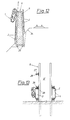
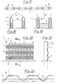
- 14 and 15 show a detail in section or in view. 16 to 19 show details.
- Fig. 20 shows another embodiment in view.
- Fig. 21 is a section along the line XXI-XXI of Fig. 20.
- Figures 22 to 28 show details, partly in section.
- Figures 29 and 30 show further embodiments in vertical section.
- Figures 31 to 40 show details, partially in view, partly in section. 41 to 47 show further design variants for the hollow bodies, each in plan and in view.
- Fig. 48 shows another detail in Cross-section.
- Fig. 49 shows another in plan and view Variant and FIGS. 50, 51 and 52 show the use of ski boots or their inner parts as a hollow body.
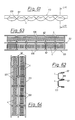
- Fig. 53 shows a planted one Element.
- 54 to 64 show the connection between Tire parts and skis.
- the protective structure 1 several arranged on its two sides Cladding elements 2 on, as it were two from each other at a distance form lying walls, each of these walls shown Embodiment two covering elements 2 lying one above the other that are lying on top of each other.
- Each of these trim elements 2 has a support structure 3 in the form of a frame-shaped slatted frame on which hollow bodies open on the outside towards at least one side or Shells, in particular tire sectors 4, are attached.
- This Tire sectors 4 are formed from used tires, in such a way that the Old tire is completely severed at one point, whereas one at one elsewhere in the tire cut from the tire opening only runs up to the tread of the tire.
- interrelated tire sectors 4 arise be pulled apart so that they are concave or convex Sides of the support frame 3 facing attached to this can.
- this attachment can be done using any Fasteners are used, e.g. Screws, dowels etc. Because neighboring tire sectors 4 are still connected in the area of the tread, can with a relatively small number of fasteners the sufficiency can be found.
- Mutual arranged cladding elements 2 walls formed in one Distance a (Fig.2) from each other, which is greater than that in the same Direction measured depth t of a cladding element 2.
- a support 6 is provided on the floor 7 rests and at least partially from a pourable material exists, which after the erection of the support structures 3 formed Cladding walls are poured into the cavity 5 from above.
- This pourable material completely fills the cavity 5 and forms one Support for the trim elements 2, which these Cladding elements against external shocks, e.g. by ascending Vehicles, stops. Since the pourable material filling the cavity 5 by its weight and by the force of the filling to remove mutual cladding elements 2 from each other, are the Cladding elements arranged on both sides of the protective structure 1 connected to each other by connecting elements 8, e.g. by steel cables provided with a corrosion protection or the like.
- This Connecting elements 8 are in particular in the bottom area of the Protective structure 1 arranged because the forces described there become most effective. It is therefore at least the lowest Cladding elements 2 connected by the connecting elements 8, However, the trim elements 2 arranged above it are also expedient. In order to prevent each cladding element 2 from tipping outwards, are the traction locking elements 8 in the bottom and arranged in the upper region of each cladding element 2. To this Way there is already a stable construction, especially since it is possible in the pourable material, which fills the cavity 5, curable Add additives, e.g. Concrete or the like At least in part however, this pourable material from at least one problem substance, i.e. from a material that has difficulty disposing of it prepares. Examples of such materials were given at the beginning.
- stiffening elements 9 can be in the support be arranged to increase the stability of the protective structure 1. in the illustrated embodiment, these stiffening elements 9 of used structural steel beams formed, which are anchored in the floor 7. How can be seen, this also results in a stiffening element 9 reasonable use for problematic materials. this is also valid for the material of the support structure 3 of the cladding elements 2, so that for almost all essential components of the protective structure 1 Possibility of using problematic material.
- the connecting elements 8 are in the material of the support 6 embedded so that this material is shifting the Connecting elements 8, for example caused by the impact of one Vehicle, counteracts.
- the material of the support 6 can be in that of the tire sectors 4 formed cavities penetrate something and these cavities partially fill in, but not completely.
- the remaining cavities are with one suitable for the growth of a planting 10 or greenery Material at least partially filled, appropriately with soil, compost or the like.
- This material can also contain additives to problematic substances, e.g. Manure, blast furnace slag or foam particles.
- the width of the support 6 does not have to be greater than the depth t everywhere a cladding element, it is sufficient if this measure of one or a few places is fulfilled to a corresponding amount Support material and the necessary stability of the To be able to achieve protective structure 1.
- the planting does not have to be provided on all cladding elements 2 or not all of the cavities formed by the tire sectors 4 one for growth the planting 10 contain suitable material. This will be later received more.
- the tire sectors 4 are provided with holes 11 through which the Planting 10 can grow through. So after a while - if this is desired - the entire protective structure 1 from the planting grow through and therefore completely green.
- FIG. 12 In the embodiment according to Figures 4 to 6 is one existing wall 12 in front, which forms part of the support 6.
- This Wall 12 is covered on one side by the cladding elements 2 and greened in this way, but such a cladding can - if desired - also be arranged on the other side of the wall 12.
- the Cladding elements 2 are at least in the lower part of the wall 12 in a distance b from the wall 12 and are by connecting elements 8 connected to the wall 12 in a tension-locking manner, e.g. using anchor bolts.
- Gap 13 is filled with pourable material, which contains at least one problem substance of the type described at the outset and in which the connecting elements 8 are embedded.
- the arrangement of the Connecting elements 8 corresponds to that according to the embodiment according to Fig.1 to 3.
- the entire support 6 for the trim elements 2 is thus here from the combination of the wall 12 with that in the intermediate space 13 introduced bulk material formed. If necessary, this Support 6 may be reinforced by stiffening elements 9.
- the cladding elements 2 also on the existing wall 12 can extend, if desired, so that the existing wall 12 is provided with an extension 14. In the area this increase are cladding elements 2 back to back arranged so that in the area of the top 14 a bilateral Greening is achieved.
- this planting 10 of the cladding elements 2 Extension 14 hangs down and so at least part of the area of the Wall 12 covers with greenery, which in Fig.6 for the left half the wall 12 is indicated.
- Fig.7a and 7b show, the protective structure does not have to be arranged vertically. Rather, both the support for Be horizontal inclined, as well as the cladding elements 2.
- Fig.7a shows an embankment 16 lying to the side of a roadway 15, the Slope has a risk of slipping.
- protective structures 1 are incorporated into the embankment, which in channels 17 lie, which are incorporated into the embankment 16. These channels 17 can, but do not have to, in the direction of the slope of the slope 16 run.
- the cladding elements 2 are in two Rows spaced from each other, the Cladding elements 2 of the two rows in pairs with each other tractive connection elements 8 are connected.
- the remaining one Space between the two rows of trim elements 2 is filled with the support 6 made of problematic material. Since the slope forces formed by the embankment 16 in the direction of the arrows 18 (Fig.7b) can exercise, it is appropriate, the connecting elements 8 also to design pressure-resistant and or or pressure-resistant stiffening elements to be arranged, which prevent the material of the support 6 is pushed out.
- Planting 10 covers structure 1 after some time. This can be done be supported that the support 6 with an overlying layer made of a material suitable for the growth of greenery becomes.
- a steep wall 19 forms part of the support 6.
- the rest of the support is by two lying on the two flanks of the steep bank 19 Layers of pourable material formed between the flanks of the Steep wall 19 and the cladding elements 2 arranged on both sides lie.
- the arranged on the individual trim elements 2 Tire sectors 4 have different sizes. On the one hand, this can be achieved in that used tires of different sizes Application, or by the fact that old tires of the same size Application come, however, by a different number of Cuts can be divided into different sized sectors. As in Fig. 8 is shown in the right half, can be done in this way achieve that the angle of repose from the front of the Tire sectors 4 formed surface deviates from the angle of repose Flank of the steep wall 19.
- Fig. 8 there is one shown another variant, in which the most Cladding element 2 arranged below 4 tire sectors protrude other tire sectors of the trim element in question. These protruding tire sectors 4 catch rainwater that runs off and therefore form a water trap. To some extent, but to a lesser extent this also applies to the gradual enlargement of the tire sectors 4 on the right side of the structure 1 according to Fig. 8.
- the cladding elements 2 in the structure 1 are step-shaped offset against each other so that the entire protective structure 1 Stair-shaped shape and deep foundations are omitted can.
- this support structure 3 consists of Crossbars 20, which by vertically extending slats 21 into one rigid frames are connected.
- the support structure 3 thus formed is so stable that the entire cladding element 2 on one of Installation site of the protective structure 1 remote location, convenient in a separate manufacturing company, can be prefabricated and complete the tire sectors and the greening they support to the Installation site of the protective structure 1 can be transported.
- the support structures 3 are each provided with cutouts 22 at their upper edges provided, in which the respective overhead scaffolding is inserted become.
- the distance at which the bilateral Cladding elements 2 are arranged from one another, in particular in lower area of the protective structure 1 may be very large if the local Circumstances allow this. In this way, a significant Place the amount of problem material in the pourable support 6.
- Fig. 10 shows that on both sides of the protective structure 1 arranged cladding elements need not be the same size. Likewise, the arrangement can be different on both sides. So Fig.10 shows that on the right side of the protective structure 1 only one only cladding element (calculated over the height of the protective structure) is arranged, whereas two cladding elements 2 lying, which are staggered against each other. From the right Half of Fig.10 is also seen that there the cladding elements 2 do not extend over the entire height of the support 6. Accordingly can the connecting elements 8, which the two-sided Cladding elements 2 hold, also run obliquely, as is the case for the top connecting element 8 is indicated.
- the 11 shows a protective structure 1, the cross section of which is strong is stepped.
- the upward facing Surface areas 23 can form management areas, ie used for agriculture, e.g. for the cultivation of vegetable plants.
- management areas ie used for agriculture, e.g. for the cultivation of vegetable plants.
- vertical surfaces agricultural use e.g. by inserting strawberry plants in the niches formed by the tire sectors.
- the stiffening elements form 9 of the support 6 is a rigid framework, which in the present case is inserted into the flank of a railway embankment 24.
- To this scaffold better anchored in the flank of the dam are at the bottom of the frame-like scaffolding anchor elements 25 in the form of transverse to the plane of Scaffolding trusses attached.
- Cladding elements 2 on both sides of the protective structure 1 arranged at different heights, they reach down to Surface of the flank of the railway embankment 24, however, can also, like this is shown for the cladding element 2 located at the bottom left, be embedded in this surface.
- plug connections 29 for the connection of the tire sectors 4 on the support frames 3.
- These plug connections have bolts 30 anchored in the frame parts of the supporting frames, onto which the tire sectors 4 are attached and by means of wedges 31 are secured.
- the upper flanks 32 of the tire sectors 4 have the Openings 11 for the use of the planting, the treads 33 of the Tire sectors 4 are provided with a perforation 34, which on the one hand ventilation for the backfilling the tire sectors 4, for the growth form the planting 10 serving material, on the other hand, a good Cause sound absorption.
- this tub 35 is on her Provide joints with a profile that the individual Sections of the tub seals against each other. At certain intervals can the tub 35 with drains 36 or collecting rooms for draining or Collection of harmful substances.
- the tub is there made of absolutely dense, corrosion-resistant material to a Prevent contamination of the soil safely.
- the support frameworks 3 of the cladding elements vertical uprights 37 onto which the tire sectors 4 with openings 38 are attached.
- the openings 38 have a cross section, which is expediently larger than that of the upright 37, so that the attachment the tire sectors 4 is facilitated and a limited flexibility, e.g. in order to accommodate manufacturing tolerances.
- Figures 18 and 19 show that when installing the protective structure 1 the scaffolding 3 of the cladding elements 2 formwork for the can form pourable material of the support 6. Everybody is here Support frame 3 covered on the inside with a perforated fleece 39, which has relatively narrow holes, so that the material of the Support 6 is substantially retained when this material, 19 shows, in the direction of arrow 40 between the Cladding elements 2 is introduced. Through the holes of this fleece 39, however, the planting 10 can grow inwards. Appropriately is carried out when the protective structure 1 is first installed Cavities in the supporting frameworks 3, that is to say those delimited by the tire sectors 4 Cavities with a material suitable for the growth of the planting above (arrows 41). Only then is the pourable poured in Support material 6.
- the tire sectors are in their natural Shape, i.e. not or hardly flattened, on the supporting framework 3 attached. 20 and 21 show, however, the tire sectors 4 can also be attached to the supporting frames 3 in a flat manner.
- the tire sectors are 4th with its flanks 32 in a hardenable material of the supporting structure 3 poured.
- This curable material can e.g. Concrete or plastic be.
- Coating 42 is provided which increases the sound-absorbing Properties of the protective structure.
- a coating 42 can for example consist of shredded straw, which in suitably bound by a binder and suitably by attached to the treads 33 of the tire sectors 4 is.
- An alternative to this is a plastic layer.
- the perforation 34 remains despite the application of the coating 42 sound absorbing effect.
- Fig. 24 are at the top of the Cladding element 2 attached tire sectors 4 arranged above Tire flanks removed so that upward openings 43rd arise, the rainwater falling in the direction of arrow 44 can catch. This will irrigate the planting favored.
- Fig. 25 shows that the tire sectors are not always with the convex sides turned outwards on the cladding elements 2 must be provided. Rather, the arrangement can also be such that the Concave sides of the tire sectors 4 face outwards. Even with one such an arrangement it can be achieved that directed upwards Openings 43 arise, this arrangement of the tire sectors even has the advantage that these openings 43 without cutting off Flank areas of the tires are to be trained.
- Fig. 26 shows that the tire sectors 4 also on horizontal or vertical slats of the support structure 3 can be attached that the See treads 33 on different sides. This makes one bilateral support for the backfill 45 of the tire sectors 4, which is formed from the material suitable for the growth of the greenery 10.
- Fig. 27 shows that it is possible to use the tire sectors 4 To remove rim areas so that only the tread areas 33 together Parts of the adjacent flanks 32 remain and on the supporting frameworks 3 are attached. This will make the tire sectors 4 flat relieved, so that there is a very narrow construction.
- the support structures 3 can be profiled 46 (Fig. 28a) instead of the cutouts 22 (FIG. 9) in order to lie one on top of the other if necessary also laterally adjacent support structures to connect with each other so that they cannot move.
- Fig.28b shows, there is a variant for this is that the support frames 3 in profile rails 47 use, e.g. consist of recycled material. Suitable for this especially recycled plastic, which is appropriately reinforced. The connection points of such recycled plastic rails can by reinforced with fiberglass fleece soaked in plastic.
- a An alternative is to use used structural steel parts for the Profile rails 47 to use.
- a wall 12 on both sides is covered by the protective structure 1.
- a e.g. constructed as a shell 48 construction embedded thus a Forms part of the support 6 and upwards from the protective structure 1 protrudes.
- This upper, possibly curved part forms an extension 49, which is a substructure for a sound trap and or or a roof, e.g. a roadway area 15 forms.
- the Extension part 49 also form a sound trap itself, if necessary old soundproofing panels can be used.
- the planting 10 in Containers 51 may be arranged, which can be pulled out like a drawer in the protective structure 1 are arranged.
- a layer 53 there can be between the surface of the protective structure 1, that is between the treads 33 of the tire sectors 4, and one or more foils 52, nonwovens or forming a cover Networks, a layer 53 may be provided, which is sound-absorbing Has properties.
- a layer can e.g. of crushed straw be formed, which is provided with a binder and so to the Tire sectors 4 is attached.
- Alternatives to this are shredded ones Plastic waste or granules from foams or slags.
- Fig. 33 shows a particularly favorable training for advertising.
- Form labels 54 for advertising purposes.
- the same effect can be achieved by visibly attached old skis or ski boots. The desire to have such labels after a certain time making it disappear can easily be taken into account be that the planting 10 after a certain time these advertisements overgrown and thereby invisible.
- Fig. 34 shows an alternative to this: Individual sections of the covers 53 can be artistically designed so that any Motifs 55 or conceptual content can be clarified.
- the protective structure does not have to be uniform over its entire length be trained. As Fig. 35 shows, it is rather also possible in individual sections of the protective structure noise protection window 56 or Arrange glass walls 57.
- Figures 36 and 37 show that as Stiffening elements 9 for the support 6 also entire track sections 58 can be used. These track sections 58 can, as Fig.36 shows, are rammed into the floor 7 with the rails 59, or, as 37 shows, with the rails 59 on uprights 60 anchored in the floor 7 be attached.
- FIG. 39 in the side wall of the pot 36 holes 61 through which the Plant can grow through.
- the attachment is particularly useful such holes 61 in combination with the removed bottom of the pot 60.
- FIG. 39 also shows, it is advantageous to cover the side wall 62 with a Cut cut 63.
- this has the advantage that the pot 60 (provided that the bottom is removed) to one any size can be reduced.
- the Advantage that the plant can grow the pot 60 after sufficient growth can expand widely.
- a band 64 made of elastic material in particular a rubber ring
- band 64 holds the pot edge together. If necessary, this tape 64 can be removed later.
- a An alternative to this is the band 64 made of one material form, which rots over time and through the plant is blown up by itself.
- the cladding elements, which are now green 2 are then taken to the place of use of the protective structure and mounted there. This results in a considerable saving in assembly costs.
- When inserting the pots or ski boots into the holes of the Tire sectors 4 is expediently a short section of the pot or Ski boots let protrude over the associated planting hole 11 to the to catch natural irrigation.
- the elements can also be used entirely be planted and initially remain in this state for a long time Outdoors.
- the Prune plants it is advisable, during the growing process of the plants, that is, in the case of pots 60 still at the removal location of the plants, the Prune plants to achieve dense vegetation, preferably several times at intervals.
- the material of the pots 60 can, but need not, be rotten. Peat, cardboard or is particularly suitable as a decomposable material stronger paper.
- the pots 60 are made of non-rotting material trained, the growth process of the plants can take a long time take place without the risk that the pots will suffer 60 damage.
- the aforementioned planting in pots and the transfer the pots in openings of the tire sectors can also be used differently Use protective structures of any kind, especially for protective structures that are designed in accordance with European Patent Specification 273 911. All that is required is to insert the pots into openings in Used tires for the purpose of greening a protective structure.
- the scaffolding 3 can Cladding elements 2 be self-supporting, so that separate from the Stiffening elements 9 brackets formed with the exception of the support 6 are dispensable if the conditions permit this.
- the Supporting structures can, but need not, be connected to each other.
- For a connection of neighboring scaffolding can conventional Use lanyards, e.g. Dowels, screws, brackets etc., if necessary with the use of old skis or surfboards.
- Similar Elements can be used to connect stiffening elements serve with each other or for fastening the tire sectors to the associated scaffolding. It is advisable to use these connecting means to be corrosion-resistant, e.g. made of plastic.
- Fasteners e.g.
- the fasteners of Thorns are formed, especially for the definition of the tire sectors on the scaffolding.
- Such mandrels are similar to that in Figs. 14 and 15 Type of fastening shown, because the bolts 30 shown there can easily be formed like a thorn. Instead of the backup serving wedges 31 then occurs a bending of the mandrel or a split pin.
- the pourable material that is used for Filling out of the tire sectors or other hollow bodies or serving bowl-shaped elements limited cavities from that material be different, which is used to fill the cavities 5 for support 6 serves.
- the support structure 3 on the inside one of the pourable material of the support 6 of the for the growth of Planting 10 serving material separating layer 39 (Fig. 18,19) or at least the formwork mentioned in this context to use.
- Sound side of the structure i.e. the outside or the carriageway 15 facing side of the structure 1, sound absorbing material, e.g.
- foamed plastic, rock wool or the like as material for the Filling the cavities of the tire sectors 4 and / or the cavities the scaffolding 3 to use.
- This material can be used for a The greening of suitable material grew to be mixed on this as well Preservation of greenery, but this is not mandatory, since not all tire sectors must be green.
- the protective structure 1 can also be used for special purposes.
- One such special purpose is the utilization of geothermal energy.
- Fig.3 shows, inside the protective structure 1 or its pipes 65 formed by the cladding elements, e.g. in Form of heating coils, embedded, through which a heating medium is conducted, which is heated by geothermal energy in a manner known per se.
- FIG.3 Another possibility is to arrange additional ones Sound absorption elements 66 (Fig.3).
- a preferred design is in doing so in the form of trapezoidal sheets 67, which are attached at an angle to the top of the protective structure 1.
- the horizontal trapezoidal sheet area can be one Irrigation gutter 68, e.g. for rainwater.
- the source of noise turned and is made of a layer 69 on its underside sound-absorbing material provided as additional sound insulation.
- foamed plastic which is designed as a perforated soundproofing body, pressed rock wool or layers of glass fleece arranged in layers, which with a Binders are reinforced.
- Hoses 70 be connected through which water to the lower sections of the Protective structure 1 is headed.
- Such hoses 70 can from used hoses of all kinds, e.g. used fire hoses, be formed, since a complete tightness is not required.
- Another special purpose is that inside the Protective structure of supply lines, in particular electrical lines and or or cable channels are embedded, preferably in the pourable Material of the support 6.
- Such a cable duct 71 is shown in FIG. 29 shown.
- noise protection panels 72 are noise protection panels expediently arranged on the rear of the tire sectors 4 and can be embedded in the material of the supporting framework 3 (Fig. 23).
- ventilation lines 73 can be provided with what air can be supplied to the material of the support 6 and or or to the material used for the growth of the planting 10. These ventilation lines 73 can be connected to fans, with which exhaust air from traffic routes into the ventilation ducts 73 is initiated.
- Additional irrigation lines 74 can be provided be to water the material used for the growth of the planting 10 feed.
- These irrigation pipes can be made from old material, e.g. Recycled plastic, exist, but also from used, discarded Fire hoses should be formed.
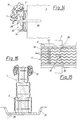
- the irrigation pipes can on Water tank 75 connected, which is inside the Protective structure 1 is arranged, preferably embedded in the material the support 6. From this water tank 75, the water can reach the higher areas of the protective structure 1 are pumped up or it can this water tank 75 be designed as a high tank, which is used in particular to collect rainwater. Possibly can also the rainwater outside the protective structure areas can be supplied via feed lines and pumps. In this case, recommends However, there is a filter system for cleaning the water.
- Devices for generating solar energy e.g. Solar panels 77 (Fig. 1,3) can be provided.
- the energy generated with it can be used to pump the irrigation systems and / or or to feed electrically operated advertising systems.
- Areas of application for protective structures of the type according to the invention include: greening of buildings, garden borders, walls around Firing ranges, camouflage walls, splinter protection walls, protective structures for Avoiding soil erosion, especially for reforestation Karst areas, avalanche barriers, cladding of slopes, safety devices against landslides, securing bank embankments, dismantling for Traffic areas, boundaries of traffic areas, which of Different participants can be used, cladding walls of all Type, cladding of guard rails and other lane boundaries, and many other uses.
- cup-shaped elements can be made another material, in particular problem material, e.g. Ski boots made of straw soaked in a binder bowl - shaped elements, pressed cardboard or paper waste in Shell shape, waste plastic, possibly recycled plastic, as Shells formed, glass fleece parts in the form of a shell, with a hardener impregnated facade nets in the form of shells, lightweight concrete shells, if necessary with foam inserts.
- problem material e.g. Ski boots made of straw soaked in a binder bowl - shaped elements, pressed cardboard or paper waste in Shell shape, waste plastic, possibly recycled plastic, as Shells formed, glass fleece parts in the form of a shell, with a hardener impregnated facade nets in the form of shells, lightweight concrete shells, if necessary with foam inserts.
- These bowls would be useful - just like the tire sectors - with perforations to improve the Sound absorption or openings for inserting the planting Mistake.
- bowl-shaped elements which if necessary made by molding using molds there
- Fig. 41 shows a variant in the plan and in view, which on a facing shell 81 of the protective structure, which be formed by a trim element of the type previously described can, a sound absorbing layer 82 on that of the sound Is arranged in which layer cans 83 are embedded, so that the product labels 84 (see the view representation of the Fig. 41) can read.
- This allows advertising effects to be achieved.
- these advertising labels can be predefined Make time invisible by greening it be overgrown.
- Fig. 42 shows a variant of this. Like the one on the left Floor plan shows, are on the sound absorbing layer 82, which is applied to the front shell 81, played tennis balls 85 attached, e.g. by embedding in layer 82 (left illustration 42, above), or by attachment, e.g. Gluing or nailing. These tennis balls 85 can be arranged individually, what in the right View representation of Figure 42 is shown above, or you can represent a closed association, what in the right representation 42 is illustrated below. These tennis balls 85 can, as well how the side walls of the cans 83 (Fig. 41) have perforations to the improve sound-absorbing behavior.
- the cans 83 (Fig. 41) have the open side up and can have a filling, e.g. out sound-absorbing or sound-absorbing material, or one for the Growing a suitable material.
- the Fig. 43 shows the left in the plan and the right in the view Use of ski boots 86, together with a sound absorbing Layer 82 are attached to the facing shell 81.
- the ski boots 86 can be arranged so that the heel region 87 of the sound source is turned. To achieve additional noise reduction, can this heel area 87 may be provided with a perforation 88.
- the cavities 89 of the ski boots 86 can serve as pots for planting.
- Fig. 44 shows a plan view on the left and a view on the right Variant in which on the sound-absorbing layer 82 Cover 81 old film rolls 90 or their containers and or or Food cup 91, e.g. Yogurt cups are attached.
- the sound-absorbing layer 82 Cover 81 old film rolls 90 or their containers and or or Food cup 91, e.g. Yogurt cups are attached.
- the arrangement of these sound absorbing components in mutual Distance or in tight packing.
- Fig. 45 shows the plan on the left and the view on the right Use of ski boots 86 attached to skis 92, e.g. by means of the usual binding.
- the ski boots 86 can be used with a Perforation 88 may be provided, additional skis 93 and 94 form one Horizontal or diagonal stiffening.
- the ski boots are 86 arranged between upright, vertical skis 92 and attached to it.
- Fig. 47 which one on the left Floor plan and a view on the right are the ski boots 86 with openings 95 of the sole, which openings from the skis 92 are penetrated so that the ski boots 86 are, as it were, attached to the skis 92 are.
- two openings are advisable per ski boot 86 provided, one of which is a top view of seen the ski boot 86, in the area of the foot opening 96 of the ski boot 86 lies, so that only the sole of the ski boot has to be perforated here.
- the other opening 95 is arranged in the instep area of the ski boot 86. The instep area and the sole must be perforated here.
- the skis 92 need not always be arranged the same way, they can rather both the tread and the top side as well facing the edge side of the sound source. It is particularly cheap To direct the tread to the outside, because this way the attached ones Company inscriptions can be used for advertising purposes.
- cladding elements 2 on both sides of the protective structure provided, each of which forms a facing shell 81.
- a pourable material 97 is arranged, which is problematic contains that are dirty, so that this material as possible should not come into contact with the environment.
- the moisture and chemical proof is that the pollution the fill 97 cannot get into the environment.
- the embodiment according to Fig. 49 shows a construction which to use solar energy.
- This is on the front cover 81 a thermally conductive one that absorbs solar energy as much as possible Layer 99 attached.
- this layer 99 there are heating coils 100 embedded.
- the heat transfer medium flowing in these heating coils 100 is heated by the solar energy absorbed by layer 99.
- the outer surface 101 of the layer 99 is darker Color kept.
- 99 hollow bodies, e.g. perforated boxes 83 or longitudinally cut ski boots, embedded be partially protruding from the layer 99 and with heat absorbing Granules are filled. This will make the effective area which exposed to sunlight, enlarged.
- FIG. 50 shows schematically how an entire ski boot 86 (upper Representation) cut into individual parts 102 (lower representation) can be used individually as a hollow body in the sense of the invention can find, optionally provided with a perforation 88.
- Fig. 51 shows a variant of this:
- the ski boot 86 is in here its longitudinal direction by a vertical section into two parts 102 Cut.
- the inner part 103 is removed from the ski boot 86 and separated can be used as a hollow body. This can be done by order a perforation 88 (middle illustration of Fig. 52), whereby the inner part 103 has a noise-dampening effect. Additionally or alternatively to this the inner part 103 as a receptacle for the soil of a greenery 104 use. This earth is ventilated through perforation 88 and it can drain off excess water.
- the embodiment according to FIG. 53 shows how with a greening 104 provided elements 105 can be formed. For this it is advisable to provide these elements 105 lying on the natural floor 106 and to train from good earth (humus).
- the used in rows Greenery 104 can be in hollow bodies of the type described above in the Element 105 are used, which then as a whole, appropriately in a suitable support, transported to the place of use can be.
- Tire flanks 108 are cut open and the resulting flaps on Support structure 3 or the like. be attached.
- Flaps of the cut tire flanks 108 become cavities 110 limits which planting holes form for greening.
- a punch 111 of the tire flank sections 108 makes it easier for the greening Streaky.
- the flap-shaped parts of the tire flanks Adjacent tires overlapping each other to be attached to the support structure 3.
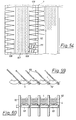
- Fig. 55 shows the attachment in plan and Fig. 56 in view of interrelated tire sectors 4 on skis 92 which form part of the support structure 3 for the tire sectors 4.
- the of interconnected tire sectors 4 chain is formed horizontal, the skis 92 run vertically and are arranged so that the company name on the skis is for advertising purposes remains visible.
- Between each other, lying on top of each other Layers of the tire sectors 4 can be provided with planting holes 112.
- FIG. 57 A variant of this is shown in Fig. 57 in plan and 58 in view.
- the skis 92 are also vertical, but in such a way that the Point the side edges outwards and inwards. This will make the greening left more room for growing through.
- 59 floor plan
- 60 View
- tire sectors 4 one below the other connected and by vertical skis 92 in vertical Direction are supported, with additional skis 93 being horizontal, inclined, form cross connections. This is the construction braced.
- FIGS. 61 to 63 A variant of this is shown in FIGS. 61 to 63, wherein Fig.61 this variant in plan and Fig.63 this variant in view represents.
- Fig. 62 is a section along the line LXII - LXII of Fig. 61.
- This embodiment variant shows prefabricated elements 113 in which skis 92 running horizontally and parallel to one another are provided, on which the tire flanks 108 of the possibly interrelated Tire sectors 4 are attached, e.g. by screwing, Dowels or the like These elements 113 can be prefabricated in the factory and then transported to the construction site in the prefabricated state and there be transferred.
- Fig. 64 shows an alternative to this.
- Elements 113 are here formed in the same way as in the variant according to the Fig. 61 to 63 is the case, however, the finished elements 113 on the site so that the skis 92 are vertical.
Landscapes
- Engineering & Computer Science (AREA)
- Architecture (AREA)
- Civil Engineering (AREA)
- Structural Engineering (AREA)
- Road Paving Structures (AREA)
- Cultivation Receptacles Or Flower-Pots, Or Pots For Seedlings (AREA)
- Polymerisation Methods In General (AREA)
- Shaping Of Tube Ends By Bending Or Straightening (AREA)
Description
Claims (67)
- Schutzaufbau (1), welcher auf seinen beiden Seiten je zumindest ein Verkleidungselement (2) aufweist, welches ein Traggerüst (3) besitzt, an welchem zumindest einseitig offene Hohlkörper befestigt sind, wobei zumindest einige der von diesen Hohlkörpern gebildeten Hohlräume zumindest ein für den Wuchs einer Bepflanzung (10) geeignetes Material enthalten, und wobei für die beiderseitigen Verkleidungselemente (2) eine zwischen ihnen angeordnete, auf dem Boden aufliegende oder mit dem Boden verbundene Abstützung (6) vorgesehen ist, deren normal zur Aufbauebene gemessene größte Breite größer ist als die in der gleichen Richtung gemessene Tiefe eines Verkleidungselementes (2), und wobei diese Abstützung (6) zumindest teilweise aus schüttbarem Material besteht, dadurch gekennzeichnet, daß zumindest das schüttbare Material der Abstützung (6) zumindest einen Problemstoff enthält und daß in der Abstützung (6) Verbindungselemente (8) für die beidseitigen Verkleidungselemente (2) angeordnet sind, die in das schüttbare Material eingebettet sind und mit den Verkleidungselementen (2) derart verbunden sind, daß die beidseitigen Verkleidungselemente (2) zumindest im Bodenbereich des Schutzaufbaues (1) zugschlüssig miteinander verbunden sind, wobei die Verbindungselemente (8) und/oder die Verkleidungselemente (2) Problemmaterial enthalten, das von Altreifen abweicht und aus dem starren Zustand seines Anfallens nicht oder nicht wesentlich verändert ist.
- Zumindest einseitig bepflanzbarer Schutzaufbau (1), bei welchem an zumindest einer Seite einer starren, mit dem Boden (7) verbundenen Abstützung (6) zumindest ein Verkleidungselement (2) vorgesehen ist, welches ein Traggerüst (3) aufweist, an welchem zumindest einseitig offene Hohlkörper befestigt sind, wobei zumindest einige der von diesen Hohlkörpern gebildeten Hohlräume zumindest ein für den Wuchs einer Bepflanzung (10) geeignetes Material enthalten, dadurch gekennzeichnet, daß zumindest im unteren Bereich der Abstützung (6) die Verkleidungselemente im Abstand von der Abstützung (6) angeordnet sind und daß der verbleibende Zwischenraum mit schüttbarem Material ausgefüllt ist, wobei zumindest dieses schüttbare Material zumindest einen Problemstoff enthält und daß in dieses schüttbare Material Verbindungselemente (8) eingebettet sind, mit welchen zumindest im unteren Bereich der Abstützung (6) zumindest ein Verkleidungselement (2) in seinem unteren Bereich zugschlüssig mit der Abstützung (6) verbunden ist, wobei die Verbindungselemente (9) und/oder die Verkleidungselemente (2) Problemmaterial enthalten, das von Altreifen abweicht und aus dem starren Zustand seines Anfallens nicht oder nicht wesentlich verändert ist.
- Schutzaufbau nach Anspruch 1 oder 2, dadurch gekennzeichnet, daß die Abstützung (6) einen bestehenden Aufbau, einen Hang, eine Böschung (16), einen Lärmschutz- oder Winderosionsdamm oder eine Uferböschung mit einschließt, wobei verbleibende Hohlräume (9') mit Problemstoffmaterial und bzw. oder Abraum aus dem bestehenden Aufbau ausgefüllt sind und der Anschluß des Schutzaufbaus mittels Zugankern erfolgt.
- Schutzaufbau nach einem der Ansprüche 1 bis 3, dadurch gekennzeichnet, daß die Hohlkörper von Reifensektoren (4) und bzw. oder Dosen (83) und bzw. oder Skischuhen (86) gebildet sind.
- Schutzaufbau nach Anspruch 4, dadurch gekennzeichnet, daß die Hohlkörper gelocht sind.
- Schutzaufbau nach Anspruch 5, dadurch gekennzeichnet, daß Reifensektoren (4) an den Seitenflanken gelocht sind.
- Schutzaufbau nach einem der Ansprüche 1 bis 6, dadurch gekennzeichnet, daß das Problemmaterial der Verbindungselemente (8) und bzw. oder der Verkleidungselemente (2) von Schiern (92,93,94), Schischuhen (86) oder Dosen (83) gebildet ist.
- Schutzaufbau nach einem der Ansprüche 1 bis 7, dadurch gekennzeichnet, daß die Abstützung (6) zur Horizontalen geneigte, den Verkleidungselementen zugewendete Begrenzungsflächen hat und daß auch die Verkleidungselemente (2) geneigt angeordnet sind.
- Schutzaufbau nach einem der Ansprüche 1 bis 8, dadurch gekennzeichnet, daß er eine Aufstockung (14) eines bestehenden Aufbaues bildet.
- Schutzaufbau nach einem der Ansprüche 1 bis 9, dadurch gekennzeichnet, daß die Verkleidungselemente (2) auf den beiden Seiten der Abstützung (6) auf unterschiedlicher Höhe angeordnet sind.
- Schutzaufbau nach einem der Ansprüche 1 bis 10, dadurch gekennzeichnet, daß er im Querschnitt treppenförmige Gestalt hat, wobei die nach oben gerichteten Oberflächenbereiche (23) Bewirtschaftungsflächen bilden.
- Schutzaufbau nach Anspruch 11, dadurch gekennzeichnet, daß die Verkleidungselemente (2) selbsttragende übereinander angeordnete miteinander verbundene Traggerüste (3) haben, die treppenartig angeordnet sind und bzw. oder die Hohlkörper unterschiedlicher Größe aufweisen, wobei für Reifensektoren (4) diese unterschiedliche Größe durch Verwendung von Altreifen unterschiedlicher Größe und bzw. oder durch unterschiedlich große Sektorwinkel der Reifensektoren (4) erzielt ist.
- Schutzaufbau nach einem der Ansprüche 1 bis 12, dadurch gekennzeichnet, daß die Hohlkörper der Verkleidungselemente (2) zumindest ein Problem material der in Anspruch 1 genannten Art enthalten.
- Schutzaufbau nach Anspruch 13, dadurch gekennzeichnet, daß die Hohlkörper Aufschriften tragen, die der Außenseite des Schutzaufbaues (1) zugekehrt sind, wobei im Inneren der Hohlkörper zumindest ein schallabsorbierendes Material (66) vorhanden ist.
- Schutzaufbau nach einem der Ansprüche 1 bis 14, dadurch gekennzeichnet, daß die Abstützung (6) starre Versteifungselemente (9) enthält, die aus Problemmaterial der in Anspruch 1 genannten Art besteht.
- Schutzaufbau nach Anspruch 15, dadurch gekennzeichnet, daß die starren Versteifungselemente (9) die zu beiden Seiten des Schutzaufbaues (1) angeordneten Verkleidungselemente (2) drucksteif verbinden.
- Schutzaufbau nach Anspruch 15 oder 16, dadurch gekennzeichnet, daß die Versteifungselemente (9) im Boden (7) verankerte, bereits bestehende und bzw. oder in den Boden eingerammte Steher aufweisen.
- Schutzaufbau nach einem der Ansprüche 15 bis 17, dadurch gekennzeichnet, daß die Versteifungselemente (9) ein starres Gerüst in Rahmen- oder A-Form, bilden, an dem im Boden zu verlegende Ankerelemente (25) befestigt sind.
- Schutzaufbau nach einem der Ansprüche 15 bis 18, dadurch gekennzeichnet, daß die Versteifungselemente (9) horizontal oder vertikal und parallel zueinander verlaufende Montageleisten (26) in Form von mit Profilierungen (27) versehenen Schienen aufweisen, zwischen welche die Traggerüste (3) der Verkleidungselemente (2) mit den Profilierungen (27) der Montageleisten (26) entsprechenden Profilierungen (28) eingesetzt sind.
- Schutzaufbau nach einem der Ansprüche 15 bis 19, dadurch gekennzeichnet, daß die Abstützung (6) Hohlräume (5) zwischen den Versteifungselementen (9) enthält, die mit dem schüttbaren, zumindest einen Problemstoff enthaltenden Material ausgefüllt sind.
- Schutzaufbau nach einem der Ansprüche 1 bis 20, dadurch gekennzeichnet, daß Steckverbindungen (29) für den Anschluß der starren Versteifungselemente (9) aneinander und bzw. oder zur Befestigung der Hohlkörper an den Traggerüsten (3) und bzw. oder zur Befestigung der Verkleidungselemente (2) an der Abstützung (6) und bzw. oder zur Befestigung des aufzustockenden Schutzaufbaues (1) vorgesehen sind.
- Schutzaufbau nach einem der Ansprüche 1 bis 21, dadurch gekennzeichnet, daß zur Verbindung von Versteifungselementen (9) und bzw. oder Hohlkörpern mit dem Traggerüst (3) korrosionsfeste Dübel, Keile (31), Klammern oder Nieten dienen.
- Schutzaufbau nach einem der Ansprüche 1 bis 22, dadurch gekennzeichnet, daß sich unter der Abstützung (6) eine Wanne (35) aus dichtem korrosionsbeständigem Material befindet, deren in Längsrichtung des Schutzaufbaues (1) verlaufende Abschnitte an ihren Stoßstellen oder Anschlüssen an die Abstützung (6) durch eine Profilierung abgedichtet sind.
- Schutzaufbau nach einem der Ansprüche 1 bis 23, dadurch gekennzeichnet, daß korrosionsbeständige Befestigungsmittel für die Befestigung der Hohlkörper und bzw. oder zur Befestigung der Traggerüste (3) an der Abstützung (6) und bzw. oder an den Verbindungselementen (9) in das Material der Traggerüste (3) bzw. der Abstützung (6) bzw. der Verbindungselemente (8) eingegossen sind und daß an diesen Befestigungsmitteln Abzugssicherungen für die befestigten Konstruktionsteile vorgesehen sind, nämlich Splinte oder Umbiegungen von Dornen.
- Schutzaufbau nach einem der Ansprüche 1 bis 24, dadurch gekennzeichnet, daß die Traggerüste (3) Steher (37) aufweisen, auf welche die mit Öffnungen (38) versehenen Hohlkörper aufgesteckt sind, wobei die Öffnungen (38) größer sind als der Querschnitt der Steher (37).
- Schutzaufbau nach einem der Ansprüche 1 bis 25, dadurch gekennzeichnet, daß die Traggerüste (3) der Verkleidungselemente (2) eine Schalung für das schüttbare Material der Abstützung (6) bilden, wobei das Traggerüst (3) auf der Innenseite mit einer das schüttbare Material von dem für den Wuchs der Bepflanzung (10) dienenden Material trennenden Schicht versehen ist und bzw. oder daß das Traggerüst (3) mit den Hohlkörpern außen und innen in eine Schichte aus schallabsorbierendem und bzw. oder wärmedämmendem oder wärmeleitendem Material eingebettet ist.
- Schutzaufbau nach Anspruch 26, dadurch gekennzeichnet, daß die zu beiden Seiten der Schalung liegenden Hohlräume mit schüttbarem Material unterschiedlicher Beschaffenheit ausgefüllt sind, und zwar an der Schallseite des Aufbaues mit schallabsorbierendem Material.
- Schutzaufbau nach einem der Ansprüche 1 bis 27, dadurch gekennzeichnet, daß an zumindest einem Traggerüst (3) mehrere Reifensektoren (4) flachgezogen befestigt sind.
- Schutzaufbau nach Anspruch 28, dadurch gekennzeichnet, daß das Traggerüst (3) aus horizontal und bzw. oder vertikal verlaufenden Skis (92,93,94) besteht.
- Schutzaufbau nach einem der Ansprüche 1 bis 29, dadurch gekennzeichnet, daß an zumindest einem Verkleidungselement (2) Hohlkörper in ein härtbares Material des Traggerüstes (2) eingegossen sind.
- Schutzaufbau nach einem der Ansprüche 1 bis 30, dadurch gekennzeichnet, daß an der Innenseite und bzw. oder der Außenseite der Hohlkörper Beschichtungen (42) in Form einer. gelochten Schichte aus schallabsorbierendem und zugleich wärmedämmendem oder wärmeleitendem Material, und bzw. oder Folien, bzw. Vliese, die mit einer Lochung versehen sind und bzw. oder gebrauchte Fassadennetze in zumindest einer Lage zur Erhöhung der Schallabsorption vorgesehen sind.
- Schutzaufbau nach einem der Ansprüche 4 bis 31, dadurch gekennzeichnet, daß an zumindest einem Verkleidungselement (2) die oben angeordneten Reifenflanken der obersten Reifensektoren (4) entfernt sind.
- Schutzaufbau nach einem der Ansprüche 4 bis 32, dadurch gekennzeichnet, daß an zumindest einem Verkleidungselement (2) zumindest zwei Lagen von Reifensektoren (4) vorgesehen sind, bei denen die Laufflächen nach unterschiedlichen Seiten sehen.
- Schutzaufbau nach einem der Ansprüche 4 bis 33, dadurch gekennzeichnet, daß an zumindest einigen Reifensektoren (4) die Felgenbereiche entfernt sind, so daß nur die Laufflächenbereiche, gegebenenfalls mit den ihnen benachbarten Flankenbereichen, an den Traggerüsten (3) befestigt sind.
- Schutzaufbau nach einem der Ansprüche 1 bis 34, dadurch gekennzeichnet, daß zumindest ein Traggerüst (3) eine Profilierung (46) hat, die in eine entsprechende Profilierung eines Versteifungselementes (9) der Abstützung (6) und bzw. oder eines anderen Traggerüstes (3) und bzw. oder in eine Montageleiste paßt.
- Schutzaufbau nach einem der Ansprüche 1 bis 35, dadurch gekennzeichnet, daß die Traggerüste (3) der Verkleidungselemente (2) armierte Profilstäbe aus Recycling kunststoff aufweisen.
- Schutzaufbau nach einem der Ansprüche 1 bis 36, dadurch gekennzeichnet, daß zumindest einige Verkleidungselemente (2) und bzw. oder die Abstützung (6) eine Stahlversteifung aufweisen, die mit einem Korrosionsschutz versehen ist.
- Schutzaufbau nach einem der Ansprüche 1 bis 37, dadurch gekennzeichnet, daß das schüttbare Material Stahlabfälle, Kunststoffabfälle in zerkleinerter Form, Schaumstoffe, gepreßtes verklebtes Stroh, Glasfaservliesteile, Kompost, Klärschlamm, Gülle, Hochofenschlacke, Zellstoffabfälle, Gleisschotter, Holzschnitzel, Tonkugeln, Sand Kies, Gras, Gesträuch, Häckselgut, Papier- oder Kartonabfälle, Gesteinsmehl, Lehm, zerkleinerter Müll, Lavagestein, Asche, synthetische oder natürliche Fasem, Bodenaushubmaterial, Restbetonabfall, Tunnelausbruchmaterial oder Bauschutt enthält.
- Schutzaufbau nach Anspruch 38, dadurch gekennzeichnet, daß das schüttbare Material Zusätze von Wachstumsverbesserern für die Begrünung, Feuchtigkeitsspeichermitteln, Korrosionsschutzmitteln oder fäulnishemmenden Mitteln enthält, wobei eine dichte Schichte zur Trennung verschmutzten Schüttmateriales von reinem Schüttmaterial vorhanden ist.
- Schutzaufbau nach einem der Ansprüche 1 bis 39, dadurch gekennzeichnet, daß als Problemmaterial in den Versteifungselementen (9) der Abstützung (6) und bzw. oder in den Traggerüsten (3) und bzw. oder in den Verbindungselementen Schienen (59), Eisenbahnschwellen, Trapezbleche, Spundwände, Leitschienen, Gleisabschnitte (58) (mit den Schienen verbundene Schwellen, welche horizontal oder vertikal angeordnet sind), Kunststoffprofile aus Recyclingkunststoff, Sportartikel, nämlich Ski (92,93,94), Surfboards, Tennisschläger, Holzteile nämlich Telegrafen- oder Strommasten oder Abfallholz, in Formen verpreßte Leder- und Aluminiumabfälle, hohle ausgegossene Bauteile, Glasvliesteile, Stahlseile, zerkleinertes und mit Klebemittel gebundenes Stroh, mit Kunstharzen gebundene Schaumstoffe und bzw. oder Kunststoffabfälle und bzw. oder Staub und bzw. oder Schlamm, gewellte Dachdeckungselemente oder zusammenhängende Reifensektoren dienen, wobei korrosionsanfällige Materialien mit einer korrosionshemmenden Imprägnierung und bzw. oder Ummantelung versehen sind.
- Schutzaufbau nach Anspruch 40, dadurch gekennzeichnet, daß die für die Versteifungselemente (9) bzw. die Traggerüste (3) bzw. die Verbindungselemente (8) bzw. die Hohlkörper verwendeten Bauteile Aufschriften (54) tragen, welche der Außenseite des Schutzaufbaues (1) zugewendet sind oder an dieser Außenseite liegen.
- Schutzaufbau nach einem der Ansprüche 1 bis 41, dadurch gekennzeichnet, daß er in seinem Inneren eingebettet in das schüttbare Material (97) bzw. im Inneren einer Vorsatzschale (81) aus Hohlkörpern, welche in einer Schichte (82) aus wärmeleiffähigem und hochabsorbierendem Material eingebettet sind, Rohre (65) zur Nutzung von Sonnen-bzw. Erdwärme aufweist.
- Schutzaufbau nach einem der Ansprüche 1 bis 42, dadurch gekennzeichnet, daß er zusätzliche Schallabsorptionselemente (66) in Form von Trapezblechen (67) aufweist, welche abgewinkelt an der Oberseite des Schutzaufbaues befestigt sind, wobei der horizontal liegende Trapezblechbereich eine unten und bzw. oder seitlich gelochte Verteilerrinne (68) für die Bewässerung des Aufbaues bildet und der schräg verlaufende Oberteil an seiner Unterseite mit schallabsorbierendem Material (69) als zusätzlicher Schallschutz versehen ist.
- Schutzaufbau nach Anspruch 43, dadurch gekennzeichnet, daß an die Verteilerrinne (68) Schläuche (70) angeschlossen sind, welche zur Zuleitung von Wasser zu den unteren Abschnitten des Schutzaufbaues (1) dienen.
- Schutzaufbau nach einem der Ansprüche 1 bis 44, dadurch gekennzeichnet, daß die Hohlkörper mit Lärmschutzpaneelen (72) verbunden sind.
- Schutzaufbau nach einem der Ansprüche 1 bis 45, dadurch gekennzeichnet, daß die Abstützung (6) in Form einer nach oben gerichteten Verlängerung (49) einer bestehenden Abstützung (6) einen mit absorbierendem Material versehenen Schallfang und bzw. oder eine Überdachung von Fahrbahnbereichen oder eine Unterkonstruktion für eine(n) solche(n) bildet.
- Schutzaufbau nach Anspruch 46, dadurch gekennzeichnet, daß der Schallfang und bzw. oder die Überdachung alte Paneele aufweist, wobei das absorbierende Material gelochte, mit schallabsorbierenden Stoffen gefüllte Dosen aufweist.
- Schutzaufbau nach einem der Ansprüche 1 bis 47, dadurch gekennzeichnet, daß er in seinem Inneren eingebettet in das schüttbare Material Ver- und bzw. oder Entsorgungsleitungen aufweist.
- Schutzaufbau nach einem der Ansprüche 1 bis 48, dadurch gekennzeichnet, daß er Belüftungsleitungen (73) zur Zuleitung von Luft zu den Problemstoffen und bzw. oder zu dem für den Wuchs der Bepflanzung (10) geeigneten Material aufweist, welchen Belüftungsleitungen (73) Abluft von Verkehrswegen zugeführt ist.
- Schutzaufbau nach einem der Ansprüche 1 bis 49, dadurch gekennzeichnet, daß die Bepflanzung (10) in das für ihren Wuchs geeignete Material in Töpfen (60), bzw. Skischuhen (86) bzw. Skischuhteilen, bzw. Nahrungsmittelbechern (91) eingesetzt ist, wobei die Töpfe (60) aus korrosionsbeständigem Problem material bestehen.
- Schutzaufbau nach Anspruch 50, dadurch gekennzeichnet, daß seitlich aufgeschnittene Töpfe (60) bzw. Nahrungsmittelbecher (91) an der Oberseite durch elastische Bänder (64) zusammengehalten sind.
- Schutzaufbau nach Anspruch 50 oder 51, dadurch gekennzeichnet, daß die Töpfe (60), Skischuhe (86) oder Skischuhteile in Pflanzlöcher eingesetzt sind und mit ihrem oberen Rand über das Pflanzloch herausragen.
- Schutzaufbau nach einem der Ansprüche 1 bis 52, dadurch gekennzeichnet, daß die Bepflanzung (10) in Behältern angeordnet ist, die austauschbar im Schutzaufbau (1) angeordnet sind.
- Schutzaufbau nach einem der Ansprüche 1 bis 53, dadurch gekennzeichnet, daß die Oberflächen des Schutzaufbaues (1) mit einer Abdeckung und bzw. oder Beschichtung (53) in Form zumindest eines Netzes und bzw. oder Vlieses (39) und bzw. oder Folienmateriales versehen sind, wobei diese Abdeckung mit einer entfernbaren Bedruckung (55) und bzw. oder Bemalung versehen ist.
- Schutzaufbau nach Anspruch 54, dadurch gekennzeichnet, daß zwischen der Abdeckung und der Oberfläche des Schutzaufbaues (1) zusätzliches schallabsorbierendes Material, nämlich geschäumter Kunststoff, zerkleinertes Stroh, Granulate oder zerkleinerte Kunststoffabfälle, eingefüllt ist und bzw. oder auf der Rückseite der Abdeckung eine schallreflektierende Schicht angebracht ist.
- Schutzaufbau nach einem der Ansprüche 1 bis 55, dadurch gekennzeichnet, daß er Bewässerungsleitungen (74) aus Altmaterial, nämlich Recyclingkunststoff, gebrauchte Feuerwehrschläuchen oder Trapezbleche, enthält.
- Schutzaufbau nach einem der Ansprüche 1 bis 56, dadurch gekennzeichnet, daß er in seinem Inneren zumindest einen Wasserbehälter (75) aufweist, welchem Wasserbehälter (75) eine Pumpe zur Zuleitung von Regenwasser aus außerhalb des Schutzaufbaues (1) gelegenen Flächenbereichen zugeordnet ist.
- Schutzaufbau nach Anspruch 57, dadurch gekennzeichnet, daß die Pumpe mit einer Filteranlage zur Reinigung des Wassers kombiniert ist.
- Schutzaufbau nach einem der Ansprüche 1 bis 58, dadurch gekennzeichnet, daß er in seinem Inneren Zuleitungen für Erdfeuchtigkeit aufweist.
- Schutzaufbau nach einem der Ansprüche 1 bis 59, dadurch gekennzeichnet, daß er Werbeflächen oder -anlagen in durch die Bepflanzung (10) überwachsbarer Anordnung, und bzw. oder Warnanlagen und bzw. oder Überwachungsanlagen trägt.
- Schutzaufbau nach einem der Ansprüche 1 bis 60, dadurch gekennzeichnet, daß zumindest einige Verkleidungselemente (2) und bzw. oder einige Abschnitte der Abdeckungen an der Außenseite farblich gestaltet und bzw. oder beleuchtet sind und bzw. oder durch entsprechende Anordnung Zeichen (55) bilden, welche Werbungen bilden.
- Schutzaufbau nach Anspruch 61, dadurch gekennzeichnet, daß die Zeichen (55) durch die Bepflanzung (10) überwachsbar angeordnet sind.
- Schutzaufbau nach einem der Ansprüche 1 bis 62, dadurch gekennzeichnet, daß er zumindest ein Aggregat zur Erzeugung von Sonnenenergie, nämlich Solarpaneele (77), zur Stromversorgung von elektrisch betriebenen Werbe- und bzw. oder Bewässerungsanlagen, und bzw. oder eine durch ein Windrad betriebene Wasserpumpe trägt..
- Schutzaufbau nach einem der Ansprüche 1 bis 63, dadurch gekennzeichnet, daß Glaswände (57) und bzw. oder Lärmschutzfenster (56) eingebaut sind.
- Schutzaufbau nach einem der Ansprüche 1 bis 64, dadurch gekennzeichnet, daß auch das für den Wuchs der Bepflanzung (10) geeignete Material Problemstoffe enthält, nämlich Kompost, Müll kompost, Gülle, Hochofenschlacke, Zellstoffasern, Klärschlamm oder Schaumstoffteilchen.
- Verfahren zur Herstellung eines Schutzaufbaues nach einem der Ansprüche 1 bis 65, dadurch gekennzeichnet, daß zumindest Teile des Schutzaufbaues (1), nämlich mit Traggerüsten (3) versehene Vorsatzschalen (81), in fertigem Zustand an den Montageort geliefert werden.
- Verfahren nach Anspruch 66, dadurch gekennzeichnet, daß ganze Elemente des Schutzaufbaues (1) mit Erde verfüllt, mit Pflanzen bestückt und im begrünten Zustand auf die Baustelle transportiert werden.
Applications Claiming Priority (3)
| Application Number | Priority Date | Filing Date | Title |
|---|---|---|---|
| AT762/93 | 1993-04-16 | ||
| AT76293 | 1993-04-16 | ||
| PCT/AT1994/000047 WO1994024372A1 (de) | 1993-04-16 | 1994-04-15 | Schutzaufbau und verfahren zu seiner herstellung |
Publications (2)
| Publication Number | Publication Date |
|---|---|
| EP0704009A1 EP0704009A1 (de) | 1996-04-03 |
| EP0704009B1 true EP0704009B1 (de) | 1999-03-31 |
Family
ID=3499104
Family Applications (1)
| Application Number | Title | Priority Date | Filing Date |
|---|---|---|---|
| EP94912407A Expired - Lifetime EP0704009B1 (de) | 1993-04-16 | 1994-04-15 | Schutzaufbau und verfahren zu seiner herstellung |
Country Status (6)
| Country | Link |
|---|---|
| EP (1) | EP0704009B1 (de) |
| AT (1) | ATE178376T1 (de) |
| AU (1) | AU6499194A (de) |
| CA (1) | CA2160584A1 (de) |
| DE (1) | DE59408045D1 (de) |
| WO (1) | WO1994024372A1 (de) |
Cited By (2)
| Publication number | Priority date | Publication date | Assignee | Title |
|---|---|---|---|---|
| DE102009048963A1 (de) * | 2009-06-23 | 2010-12-30 | Knief, Heidrun | Lärmschutzwand zur Absorption von Lärm, mit zugeordneten Mitteln zur Stromerzeugung |
| EP2824240A1 (de) | 2013-07-12 | 2015-01-14 | Theodor Haas | Schallschutzwand |
Families Citing this family (11)
| Publication number | Priority date | Publication date | Assignee | Title |
|---|---|---|---|---|
| IT1303929B1 (it) * | 1996-09-30 | 2001-03-01 | Mose Monachino | Barriera ecologica antirumore bifunzionale a doppia paretepietra-erba |
| FR2946670B1 (fr) * | 2009-06-16 | 2012-12-21 | Arts | Element de mur anti-bruit comportant des pneus |
| AT509872B1 (de) * | 2010-05-06 | 2011-12-15 | Redlberger Alfred | Rückhaltesystem für fahrzeuge im bereich von strassen |
| ITAN20110093A1 (it) * | 2011-07-05 | 2013-01-06 | Luciano Paoletti | Spartitraffico modulare comprendente un pannello solare. |
| FR2977594B1 (fr) | 2011-07-06 | 2014-04-11 | Canevaflor | Structure de mur vegetalise antibruit |
| CN104164848B (zh) * | 2014-07-23 | 2016-03-09 | 华北水利水电大学 | 废旧轮胎高速公路隔离带装置 |
| DK179441B1 (da) * | 2015-10-30 | 2018-09-12 | Jesco Holding Aps | Granulatfyldt absorberende støjskærm |
| US10590616B1 (en) | 2016-10-14 | 2020-03-17 | Jon Kodi | Protective barrier and a corresponding structure |
| US11753783B2 (en) | 2020-03-24 | 2023-09-12 | Jon Kodi | Guard rail barrier from recycled tires |
| AT17143U1 (de) * | 2020-06-25 | 2021-07-15 | Lehm Ton Erde Baukunst Gmbh | Lärmschutzwand |
| CN111719461B (zh) * | 2020-07-24 | 2024-12-20 | 张延年 | 协调式道路自复位防撞桶 |
Family Cites Families (14)
| Publication number | Priority date | Publication date | Assignee | Title |
|---|---|---|---|---|
| DE7739201U1 (de) * | 1978-04-27 | Schraudenbach, Paul, Dipl.-Ing., 8000 Muenchen | Stutzkörper als Teil einer zu bepflanzenden Hangfläche | |
| DE3004102C2 (de) * | 1980-02-05 | 1983-12-15 | Paul H. 4060 Viersen Kühnhenrich | Isolier- und Schallschutzwand |
| EP0100374A1 (de) * | 1982-08-04 | 1984-02-15 | David Rack | Mehrschichtiger, schallabsorbierender, mit schüttungsresistenten Pflanzen bewachsener Aufbau |
| ATA122284A (de) * | 1984-04-11 | 1988-10-15 | Naegele & Co Bau | Anordnung zur beheizung von verkehrsflaechen |
| WO1987002399A1 (fr) * | 1985-10-17 | 1987-04-23 | Gasser & Co.; | Structure anti-bruit portant de la verdure |
| AT385799B (de) * | 1986-10-21 | 1988-05-10 | Reedal Entwicklungs Und Lizenz | Laermschutzwand |
| EP0294778B1 (de) * | 1987-06-11 | 1992-04-01 | MAST Garten- und Landschaftsbau GmbH & Co. KG | Schutzwandelement |
| DE3734411A1 (de) * | 1987-10-12 | 1989-04-20 | Juergen Dipl Ing Unterlaender | Laermschutzanlagen aus abfallprodukten |
| AT389905B (de) * | 1987-12-02 | 1990-02-26 | Hartl Wenzl Bau | Schutzwall, insbesondere laermschutzwall |
| JPH01226908A (ja) * | 1988-03-08 | 1989-09-11 | Toyo Jitsugyo Kk | 防音耐震塀 |
| DE4030270A1 (de) * | 1990-09-25 | 1992-03-26 | Roswitha Unterlaender | Laermschutzanlagen aus recycling produkten |
| DE4040583A1 (de) * | 1990-12-19 | 1992-06-25 | Aei Ges Fuer Automatik Elektro | Anlage zur klaerschlammverwertung |
| DE4119355A1 (de) * | 1991-06-12 | 1992-12-17 | Unterlaender Roswitha | Laermschutzanlage aus abfallstoffen |
| DE4219946A1 (de) * | 1991-09-22 | 1993-03-25 | Oekustik Laermschutzwand Gmbh | Vegetative laermschutzwand, die aus einer mehrzahl von rahmenteilen besteht |
-
1994
- 1994-04-15 EP EP94912407A patent/EP0704009B1/de not_active Expired - Lifetime
- 1994-04-15 DE DE59408045T patent/DE59408045D1/de not_active Expired - Fee Related
- 1994-04-15 AU AU64991/94A patent/AU6499194A/en not_active Abandoned
- 1994-04-15 AT AT94912407T patent/ATE178376T1/de active
- 1994-04-15 WO PCT/AT1994/000047 patent/WO1994024372A1/de not_active Ceased
- 1994-04-15 CA CA002160584A patent/CA2160584A1/en not_active Abandoned
Cited By (2)
| Publication number | Priority date | Publication date | Assignee | Title |
|---|---|---|---|---|
| DE102009048963A1 (de) * | 2009-06-23 | 2010-12-30 | Knief, Heidrun | Lärmschutzwand zur Absorption von Lärm, mit zugeordneten Mitteln zur Stromerzeugung |
| EP2824240A1 (de) | 2013-07-12 | 2015-01-14 | Theodor Haas | Schallschutzwand |
Also Published As
| Publication number | Publication date |
|---|---|
| ATE178376T1 (de) | 1999-04-15 |
| CA2160584A1 (en) | 1994-10-27 |
| DE59408045D1 (de) | 1999-05-06 |
| AU6499194A (en) | 1994-11-08 |
| EP0704009A1 (de) | 1996-04-03 |
| WO1994024372A1 (de) | 1994-10-27 |
Similar Documents
| Publication | Publication Date | Title |
|---|---|---|
| EP0273911B1 (de) | Lärmschluckender, eine begrünung tragender aufbau | |
| EP0704009B1 (de) | Schutzaufbau und verfahren zu seiner herstellung | |
| DE102015115968A1 (de) | Elastisches wasserdurchlässiges Bodengitter | |
| EP0197000A1 (de) | Element zum Erstellen begrünbarer Steilböschungen | |
| EP0169860B1 (de) | Trockenrasenbauwerk | |
| DE212008000114U1 (de) | Vegationsdach, insbesondere geneigtes Dach | |
| EP1059396B1 (de) | Dach-, Fassaden- und Mauerbegrünung | |
| KR102449164B1 (ko) | 식생패각블록을 이용한 친환경 녹화시스템 | |
| AT400379B (de) | Anordnung zum begrünen von problemflächen | |
| DE3328644A1 (de) | Verfahren zum herstellen eines schallschutzbauwerkes aus muellkompost | |
| DE69210049T2 (de) | Rohrförmiges entwässerungsrinnesystem | |
| EP0141772B1 (de) | Belüftungsplatte für die Sanierung oder Neuanpflanzung von Bäumen | |
| DE2916637A1 (de) | Zier- und laermschutzsystem zum begruenen vertikaler waende | |
| DE10335564A1 (de) | Anordnung zur flächigen Abdeckung von Geländeerhebungen | |
| DE3025692A1 (de) | Begruendungs- und bewaesserungsverfahren fuer stuetz- und laermschutzwaende | |
| CN207452914U (zh) | 一种护坡结构 | |
| AT527517B1 (de) | Anordnung zur begrünten Retention von Niederschlagswasser | |
| AT385067B (de) | Schallschutzbauwerk | |
| DE202014006071U1 (de) | Abdeckung einer Uferböschung | |
| AT398994B (de) | Bepflanzbares stützbauwerk und verfahren zu dessen herstellung | |
| AT376730B (de) | Verfahren zum herstellen eines schallschutzbauwerkes aus muellkompost | |
| DE3409823A1 (de) | Verfahren zur herstellung integrierter sanierender leichter massivbauten | |
| CN106592612A (zh) | 一种护坡结构及其施工方法 | |
| KR200172846Y1 (ko) | 환경친화형 사면녹화대 | |
| DE3932493A1 (de) | Verfahren zur erstellung von vollflaechig begruenbaren steilboeschungen und vorrichtung hierzu |
Legal Events
| Date | Code | Title | Description |
|---|---|---|---|
| PUAI | Public reference made under article 153(3) epc to a published international application that has entered the european phase |
Free format text: ORIGINAL CODE: 0009012 |
|
| AK | Designated contracting states |
Kind code of ref document: A1 Designated state(s): AT BE CH DE DK ES FR GB GR IE IT LI LU MC NL PT SE |
|
| 17P | Request for examination filed |
Effective date: 19960131 |
|
| 17Q | First examination report despatched |
Effective date: 19961104 |
|
| GRAG | Despatch of communication of intention to grant |
Free format text: ORIGINAL CODE: EPIDOS AGRA |
|
| GRAG | Despatch of communication of intention to grant |
Free format text: ORIGINAL CODE: EPIDOS AGRA |
|
| GRAH | Despatch of communication of intention to grant a patent |
Free format text: ORIGINAL CODE: EPIDOS IGRA |
|
| GRAH | Despatch of communication of intention to grant a patent |
Free format text: ORIGINAL CODE: EPIDOS IGRA |
|
| GRAA | (expected) grant |
Free format text: ORIGINAL CODE: 0009210 |
|
| AK | Designated contracting states |
Kind code of ref document: B1 Designated state(s): AT BE CH DE DK ES FR GB GR IE IT LI LU MC NL PT SE |
|
| PG25 | Lapsed in a contracting state [announced via postgrant information from national office to epo] |
Ref country code: SE Free format text: THE PATENT HAS BEEN ANNULLED BY A DECISION OF A NATIONAL AUTHORITY Effective date: 19990331 Ref country code: NL Free format text: LAPSE BECAUSE OF FAILURE TO SUBMIT A TRANSLATION OF THE DESCRIPTION OR TO PAY THE FEE WITHIN THE PRESCRIBED TIME-LIMIT Effective date: 19990331 Ref country code: GR Free format text: LAPSE BECAUSE OF NON-PAYMENT OF DUE FEES Effective date: 19990331 Ref country code: GB Free format text: LAPSE BECAUSE OF NON-PAYMENT OF DUE FEES Effective date: 19990331 Ref country code: FR Free format text: THE PATENT HAS BEEN ANNULLED BY A DECISION OF A NATIONAL AUTHORITY Effective date: 19990331 Ref country code: ES Free format text: THE PATENT HAS BEEN ANNULLED BY A DECISION OF A NATIONAL AUTHORITY Effective date: 19990331 |
|
| REF | Corresponds to: |
Ref document number: 178376 Country of ref document: AT Date of ref document: 19990415 Kind code of ref document: T |
|
| REG | Reference to a national code |
Ref country code: CH Ref legal event code: EP |
|
| PG25 | Lapsed in a contracting state [announced via postgrant information from national office to epo] |
Ref country code: LU Free format text: LAPSE BECAUSE OF NON-PAYMENT OF DUE FEES Effective date: 19990415 Ref country code: AT Free format text: LAPSE BECAUSE OF NON-PAYMENT OF DUE FEES Effective date: 19990415 |
|
| PG25 | Lapsed in a contracting state [announced via postgrant information from national office to epo] |
Ref country code: LI Free format text: LAPSE BECAUSE OF NON-PAYMENT OF DUE FEES Effective date: 19990430 Ref country code: CH Free format text: LAPSE BECAUSE OF NON-PAYMENT OF DUE FEES Effective date: 19990430 Ref country code: BE Free format text: LAPSE BECAUSE OF NON-PAYMENT OF DUE FEES Effective date: 19990430 |
|
| REG | Reference to a national code |
Ref country code: IE Ref legal event code: FG4D Free format text: GERMAN |
|
| REF | Corresponds to: |
Ref document number: 59408045 Country of ref document: DE Date of ref document: 19990506 |
|
| PG25 | Lapsed in a contracting state [announced via postgrant information from national office to epo] |
Ref country code: PT Free format text: LAPSE BECAUSE OF FAILURE TO SUBMIT A TRANSLATION OF THE DESCRIPTION OR TO PAY THE FEE WITHIN THE PRESCRIBED TIME-LIMIT Effective date: 19990630 Ref country code: DK Free format text: LAPSE BECAUSE OF FAILURE TO SUBMIT A TRANSLATION OF THE DESCRIPTION OR TO PAY THE FEE WITHIN THE PRESCRIBED TIME-LIMIT Effective date: 19990630 |
|
| ET | Fr: translation filed | ||
| NLV1 | Nl: lapsed or annulled due to failure to fulfill the requirements of art. 29p and 29m of the patents act | ||
| GBV | Gb: ep patent (uk) treated as always having been void in accordance with gb section 77(7)/1977 [no translation filed] |
Effective date: 19990331 |
|
| BERE | Be: lapsed |
Owner name: LEDERBAUER WOLFGANG Effective date: 19990430 |
|
| PG25 | Lapsed in a contracting state [announced via postgrant information from national office to epo] |
Ref country code: MC Free format text: LAPSE BECAUSE OF NON-PAYMENT OF DUE FEES Effective date: 19991031 |
|
| REG | Reference to a national code |
Ref country code: CH Ref legal event code: NV Representative=s name: PATENTANWALTSBUERO FELDMANN AG |
|
| REG | Reference to a national code |
Ref country code: CH Ref legal event code: PL |
|
| REG | Reference to a national code |
Ref country code: IE Ref legal event code: FD4D |
|
| PG25 | Lapsed in a contracting state [announced via postgrant information from national office to epo] |
Ref country code: DE Free format text: LAPSE BECAUSE OF NON-PAYMENT OF DUE FEES Effective date: 20000201 |
|
| PLBE | No opposition filed within time limit |
Free format text: ORIGINAL CODE: 0009261 |
|
| STAA | Information on the status of an ep patent application or granted ep patent |
Free format text: STATUS: NO OPPOSITION FILED WITHIN TIME LIMIT |
|
| 26N | No opposition filed | ||
| REG | Reference to a national code |
Ref country code: FR Ref legal event code: ST |
|
| PG25 | Lapsed in a contracting state [announced via postgrant information from national office to epo] |
Ref country code: IT Free format text: LAPSE BECAUSE OF NON-PAYMENT OF DUE FEES;WARNING: LAPSES OF ITALIAN PATENTS WITH EFFECTIVE DATE BEFORE 2007 MAY HAVE OCCURRED AT ANY TIME BEFORE 2007. THE CORRECT EFFECTIVE DATE MAY BE DIFFERENT FROM THE ONE RECORDED. Effective date: 20050415 |