EP0704577B1 - Schnellkupplung zum Befestigen der Arbeitswerkzeuge an einem Baggerausleger - Google Patents
Schnellkupplung zum Befestigen der Arbeitswerkzeuge an einem Baggerausleger Download PDFInfo
- Publication number
- EP0704577B1 EP0704577B1 EP95401790A EP95401790A EP0704577B1 EP 0704577 B1 EP0704577 B1 EP 0704577B1 EP 95401790 A EP95401790 A EP 95401790A EP 95401790 A EP95401790 A EP 95401790A EP 0704577 B1 EP0704577 B1 EP 0704577B1
- Authority
- EP
- European Patent Office
- Prior art keywords
- tool
- stops
- arm
- shaft
- stop
- Prior art date
- Legal status (The legal status is an assumption and is not a legal conclusion. Google has not performed a legal analysis and makes no representation as to the accuracy of the status listed.)
- Expired - Lifetime
Links
- 238000010168 coupling process Methods 0.000 title abstract 2
- 238000005859 coupling reaction Methods 0.000 title abstract 2
- 230000008878 coupling Effects 0.000 abstract 1
- 238000004513 sizing Methods 0.000 description 2
- 230000006378 damage Effects 0.000 description 1
- 230000000694 effects Effects 0.000 description 1
- 210000000056 organ Anatomy 0.000 description 1
- 230000035515 penetration Effects 0.000 description 1
Images


Classifications
-
- E—FIXED CONSTRUCTIONS
- E02—HYDRAULIC ENGINEERING; FOUNDATIONS; SOIL SHIFTING
- E02F—DREDGING; SOIL-SHIFTING
- E02F3/00—Dredgers; Soil-shifting machines
- E02F3/04—Dredgers; Soil-shifting machines mechanically-driven
- E02F3/28—Dredgers; Soil-shifting machines mechanically-driven with digging tools mounted on a dipper- or bucket-arm, i.e. there is either one arm or a pair of arms, e.g. dippers, buckets
- E02F3/36—Component parts
- E02F3/3604—Devices to connect tools to arms, booms or the like
- E02F3/3609—Devices to connect tools to arms, booms or the like of the quick acting type, e.g. controlled from the operator seat
- E02F3/3613—Devices to connect tools to arms, booms or the like of the quick acting type, e.g. controlled from the operator seat with means for absorbing any play therebetween
-
- E—FIXED CONSTRUCTIONS
- E02—HYDRAULIC ENGINEERING; FOUNDATIONS; SOIL SHIFTING
- E02F—DREDGING; SOIL-SHIFTING
- E02F3/00—Dredgers; Soil-shifting machines
- E02F3/04—Dredgers; Soil-shifting machines mechanically-driven
- E02F3/28—Dredgers; Soil-shifting machines mechanically-driven with digging tools mounted on a dipper- or bucket-arm, i.e. there is either one arm or a pair of arms, e.g. dippers, buckets
- E02F3/36—Component parts
- E02F3/3604—Devices to connect tools to arms, booms or the like
- E02F3/3609—Devices to connect tools to arms, booms or the like of the quick acting type, e.g. controlled from the operator seat
- E02F3/364—Devices to connect tools to arms, booms or the like of the quick acting type, e.g. controlled from the operator seat using wedges
Definitions
- the present invention relates to improvements to devices for attaching a tool to the end of the arm of a shovel hydraulic or the like.
- a quick coupler has two parts, a first part, or hooking member, which is worn by the end of the arm and a second part which is rendered secured to the tool.
- the second part consists mainly of a tree, or by two pins, fixed relative to the tool.
- the first part which is articulated at the end of the arm, presents, in its form the simpler, a hook forming a semi-cylindrical cradle likely to be engaged on the tool shaft when the latter rests on the ground.
- a device comprising a hooking member articulated on the end of the arm and comprising a cradle capable of grasping a rendered tree integral with the tool, the rotation of the fastening member being limited by two stops, one of which is located at the end of an extension of said attachment member, while the other is carried by the tool.
- the locking of the tool on the latching member is achieved by joining the two stops together with a screw. Of this way, it is opposed to the tool shaft coming out of its cradle. However, nothing is planned to oppose the phenomenon of matting producing between the tree and the cradle.
- the present invention which remedies this drawback, is relative to a device for attaching a tool to the end of the arm of a shovel hydraulic or the like using a quick coupler consisting of a hooking member articulated on the end of the arm and comprising a cradle likely to seize a tree, or trunnions, returned integral with the tool, and it is characterized in that the member hooking has a stop, capable of cooperating with a stop, arranged at the periphery of the shaft or of the tool journals, when the hooking member is locked on said tool.
- 1 is the end of the usual arm of a charger on which it is advisable to fix a tool 2.
- tool 2 is a jackhammer, i.e. a tool that is subjected to alternating forces.
- the fastening member 3 is produced at by means of two identical hooks, forming cradles, joined together by, at least, a crosspiece 5. Each hook is located on the small branch of an L-shaped piece 6.
- the attachment member 3 is articulated at the end of the arm 1 through a shaft 7 and can pivot around the axis of said tree through links 8 and 9 subjected to the action of a cylinder whose piston rod appears at 10 in the drawings.
- the tool 2 has a susceptible tree to be gripped by the cradle formed by the hooks 4.
- the aforementioned tree can be limited to two lateral pins 11.
- Figure 1 shows the tool hooked under the arm 1.
- the rod 10 By moving the rod 10 according to arrow F 1 we rotate the fastening member 3 in the same direction until the latter automatically locks to the part upper part of the tool (position shown in Figure 2).
- the means for achieving this locking have not been shown but are described in the aforementioned European patent No. 438931.
- the attachment member has a stop 12 likely to cooperate, when the tool is locked, with a stop 13 provided on the tool.
- the stop 12 has a concave contact surface 14 and the stop 13 has a convex contact surface 15, stop 12 being fixed relative to member 3 and that 13 being fixed by compared to tool 2.
- the two surfaces 14 and 15 move on a fictitious cylinder the axis of which coincides with that of the journals 11. In all rigor and for mechanical reasons, surfaces 14 and 15 operate on two separate fictitious cylinders, the difference radii between the two cylinders resulting from mechanical play necessary between the two surfaces. It is desirable that this game be as small as possible.
- the stop 12 pivots in the same direction and comes to position, at the end of the locking, above the stop 13. In the latter position, the forces to which the tool is subjected (those exerted according to arrow F2) are transmitted to the latching member by the stop 13 which cooperates with that 12 and not by the pins 11. The efforts exerted in the opposite direction are collected by the semi-cylindrical cradle formed by the hooks 4.
- the stops 12 and 13 are located in separate planes of those containing the brackets.
- the stop 13 is disposed between the pins 11 and that 12 is made integral with cross 5.
- Figure 3 shows the attachment of a bucket 16 using a attachment member 3.
- the bucket 16 comprises a shaft 17, fixed relative to said bucket.
- the shaft 17 has two stops 18 and 19, diametrically opposed, likely to cooperate, when the bucket is locked, with two stops 20 and 21 carried by the attachment member 3.
- the stops have contact surfaces 22 and 23 similar to those 14 and 15.
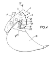
- stops 20 and 21 are arranged outwards relative to the axis of the shaft 17, but this provision can be reversed as shown in the figure 5.
- the tree 17 has two stops 24 and 25 capable, when the tool is locked, of cooperate with two stops 26 and 27 carried by the member 3.
Landscapes
- Engineering & Computer Science (AREA)
- Mechanical Engineering (AREA)
- Mining & Mineral Resources (AREA)
- Civil Engineering (AREA)
- General Engineering & Computer Science (AREA)
- Structural Engineering (AREA)
- Shovels (AREA)
- Earth Drilling (AREA)
- Load-Engaging Elements For Cranes (AREA)
- Forklifts And Lifting Vehicles (AREA)
Claims (4)
- Vorrichtung zum Befestigen eines Werkzeugs am äußeren Ende des Schenkels einer hydraulischen Schaufel oder analogen Organs mittels einer Schnellbefestigung, die durch ein artikuliertes Befestigungsorgan am äußeren Ende des Schenkels gebildet wird und einen Kippfuß umfaßt, der geeignet ist, eine Welle oder Drehzapfen zu greifen, die mit dem Werkzeug fest verbunden sind, dadurch gekennzeichnet, daß das Befestigungsorgan (3) einen Anschlag (12) aufweist, der geeignet ist, mit einem Anschlag (13) zu kooperieren, der an der Peripherie der Welle oder der Drehzapfen (11) des Werkzeugs (2) angeordnete ist, während das Befestigungsorgan auf dem besagten Werkzeug verriegelt ist.
- Vorrichtung gemäß Anspruch 1, dadurch gekennzeichnet, daß der Anschlag (12) eine konkave Kontakfläche (14) aufweist und daß der Anschlag (13) eine konvexe Kontaktfläche (15) aufweist, wobei jede Fläche aus einem Teil der Fläche eines Zylinders besteht, dessen Achse mit der der Welle des Werkzeugs oder der Drehzapfen verschmolzen ist.
- Vorrichtung gemäß Anspruch 1 oder 2, dadurch gekennzeichnet, daß die Welle (17) des Werkzeugs zwei Anschläge (18 - 19 oder 24 - 25) aufweist, die, wenn das Werkzeug in verriegelter Position ist, geeignet sind, mit den zwei von dem Organ (3) getragenen Anschlägen, (20 - 21 oder 26 - 27) zu kooperieren.
- Vorrichtung gemäß Ansprüchen 1 bis 3, dadurch gekennzeichnet, daß die einerseits von der Welle (17) getragenen Anschläge und die andererseits von dem Befestigungsorgan (3) getragenen Anschläge einander diametral entgegengesetzt sind.
Applications Claiming Priority (4)
| Application Number | Priority Date | Filing Date | Title |
|---|---|---|---|
| FR9411631 | 1994-09-29 | ||
| FR9411631A FR2725223B1 (fr) | 1994-09-29 | 1994-09-29 | Perfectionnements aux dispositifs pour fixer un outil a l'extremite du bras d'une pelle hydraulique ou analogue |
| FR9506566A FR2725224B1 (fr) | 1994-09-29 | 1995-06-02 | Perfectionnements aux dispositifs pour fixer un outil a l'extremite du bras d'une pelle hydraulique ou analogue |
| FR9506566 | 1995-06-02 |
Publications (2)
| Publication Number | Publication Date |
|---|---|
| EP0704577A1 EP0704577A1 (de) | 1996-04-03 |
| EP0704577B1 true EP0704577B1 (de) | 2000-02-09 |
Family
ID=26231431
Family Applications (1)
| Application Number | Title | Priority Date | Filing Date |
|---|---|---|---|
| EP95401790A Expired - Lifetime EP0704577B1 (de) | 1994-09-29 | 1995-07-28 | Schnellkupplung zum Befestigen der Arbeitswerkzeuge an einem Baggerausleger |
Country Status (6)
| Country | Link |
|---|---|
| EP (1) | EP0704577B1 (de) |
| AT (1) | ATE189726T1 (de) |
| DE (1) | DE69514973T2 (de) |
| DK (1) | DK0704577T3 (de) |
| ES (1) | ES2144588T3 (de) |
| FR (1) | FR2725224B1 (de) |
Families Citing this family (6)
| Publication number | Priority date | Publication date | Assignee | Title |
|---|---|---|---|---|
| FR2749332B1 (fr) * | 1996-05-30 | 1998-07-03 | Morin Freres | Dispositif pour fixer un outil a l'extremite du bras d'une pelle mecanique |
| FR2760029A1 (fr) * | 1997-02-24 | 1998-08-28 | Case France | Dispositif d'accrochage a une barre, et bras de manipulation d'outil le comportant |
| DE102005056505B3 (de) * | 2005-11-28 | 2007-02-08 | Robert Riedlberger | Zentriervorrichtung für Schnellwechselvorrichtungen |
| DE102017000852B4 (de) * | 2017-01-31 | 2020-11-05 | Markus Riedlberger | Sicherheitsvorrichtung gegen unbeabsichtigtes Herausfallen von Werkzeugen aus einer Schnellwechselvorrichtung |
| DE102017130437A1 (de) * | 2017-12-19 | 2019-06-19 | Oilquick Deutschland Gmbh | Schnellwechsler, Adapter und Schnellwechselsystem |
| DE102017130436A1 (de) * | 2017-12-19 | 2019-06-19 | Oilquick Deutschland Gmbh | Adapter, Schnellwechsler und Schnellwechselsystem |
Family Cites Families (4)
| Publication number | Priority date | Publication date | Assignee | Title |
|---|---|---|---|---|
| BE791834A (nl) * | 1971-12-01 | 1973-03-16 | Verachtert Antonius P | Graafmachine |
| IT1058122B (it) * | 1975-06-21 | 1982-04-10 | Orenstein & Koppel Ag | Dispositivo di cambio rapido per le attrezzature di lavoro di escavatori idraulici |
| FR2657596B1 (fr) * | 1990-01-26 | 1992-04-24 | Morin Freres | Dispositif pour fixer un godet, ou analogue, a l'extremite du bras d'un chargeur. |
| DE9204711U1 (de) * | 1992-04-05 | 1992-07-16 | Eisenwerke Kaiserslautern Gmbh, 6750 Kaiserslautern | Schnellwechselvorrichtung für Baumaschinen |
-
1995
- 1995-06-02 FR FR9506566A patent/FR2725224B1/fr not_active Expired - Fee Related
- 1995-07-28 DK DK95401790T patent/DK0704577T3/da active
- 1995-07-28 AT AT95401790T patent/ATE189726T1/de active
- 1995-07-28 EP EP95401790A patent/EP0704577B1/de not_active Expired - Lifetime
- 1995-07-28 DE DE69514973T patent/DE69514973T2/de not_active Expired - Lifetime
- 1995-07-28 ES ES95401790T patent/ES2144588T3/es not_active Expired - Lifetime
Also Published As
| Publication number | Publication date |
|---|---|
| DE69514973T2 (de) | 2000-07-27 |
| EP0704577A1 (de) | 1996-04-03 |
| DK0704577T3 (da) | 2000-07-24 |
| FR2725224A1 (fr) | 1996-04-05 |
| DE69514973D1 (de) | 2000-03-16 |
| ATE189726T1 (de) | 2000-02-15 |
| ES2144588T3 (es) | 2000-06-16 |
| FR2725224B1 (fr) | 1997-04-18 |
Similar Documents
| Publication | Publication Date | Title |
|---|---|---|
| EP1129259B1 (de) | Schnellkupplungsvorrichtung zur befestigung eines werkzeugs am ende des laderauslegers oder dgl | |
| EP0779951B1 (de) | Fernbedienbarer karabinerhaken, zum festmachen eines taues | |
| EP0438931B1 (de) | Vorrichtung zum Verbinden einer Schaufel, oder dergleichen, am Auslegerende eines Laders | |
| EP0704577B1 (de) | Schnellkupplung zum Befestigen der Arbeitswerkzeuge an einem Baggerausleger | |
| FR2697207A1 (fr) | Crochet d'attelage pour le bras inférieur d'un dispositif d'attelage à trois points d'un tracteur. | |
| EP0787422B1 (de) | Mähmaschine | |
| FR2701047A1 (fr) | Système universel de liaison pour la solidarisation d'un accessoire, notamment d'un godet ou d'une benne, au bras articulé d'un engin de travaux publics. | |
| CA3150811C (fr) | Ensemble de couplage securise d'un outil sur un bras de travail d'un engin de travaux publics a fonctionnement ameliore | |
| FR2725223A1 (fr) | Perfectionnements aux dispositifs pour fixer un outil a l'extremite du bras d'une pelle hydraulique ou analogue | |
| EP0404620B1 (de) | Schlepparm mit selbstpositionierendem Gelenkhaken und damit ausgerüstetes Fahrzeug | |
| EP1587991B1 (de) | Vorrichtung zur einstellung eines am ende eines baggerarms oder der gleichen befestigten werkzeugs | |
| EP0358541A1 (de) | Hub- und Verriegelungsvorrichtung für eine Last oder einen Behälter auf einem Fahrzeug | |
| EP0810330B1 (de) | Vorrichtung zum Befestigen eines Werkzeugs am Ende eines Armes eines Schaufelbaggers | |
| FR2694316A1 (fr) | Chargeur-excavateur-élévateur. | |
| EP2010720B1 (de) | Vorrichtung zur verbindung eines werkzeugs mit dem ausleger einer maschine, wie zum beispiel einem hydraulikbagger | |
| EP1477615A1 (de) | Vorrichtung zur Kupplung eines Werkzeugs an eine Auslegerspitze einer Maschine, sowie einen hydraulischen Bagger. | |
| FR2491901A3 (fr) | Crochet de securite | |
| CA2364936A1 (fr) | Dispositif de prehension et ensemble pour transformer un bras telescopique d'excavatrice en bras d'excavation et de prehension | |
| FR2892752A1 (fr) | Dispositif de verrouillage securise d'un tampon ou couvercle a un cadre, notamment de regard de chaussee | |
| FR2785951A1 (fr) | Attache rapide pour fixer un outil a l'extremite du bras d'un chargeur ou analogue | |
| FR2633022A1 (fr) | Pivot demontable, notamment pour le montage articule d'instruments sur des engins de travaux publics, et moyens d'arret pour un tel pivot | |
| EP1449805B1 (de) | Greifer für Hebevorrichtung | |
| FR2479124A1 (fr) | Dispositif permettant l'equipement de tracteurs agricoles pour la sylviculture | |
| FR2784086A1 (fr) | Dispositif de prehenseur auto-serrant pour la manutention de charges | |
| FR2565640A1 (fr) | Dispositif d'accrochage automatique |
Legal Events
| Date | Code | Title | Description |
|---|---|---|---|
| PUAI | Public reference made under article 153(3) epc to a published international application that has entered the european phase |
Free format text: ORIGINAL CODE: 0009012 |
|
| 17P | Request for examination filed |
Effective date: 19960116 |
|
| AK | Designated contracting states |
Kind code of ref document: A1 Designated state(s): AT BE CH DE DK ES FR GB IT LI NL SE |
|
| 17Q | First examination report despatched |
Effective date: 19980707 |
|
| GRAG | Despatch of communication of intention to grant |
Free format text: ORIGINAL CODE: EPIDOS AGRA |
|
| GRAG | Despatch of communication of intention to grant |
Free format text: ORIGINAL CODE: EPIDOS AGRA |
|
| GRAH | Despatch of communication of intention to grant a patent |
Free format text: ORIGINAL CODE: EPIDOS IGRA |
|
| GRAH | Despatch of communication of intention to grant a patent |
Free format text: ORIGINAL CODE: EPIDOS IGRA |
|
| GRAA | (expected) grant |
Free format text: ORIGINAL CODE: 0009210 |
|
| AK | Designated contracting states |
Kind code of ref document: B1 Designated state(s): AT BE CH DE DK ES FR GB IT LI NL SE |
|
| REF | Corresponds to: |
Ref document number: 189726 Country of ref document: AT Date of ref document: 20000215 Kind code of ref document: T |
|
| REG | Reference to a national code |
Ref country code: CH Ref legal event code: EP |
|
| REF | Corresponds to: |
Ref document number: 69514973 Country of ref document: DE Date of ref document: 20000316 |
|
| ITF | It: translation for a ep patent filed | ||
| REG | Reference to a national code |
Ref country code: CH Ref legal event code: NV Representative=s name: BOVARD AG PATENTANWAELTE |
|
| REG | Reference to a national code |
Ref country code: ES Ref legal event code: FG2A Ref document number: 2144588 Country of ref document: ES Kind code of ref document: T3 |
|
| EN | Fr: translation not filed | ||
| GBT | Gb: translation of ep patent filed (gb section 77(6)(a)/1977) |
Effective date: 20000616 |
|
| REG | Reference to a national code |
Ref country code: DK Ref legal event code: T3 |
|
| EN4 | Fr: notification of non filing translation in an earlier bopi is erroneous | ||
| PLBE | No opposition filed within time limit |
Free format text: ORIGINAL CODE: 0009261 |
|
| STAA | Information on the status of an ep patent application or granted ep patent |
Free format text: STATUS: NO OPPOSITION FILED WITHIN TIME LIMIT |
|
| 26N | No opposition filed | ||
| REG | Reference to a national code |
Ref country code: GB Ref legal event code: IF02 |
|
| REG | Reference to a national code |
Ref country code: FR Ref legal event code: CL |
|
| REG | Reference to a national code |
Ref country code: CH Ref legal event code: PFA Owner name: SOCIETE A RESPONSABILITE LIMITEE : MORIN FRERES Free format text: SOCIETE A RESPONSABILITE LIMITEE : MORIN FRERES#LIEUDIT "LES BRETECHES"#F-45740 LAILLY EN VAL (FR) -TRANSFER TO- SOCIETE A RESPONSABILITE LIMITEE : MORIN FRERES#LIEUDIT "LES BRETECHES"#F-45740 LAILLY EN VAL (FR) |
|
| PGFP | Annual fee paid to national office [announced via postgrant information from national office to epo] |
Ref country code: DK Payment date: 20110708 Year of fee payment: 17 |
|
| PGFP | Annual fee paid to national office [announced via postgrant information from national office to epo] |
Ref country code: AT Payment date: 20110731 Year of fee payment: 17 Ref country code: SE Payment date: 20110722 Year of fee payment: 17 |
|
| REG | Reference to a national code |
Ref country code: SE Ref legal event code: EUG |
|
| REG | Reference to a national code |
Ref country code: AT Ref legal event code: MM01 Ref document number: 189726 Country of ref document: AT Kind code of ref document: T Effective date: 20120728 |
|
| REG | Reference to a national code |
Ref country code: DK Ref legal event code: EBP |
|
| PG25 | Lapsed in a contracting state [announced via postgrant information from national office to epo] |
Ref country code: SE Free format text: LAPSE BECAUSE OF NON-PAYMENT OF DUE FEES Effective date: 20120729 |
|
| PG25 | Lapsed in a contracting state [announced via postgrant information from national office to epo] |
Ref country code: AT Free format text: LAPSE BECAUSE OF NON-PAYMENT OF DUE FEES Effective date: 20120728 |
|
| PG25 | Lapsed in a contracting state [announced via postgrant information from national office to epo] |
Ref country code: DK Free format text: LAPSE BECAUSE OF NON-PAYMENT OF DUE FEES Effective date: 20120731 |
|
| PGFP | Annual fee paid to national office [announced via postgrant information from national office to epo] |
Ref country code: CH Payment date: 20140715 Year of fee payment: 20 Ref country code: DE Payment date: 20140711 Year of fee payment: 20 Ref country code: NL Payment date: 20140630 Year of fee payment: 20 |
|
| PGFP | Annual fee paid to national office [announced via postgrant information from national office to epo] |
Ref country code: FR Payment date: 20140604 Year of fee payment: 20 Ref country code: GB Payment date: 20140717 Year of fee payment: 20 Ref country code: ES Payment date: 20140725 Year of fee payment: 20 |
|
| PGFP | Annual fee paid to national office [announced via postgrant information from national office to epo] |
Ref country code: IT Payment date: 20140714 Year of fee payment: 20 |
|
| PGFP | Annual fee paid to national office [announced via postgrant information from national office to epo] |
Ref country code: BE Payment date: 20140730 Year of fee payment: 20 |
|
| REG | Reference to a national code |
Ref country code: DE Ref legal event code: R071 Ref document number: 69514973 Country of ref document: DE |
|
| REG | Reference to a national code |
Ref country code: CH Ref legal event code: PL |
|
| REG | Reference to a national code |
Ref country code: GB Ref legal event code: PE20 Expiry date: 20150727 |
|
| PG25 | Lapsed in a contracting state [announced via postgrant information from national office to epo] |
Ref country code: GB Free format text: LAPSE BECAUSE OF EXPIRATION OF PROTECTION Effective date: 20150727 |
|
| REG | Reference to a national code |
Ref country code: ES Ref legal event code: FD2A Effective date: 20151104 |
|
| PG25 | Lapsed in a contracting state [announced via postgrant information from national office to epo] |
Ref country code: ES Free format text: LAPSE BECAUSE OF EXPIRATION OF PROTECTION Effective date: 20150729 |