EP0704695B1 - Dispositif d'éclairage pour un appareil d'observation ou un équipement de prise de vue d'images - Google Patents
Dispositif d'éclairage pour un appareil d'observation ou un équipement de prise de vue d'images Download PDFInfo
- Publication number
- EP0704695B1 EP0704695B1 EP95306947A EP95306947A EP0704695B1 EP 0704695 B1 EP0704695 B1 EP 0704695B1 EP 95306947 A EP95306947 A EP 95306947A EP 95306947 A EP95306947 A EP 95306947A EP 0704695 B1 EP0704695 B1 EP 0704695B1
- Authority
- EP
- European Patent Office
- Prior art keywords
- light
- section
- illumination
- half mirror
- optical path
- Prior art date
- Legal status (The legal status is an assumption and is not a legal conclusion. Google has not performed a legal analysis and makes no representation as to the accuracy of the status listed.)
- Expired - Lifetime
Links
Images




Classifications
-
- G—PHYSICS
- G01—MEASURING; TESTING
- G01B—MEASURING LENGTH, THICKNESS OR SIMILAR LINEAR DIMENSIONS; MEASURING ANGLES; MEASURING AREAS; MEASURING IRREGULARITIES OF SURFACES OR CONTOURS
- G01B11/00—Measuring arrangements characterised by the use of optical techniques
- G01B11/30—Measuring arrangements characterised by the use of optical techniques for measuring roughness or irregularity of surfaces
-
- G—PHYSICS
- G01—MEASURING; TESTING
- G01N—INVESTIGATING OR ANALYSING MATERIALS BY DETERMINING THEIR CHEMICAL OR PHYSICAL PROPERTIES
- G01N21/00—Investigating or analysing materials by the use of optical means, i.e. using sub-millimetre waves, infrared, visible or ultraviolet light
- G01N21/84—Systems specially adapted for particular applications
- G01N21/88—Investigating the presence of flaws or contamination
- G01N21/8806—Specially adapted optical and illumination features
Definitions
- the present invention relates to a lighting device for an observation/image pickup apparatus suitable for observing or picking up an image of the surface of a specimen sample.
- the present invention relates to a lighting device for an observation/image pickup apparatus for lighting the surface of a section to be observed (hereinafter referred to as "observed section") of a specimen sample by means of laterally projected lights, deflected oblique light, vertically projected light, or light composed of laterally projected light and vertically projected light as required, or by means of laterally projected light or vertically projected light individually.
- Observation apparatus and image pickup apparatus conventionally used in the art, for example as shown in US-A-4,930,851, are each generally constructed such that a lighting head or an image pickup head, having a light projecting means for illumination incorporated therein, is arranged opposite to the surface of an observed section of a specimen sample to light the observed section and/or obtain an image or an enlarged image of its surface.
- An observation apparatus allows the direct observation of the image thus obtained, whereas the image pickup apparatus is adapted to display the image on a TV monitor, thereby allowing indirect observation of the observed section.
- illumination of the surface of the observed section of the specimen sample with light is carried out by illuminating the surface of the observed section with only oblique light, which is directed obliquely from a side surface of the observed section (or light mainly consisting of so-called laterally projected light), or light illuminating the observed section with only parallel rays directed vertically from a flat surface of the observed section opposite to the surface of the observed section (or light mainly consisting of so-called vertically projected light).
- US-A-4,127,318 describes a lighting device comprising a lens tube having a cylindrical barrel with an illumination light and a half mirror disposed at a predetermined angle with respect to a central optical axis.
- the half mirror comprises an annular part and a central part and the device also includes an image pickup optical system with an objective lens located below the half mirror and also an annular converging lens.
- Lighting techniques using light primarily consisting of laterally projected light or vertically projected light fail to permit the roughness to be precisely observed, particularly when a plane surface section of the specimen sample has a relatively fine roughness. In order to eliminate this problem, it could be considered to combine both lighting techniques. Unfortunately, such a combination can render the apparatus quite complex.
- the present invention has been made in view of the foregoing disadvantages of the prior art.
- a lighting device for an observation/image pickup apparatus which is capable of permitting a surface of an observed section of a specimen sample to be satisfactorily illuminated for observation with any one of: laterally projected light in an entire circumferential direction, deflected oblique light in a partial circumferential direction, vertically projected light, and light composed of vertically projected light and laterally projected light selected as desired, irrespective of whether a relatively fine roughness is present on the surface of the observed section of the specimen sample, in order to provide a lighted image of the surface which can be readily observed in the same visual field while maintaining a simplified structure for the device.
- a lighting device for an observation/image pickup apparatus is provided.
- the lighting device for an observation/image pickup apparatus comprising a lens tube including a cylindrical barrel, the cylindrical barrel including an illumination light introducing section which permits illumination light to be introduced into the lens tube; a half mirror member disposed in the cylindrical barrel, the half mirror member facing the illumination light introducing section and disposed at a predetermined angle with respect to a central optical axis; an annular mirror section at a peripheral portion of the half mirror member; a half mirror section at a central portion of the half mirror member; an image pickup optical system arranged below the half mirror member and including an objective lens arranged so as to correspond positionally to this half mirror section along the central optical axis; an annular converging lens arranged below the half mirror member and positionally corresponding to the annular mirror section; characterised in that the device further comprises an illumination switching cylinder disposed in the lens tube, the illumination switching cylinder being rotatable and surrounding the half mirror member about the central optical axis, and a converging guide member below the image pickup optical system and annular converging lens, the converging guide
- any one of the illumination control slit members for laterally projected light, deflected oblique light, vertically projected light, and light composed of laterally projected light and vertically projected light can be selected to face the illumination light introducing section, in order to convert the illumination light introduced into the illumination light introducing section into any desired one of laterally projected light, deflected oblique light, vertically projected light, and light composed of laterally projected light and vertically projected light, resulting in the surface of the observed section of the specimen sample being illuminated with the converted light.
- illumination light introduced into the illumination light introducing section is converted into laterally projected light through the illumination control slit member, so that the surface of the observed section of the specimen sample may be independently illuminated with the light in the entire circumferential direction or section.
- illumination light introduced into the illumination light introducing section is converted into deflected oblique light in a semi-circumferential section through the illumination control slit member, so that the surface of the observed section of the specimen sample may be independently illuminated with the light in a semi-circumferential direction or section.
- illumination light introduced into the illumination light introducing section is converted into corresponding vertically projected light through the illumination control slit member, so that the surface of the observed section of the specimen sample may be independently illuminated with the light in a vertical direction.
- the illumination control slit member for light composed of laterally projected light and vertically projected light is permitted to face the illumination light introducing section, is converted into corresponding laterally projected light in an entire circumferential direction and vertically projected light in a vertical direction through the illumination control slit member, so that the surface of the observed section of the specimen sample may be independently illuminated in a direction composed of both light in an entire circumferential direction and light in a vertical direction.
- the illumination control slit members each include a focusing optical system for rendering rays of illumination light introduced through the illumination light introducing section parallel to each other.
- This construction permits rays of each of the selected laterally projected light, deflected oblique light, vertically projected light, and composed light, to be rendered parallel, so that the surface of the observed section of the specimen sample may be more effectively illuminated.
- the illumination control slit member for laterally projected light is provided at only a portion thereof corresponding to the annular mirror section with a focusing lens acting as a light permeable section.
- This construction permits rays of illumination light introduced into the illumination light introducing section to pass through the focusing lens of the illumination control slit member for laterally projected light, resulting in the light rays being parallel to each other, so that laterally projected light exhibiting the directionality desired for the illumination light may be readily obtained.
- the illumination control slit member for deflected oblique light is provided at only a portion thereof corresponding to a part of the annular mirror section with a focusing lens acting as a light permeable section.
- This construction permits rays of illumination light introduced into the illumination light introducing section to pass through the focusing lens of the illumination control slit member for deflected oblique light, to provide partially corresponding parallel rays, so that deflected oblique light exhibiting directionality desired for illumination light may be readily obtained.
- the illumination control slit member for vertically projected light is provided at only that portion corresponding to a part of the half mirror section, with a focusing lens acting as a light permeable section.
- This construction permits rays of illumination light introduced into the illumination light introducing section to pass through the focusing lens of the illumination control slit member for vertically projected light, resulting in the light rays being rendered parallel to each other, so that vertically projected light exhibiting the directionality desired for the illumination light may be readily obtained.
- the illumination control slit member for light composed of laterally projected light and vertically projected light is provided at only that portion corresponding to each of the annular mirror section and the half mirror section, with a focusing lens acting as a light permeable section.
- This construction permits rays of illumination light introduced into the illumination light introducing section to pass through the focusing lens of the illumination control slit member for the composed light corresponding to each of the annular mirror section and half mirror section, resulting in the light rays being rendered parallel to each other, so that light composed of laterally projected light and vertically projected light each exhibiting the directionality desired for the illumination light may be readily obtained.
- any one of the illumination control slit members for laterally projected light, deflected oblique light, vertically projected light, and light composed of laterally projected light and vertically projected light can be selected to face the illumination light introducing section, in order to convert illumination light introduced into the illumination light introducing section into any desired one of laterally projected light, deflected oblique light, vertically projected light, and light composed of laterally projected light and vertically projected light, resulting in the surface of the observed section of the specimen sample being illuminated with the converted light.
- the illumination control slit member for deflected oblique light is permitted to face the illumination light introducing section, the illumination control slit member may be rotated to vary the angular range of illumination by deflected oblique light.
- illumination control slit member for laterally projected light When the illumination control slit member for laterally projected light is permitted to face the illumination light introducing section, illumination light introduced into the illumination light introducing section is converted into laterally projected light through the illumination control slit member, so that the surface of the observed section of the specimen sample may be independently illuminated with the light in the entire circumferential direction.
- illumination control slit member for deflected oblique light When the illumination control slit member for deflected oblique light is permitted to face the illumination light introducing section, illumination light introduced into the illumination light introducing section is converted into deflected oblique light in a semi-circumferential direction through the illumination control slit member, so that the surface of the observed section of the specimen sample may be independently illuminated with the light in a semi-circumferential direction.
- illumination control slit member for vertically projected light When the illumination control slit member for vertically projected light is permitted to face the illumination light introducing section, illumination light introduced into the illumination light introducing section is converted into corresponding vertically projected light through the illumination control slit member, so that the surface of the observed section of the specimen sample may be independently illuminated with the light in a vertical direction.
- illumination control slit member for light composed of laterally projected light and vertically projected light is permitted to face the illumination light introducing section, illumination light introduced into the illumination light introducing section is converted into corresponding laterally projected light in the entire circumferential direction and vertically projected light in a vertical direction through the illumination control slit member, so that the surface of the observed section of the specimen sample may be independently illuminated in a direction composed of both light in the entire circumferential direction and light in a vertical direction.
- an alternative lighting device for an observation/image pickup apparatus includes a lens tube including a cylindrical barrel provided on one side of its outer periphery with an illumination light introducing section which permits illumination light to be introduced into the lens tube.
- the cylindrical barrel is provided with a half mirror member which faces the illumination light introducing section at a predetermined angle on a central optical axis.
- the half mirror member includes, on a peripheral portion thereof, an annular mirror section.
- the half mirror member includes, at a central portion thereof, a half mirror section.
- the lighting device also includes an observation optical system arranged below the half mirror member including an objective lens arranged so as to correspond positionally to the half mirror section on the central optical a converging guide member including an outside an inside optical path and an optical path switching damper arranged on the upper light-guide side of the half mirror member opposite to the annular mirror section for carrying out switching between a downwardly extending outside optical path and an inside optical path.
- the outside optical path is provided with an objective opening facing a surface of an observed section of a specimen sample and the inside optical path is provided with a lower opening directed toward the specimen sample.
- the optical path switching damper is switched toward the inside optical path to permit illumination light introduced into the outside optical path to be applied in the form or laterally projected light from the inner periphery of the objective opening to the specimen sample.
- the optical path switching damper is switched toward the outside optical path to permit illumination light introduced into the inside optical path to be applied in the form of vertically projected light from the lower opening to the specimen sample.
- switching of the optical path switching damper toward the inside optical path permits illumination light introduced into the outside optical path to be converted into laterally projected light for illuminating the surface of the observed section of the specimen sample.
- switching of the optical path switching damper toward the outside optical path permits illumination light introduced into the inside optical path to be converted into vertically projected light for illuminating the surface of the observed section of the specimen sample.
- FIGURES 1 to 3, as well as FIGURES 4 to 7, show a first embodiment of a lighting device for an observation/image pickup apparatus according to the present invention.
- FIGURES 8 to 10 show a second embodiment of a lighting device for an observation/image pickup apparatus according to the present invention
- FIGURES 11 and 12 show a third embodiment of a lighting device for an observation/image pickup apparatus according to the present invention.
- a lighting device of each of the illustrated embodiments is applied to an image pickup apparatus, however, it is to be understood that the present invention is likewise applicable to an observation apparatus, i.e., for directly observing the illuminated specimen.
- FIGURES 1 to 3 First, the first embodiment of the present invention shown in FIGURES 1 to 3 will be described while concurrently secondarily describing the second embodiment shown in FIGURE 8 to 10 (which respectively correspond to FIGURE 1 to 3).
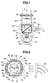
- FIGURE 1 is a vertical sectional view schematically showing an image pickup apparatus according to the first embodiment of the lighting device according to the present invention.
- FIGURE 2 is an enlarged cross sectional view schematically showing an illumination switching cylinder incorporated in the lighting device of FIGURE 1.
- FIGURES 3(a) to 3(d) each show a built-in illumination control slit member of the focusing optical system incorporated in the illumination switching cylinder shown in FIGURE 2, wherein FIGURE 3(a) is a front elevation view showing an illumination control slit member for laterally projected light (hereinafter referred to as “laterally projected light slit member”).
- FIGURE 3(b) is a front elevation view showing an illumination control slit member for deflected oblique light (hereinafter referred to as “deflected oblique light slit member”).
- FIGURE 3(c) is a front elevation view showing an illumination control slit member for vertically projected light (hereinafter referred to as “vertically projected light slit member”).
- FIGURE 3(d) is a front elevation view showing an illumination control slit member for light composed of laterally projected light and vertically projected light (hereinafter referred to as “composed light slit member”).
- FIGURE 8 and 9 are a vertical sectional view and an enlarged cross sectional view showing the second embodiment of the lighting device of the present invention, which respectively correspond to FIGURES 1 and 2.
- FIGURES 10(a) to 10(d) also show the second embodiment, and respectively correspond to FIGURES 3(a) to 3(d).
- the image pickup apparatus includes a lens tube 11 which is provided, with a cylindrical barrel 12.
- the cylindrical barrel 12 is provided on a part or one side of an outer periphery thereof, with an illumination light introducing section 13 which permits illumination light on an incident optical axis B transmitted through an optical fiber bundle 13a to be introduced therethrough into the lens tube 11.
- the cylindrical barrel 12 is provided therein with a half mirror member 14.
- the half mirror member 14 faces the illumination light introducing section 13 while being kept oblique at an angle of 45 degrees on a central optical axis A.
- the half mirror member 14 includes, on a peripheral portion of a lower side (i,e., the downwardly facing surface) thereof, with an annular mirror section 15 and on a central portion thereof with a half mirror section 16.
- the annular mirror section 15 is separately formed on the half mirror member 14 by deposition.
- the lens tube 11 includes an illumination switching cylinder 31 arranged around the half mirror member 14 in the cylindrical barrel 12 so as to surround the half mirror member 14.
- the illumination switching cylinder 31 is provided with a switching operation ring 32, and rotates about the central optical axis A, as described in detail hereinafter.
- the lens tube 11 is provided therein with an image pickup optical system 17 which is arranged below the half mirror member 14 and which includes an objective lens arranged so as to positionally correspond to the half mirror section 16 of the half mirror member 14 along the central optical axis A.
- the lens tube 11 is provided therein with an annular converging lens 18, which is arranged so as to define an outer peripheral section of the image pickup optical system 17, and to positionally correspond to the annular mirror section 15.
- the lens tube 11 includes a converging guide member 19 connected to or mounted on a lower portion of the cylindrical barrel 12 in a manner to be positioned below the image pickup optical system 17 and below annular converging lens 18, and so as to at least partially surround the image pickup optical system 17.
- the converging guide member 19 includes an objective opening 20 which faces a surface of an observed section of a specimen sample C, and which is provided on an inner peripheral surface thereof with an annular converging step 21 so as to positionally correspond to the annular converging lens 18.
- the lens tube 11 also includes a focus mechanism 22 arranged on the cylindrical barrel 12 so as to constitute an upper section of the lens tube 11, which focus mechanism 22 may be constructed in a manner conventionally known in the art.
- the focus mechanism 22 is adapted to be actuated for focusing by means of a focus operation ring 23.
- the focus mechanism 22 is provided therein with a CCD element 24, which is arranged so as to be positioned on the central optical axis A, and includes a variable magnifying mechanism 25 which may be constructed in a manner conventionally known in the art.
- the illumination switching cylinder 31, equipped with the switching operation ring 32, as shown in FIGURES 2 and 3(a) to 3(d) or FIGURES 9 and 10(a) to 10(d), includes a holding cylinder 33 arranged so as to be rotated about the central optical axis A and around the half mirror member 14 by means of the switching operation ring 32.
- the holding cylinder 33 is preferably rotated intermittently by 90 degrees (i.e., the slit members are at 90 degree intervals).
- the holding cylinder 33 is divided into four sections at angular intervals of 90 degrees in a circumferential direction thereof, in which a laterally projected light slit member 41, a deflected oblique light slit member 51, a vertically projected light slit member 61 and a composed light slit member 71 are fitted, respectively.
- the slit members 41, 51, 61 and 71 each have a focusing optical system incorporated therein for permitting rays of illumination light introduced therein through the illumination light introducing section 13 to be parallel to each other.
- a selective switching operation of the switching operation ring 32 permits the slit members 41, 51, 61 and 71 to selectively alternately face the illumination light introducing section 13.
- the laterally projected light slit member 41 as shown in FIGURE 3(a) or 10(a), is provided (at a portion thereof corresponding to an entire circumference of the annular mirror section 15 of the half mirror member 14) with a focusing lens 42 of an annular shape for focusing illumination light, so that the annular focusing lens 42 acts as a light permeable section of the slit member 41, while the remaining part of the slit member 41 is a light non-permeable section 43.
- the deflected oblique light slit member 51 is provided (at a portion thereof corresponding to a part of a circumference of the annular mirror section 15 of the half mirror member 14) with a focusing lens 52 having a semi-annular shape for focusing illumination light, so that the focusing lens 52 acts as a light permeable section of the slit member 51, while the remaining part of the slit member 51 is a light non-permeable section 53.
- the focusing lens 52 is arranged so as to positionally correspond to a right-hand half of the annular mirror section 15.
- a rotation operation ring 54 is provided for rotating the focusing lens 52 about the incident optical axis B as desired.
- the vertically projected light slit member 61 is provided at a portion thereof corresponding to the half mirror section 16 of the half mirror member 14 with a focusing lens 62 for focusing illumination light, so that the focusing lens 62 acts as a light permeable section, while the remaining part of the slit member 61 is a light non-permeable section 63.
- the composed light slit member 71 is provided at a portion thereof corresponding to an entire circumference of each of the annular mirror section 15 and half mirror section 16 of the half mirror member 14 with a focusing lens 72 for focusing illumination light, so that the focusing lens 72 acts as a light permeable section while the remaining part of the slit member 71 is a light non-permeable section 73.
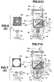
- FIGURE 4(a) is a vertical sectional view showing an optical path of each of the illumination light and the image pickup light obtained when a lighting mode provided by laterally projected light (hereinafter referred to as "first lighting mode” or “first illumination mode”) is applied to the image pickup apparatus of the first embodiment.
- FIGURE 4(b) is a schematic view showing the relationship between the laterally projected light slit member selected for the first lighting mode and each of the illumination light and the image pickup light with respect to the specimen sample.
- the first lighting mode is carried out by a selective switching operation of the switching operation ring 32 so that the laterally projected light slit member 41 of the illumination switching cylinder 31 faces the illumination light introducing section 13.
- rays of illumination light (a), introduced into the illumination light introducing section 13, are permitted to pass through only the focusing lens 42 being annular, of the laterally projected light slit member 41, resulting in the light rays being rendered parallel to each other.
- the light is then reflected by the annular mirror section 15 formed on the entire periphery of the half mirror member 14, to thereby be downwardly directed, in the direction of the central optical axis A.
- the rays are permitted to pass through the annular converging lens is and are introduced from the annular converging step 21 into the converging guide member 19, to thereby provide laterally projected light a 1 discharged in an entire or full circumferential direction from the objective opening 20, so that an observed section of the specimen sample C is illuminated with the light a 1 .
- the observed section of the specimen sample C is independently illuminated with the laterally projected light a 1 in the entire or full circumferential direction.
- the image pickup light b 1 reflected by the observed section of the specimen sample C is guided from the objective opening 20 through the image pickup optical system 17 to the half mirror section 16 of the half mirror member 14, with the light then introduced into the CCD element 24.
- the CCD element 24 converts the image pickup light b 1 into an electrical signal, which is then displayed on an image plane of a TV monitor (not shown). This provides an image of the observed section of the specimen sample C illuminated with the laterally projected light a 1 as desired, or the image illuminated in the first lighting made is readily and effectively observed.
- FIGURE 5(a) is a vertical sectional view showing an optical path of each of the illumination light, and the image pickup light obtained when a lighting mode provided by deflected oblique light (hereinafter referred to as "second lighting mode” or “second illumination mode”) is applied to the image pickup apparatus of the first embodiment.
- FIGURE 5(b) is a schematic view showing an illumination range of the illumination light by a deflected oblique light slit member selected for the second lighting mode shown in FIGURE 5(a)
- FIGURE 5(c) is a schematic view showing the relationship between the deflected oblique light slit member selected for the second lighting mode and each of the illumination light and the image pickup light with respect to the specimen sample.
- the second lighting mode is carried out by a selective switching operation of the switching operation ring 32 so that the deflected oblique light slit member 51 of the illumination switching cylinder 31 faces the illumination light introducing section 13.
- rays of illumination light (a), introduced into the illumination light introducing section 13, are permitted to pass through only the focusing lens 52 being semi-annular, corresponding to the right-hand half of the deflected oblique light slit member 51, resulting in the light rays being parallel to each other.
- the light is then reflected by the right-hand half of the annular mirror section 15 of the half mirror member 14, to thereby be downwardly directed, in the direction of central optical axis A.
- the rays are then permitted to pass through the right-hand half of the annular converging lens 18, and are introduced from the annular converging step 21 into the converging guide member 19, to thereby provide deflected oblique light a 2 extending over a semicircumference on a right-hand half of the objective opening 20.
- the observed section of the specimen sample C is independently illuminated with the deflected oblique light a 2 in a semicircumferential or right-hand half direction.
- the image pickup light b 2 reflected by the observed section of the specimen sample C is likewise guided from the objective opening 20 through the image pickup optical system 17 to the half mirror section 16 of the half mirror member 14, with the light then introduced into the CCD element 24.
- the CCD element 24 converts the image pickup light b 2 into an electrical signal, which is then displayed on a TV monitor (not shown). This provides an image of the observed section of the specimen sample C illuminated with the deflected oblique light a 2 as desired, or the image illuminated in the second lighting modes is readily and effectively observed.
- lighting of the image pickup apparatus of the second embodiment is carried out in a way different from that of the first embodiment, due to the arrangement of the rotation operation ring 54 (Fig. 10b). More particularly, a selective rotation operation of the rotation operation ring 54, as desired, permits an angular range of illumination or lighting by the deflected oblique light a 2 to be varied about the central optical axis A for observation.
- FIGURE 6(a) is a vertical sectional view showing an optical path of each of the illumination light and the image pickup light obtained when a lighting mode provided by vertically projected light (hereinafter referred to as "third lighting mode” or “third illumination mode”) is applied to the image pickup apparatus of FIGURE 1.
- FIGURE 6(b) is a schematic view showing the relationship between the vertically projected light slit member selected for the third lightning mode and each of the illumination light and the image pickup light with respect to the specimen sample.
- the third lighting mode is carried out by a selective switching operation of the switching operation ring 32, such that the vertically projected light slit member 61 of the illumination switching cylinder 31 faces the illumination light introducing section 13.
- rays of illumination light (a), introduced into the illumination light introducing section 13, are permitted to pass through only the focusing lens 62 formed at the control portion of the vertically projected light slit member 61, resulting in the light rays being the light rays parallel to each other.
- the light is then reflected by the half mirror section 16 of the half mirror member 14, to thereby be downwardly directed, in the direction of the central optical axis A.
- the rays are permitted to pass through the image pickup optical system 17, to thereby provide vertically projected light a 3 from the objective opening 20, so that the observed section of the specimen sample C is illuminated with the light a 3 .
- the observed section of the specimen sample C is independently illuminated with the laterally projected light a 3 , projected in a vertical direction.
- image pickup light b 3 reflected by the observed section of the specimen sample C is guided from the objective opening 20 through the image pickup optical system 17 to the half mirror section 16 of the half mirror member 14 and then introduced into the CCD element 24.
- the CCD element 24 converts the image pickup light b 3 into an electrical signal, which is then displayed on a TV monitor (not shown). This provides an image of the observed section of the specimens sample C illuminated with the vertically projected light a 3 as desired, or the image illuminated in the third lighting mode is readily and effectively observed.
- FIGURE 7(a) is a vertical sectional view schematically showing an optical path of each of the illumination light and the image pickup light obtained when a lighting mode provided by light composed of laterally projected light and vertically projected light (hereinafter referred to as "fourth lighting mode” or “fourth illumination mode”) is applied to the image pickup apparatus of FIGURE 1.
- FIGURE 7(b) is a schematic view showing the relationship between the composed light slit member selected for the fourth lightning mode and each of the illumination light and the image pickup light with respect to the specimen sample.
- the fourth lighting mode is carried out by a selective switching operation of the switching operation ring 32, so that the composed light slit member 71 of the illumination switching cylinder 31 faces the illumination light introducing section 13.
- rays of illumination light (a), introduced into the illumination light introducing section 13 are permitted to pass through only the annular section of the focusing lens 72 of the composed light slit member 71, resulting in the light rays being parallel to each other.
- the light rays are then reflected by the annular mirror section 15 formed on the entire downwardly facing periphery of the half mirror member 14, to thereby be downwardly directed in the form of laterally projected light a 4a in the direction of the central optical axis A, as in the first illumination mode described above.
- the rays are permitted to pass through the central section of the focusing lens 72 of the composed light slit member 71, resulting in the light rays being parallel to each other.
- the rays of the laterally projected light a 4a are permitted to pass through the annular converging lens 18, and are then introduced from the annular converging step 21 into the converging guide member 19, so that the observed section of the specimen sample C is illuminated with the light a 4a discharged in an entire or full circumferential direction from the objective opening 20.
- rays of the vertically projected light a 4b are permitted to pass through the image pickup optical system 17, so that the observed section of the specimen sample C is illuminated with the light a 4b vertically discharged through the objective opening 20.
- the observed section of the specimen sample C is independently illuminated with the laterally projected light a 4a in the whole or full circumferential direction and with the vertically projected light a 4b in the vertical direction. In other words, it is independently irradiated with light a 4b composed of the laterally projected light a 4a and vertically projected light a 4b .
- the image pickup light b 4 reflected by the observed section of the specimen sample C is guided from the objective opening 20 through the image pickup optical system 17 to the half mirror section 16 of the half mirror member 14, and is then introduced into the CCD element 24.
- the CCD element 24 converts the image pickup light b 4 into an electrical signal, which is then displayed on a TV monitor (not shown). This results in an image of the observed section of the specimen sample C illuminated with the light a 4 composed of the laterally projected light a 4a and vertically projected light a 4b as desired, or the image illuminated in the fourth lighting mode is readily and effectively observed.
- FIGURES 11 and 12 a third embodiment of a lighting device for an observation/image pickup apparatus according to the present invention is illustrated. More specifically, FIGURES 11 and 12 each schematically show an image pickup apparatus to which a lighting device of the third embodiment is applied.
- the lighting device of the third embodiment is applied to an image pickup apparatus as in the first and second embodiments described above. However, it may also be effectively applied to an observation apparatus.
- the lighting device of the third embodiment includes a lens tube 111 which is provided with a cylindrical barrel 112.
- the cylindrical barrel 112 is provided on a part of an outer periphery thereof, with an illumination light introducing section 113 for permitting illumination light on an incident optical axis B transmitted through an optical fiber bundle 113a to be introduced therethrough into the lens tube 111.
- the illumination light introducing section 113 includes a focusing lens 114 for focusing illumination light.
- the focusing lens 114 is formed into an annular shape and is arranged along the incident optical axis B so as to permit only the full annular or circumferential portion of the illumination light introducing section 113 to act as a light permeable section, and the remaining central portion thereof acts as a light non-permeable section 115 for interrupting the illumination light.
- the focusing lens 114 functions to cause rays of illumination light introduced into the illumination light introducing section 113 to be parallel to each other while being kept wholly annular, with the light then guided into the cylindrical barrel 112.
- the cylindrical barrel 112 is provided therein with a half mirror member 116.
- the half mirror member 116 is arranged in a manner to face the illumination light introducing section 113 while being kept oblique at an angle of 45 degrees on a central optical axis A, and is formed on a peripheral portion of a lower side (i.e., the downwardly facing surface) thereof with an annular mirror section 117 and at a central portion thereof with a half mirror section 118.
- the annular mirror section 117 is separately formed on the half mirror member 116 by deposition.
- the lens tube 111 is provided therein with an observation optical system 119 which is arranged below the half mirror member 116 and which includes an objective lens arranged so as to positionally correspond to the half mirror section 118 of the half mirror member 116 along the central optical axis A.
- the lens tube 111 is provided therein with a converging guide member 120 which is arranged below the half mirror member and includes an outside optical path 121, an inside optical path 122 and an optical path switching damper 123 for switching between the outside optical path 121 and the inside optical path 122, which damper 123 is arranged on the upper light introducing surface of the converging guide member so as to be opposite to the annular mirror section 117.
- the converging guide member 120 is formed with an objective opening 124 associated with the downwardly extending outside optical path 121.
- the objective opening 124 is arranged so as to face a surface of an observed section of a specimen sample C on the central optical axis A.
- the converging guide member 120 is formed with a lower opening 125 disposed or arranged to be directed toward the specimen sample C.
- the lens tube 111 also includes a focus mechanism 126 arranged on the cylindrical barrel 112 so as to constitute an upper section of the lens tube 111.
- the focus mechanism 126 is actuated for focusing by means of a focus operation ring 127.
- the focus mechanism 126 is provided therein with a CCD element 128, which is positioned on the central optical axis A and includes a variable magnifying mechanism 129.
- FIGURE 11 is a vertical sectional view showing an optical path of each of the illumination light and the image pickup light obtained when a lighting mode provided by laterally projected light (hereinafter referred to as "fifth lighting mode” or “fifth illumination mode”) is applied to the image pickup apparatus of the third embodiment described above.
- a selective switching operation of the optical path switching damper 123 toward the inside optical path 122 results in the outside optical path 121 of the converging guide member 120 being utilized. Switching of the optical path switching damper 123 toward the inside optical path 122 corresponds to lighting of the specimen sample C by laterally projected light introduced into the outside optical path 121.
- rays of illumination light (a), introduced into the illumination light introducing section 113, are permitted to pass through the focusing lens 114, resulting in the rays being rendered parallel to each other.
- the light is then totally reflected by the annular mirror section 117 of the half mirror member 116, to thereby be guided to an upper light-guide side of the converging guide member 120.
- the rays are introduced into the outside optical path 121, and then are repeatedly reflected by an outer switching surface of the optical path switching damper 123, as well as an inner surface of the outside optical path 121 in the outside optical path 121.
- the rays are projected in the form of laterally projected light a 5 on the observed section of the specimen sample C from a whole or entire circumference of the objective opening 124.
- the observed section of the specimen sample C is independently illuminated with the laterally projected light a 5 in a whole or full circumferential direction.
- image pickup light b 5 reflected by the observed section of the specimen sample C is guided from the objective opening 124 through the observation optical system 119 to the half mirror section 118 of the half mirror member 116 and then introduced into the CCD element 128, so that the CCD element 128 converts the image pickup light b 5 into an electrical signal, which is then displayed on a TV monitor (not shown).
- FIGURE 12 is a vertical sectional view showing an optical path of each of the illumination light and the image pickup light obtained when a lighting mode provided by vertically projected light (hereinafter referred to as "sixth lighting mode” or “sixth illumination mode”) is applied to the image pickup apparatus of the third embodiment described above.
- a selective switching operating of the optical path switching damper 123 toward the outside optical path results in the inside optical path 122 of the converging guide member 120 being utilized.
- Switching of the optical path switching damper 123 toward the outside optical path 121 corresponds to lighting of the specimen sample C by vertically projected light introduced into the inside optical path 122.
- rays of the illumination light (a), introduced into the illumination light introducing section 113 are permitted to pass through the focusing lens 114, resulting in the light rays being rendered parallel to each other.
- the light is then totally reflected by the annular mirror section 117 of the half mirror member 116, to thereby be guided to the upper light-guide side of the converging guide member 120, resulting in the light being introduced into the inside optical path 122.
- the rays are repeatedly reflected by an inner switching surface of the optical path switching damper 123, as well as the inner surface of the inside optical path 122 in the inside optical path 122.
- the rays are projected in the form of vertically projected light a 6 on the observed section of the specimen sample C from an entire circumference of the lower opening 125.
- the observed section of the specimen sample C is independently illuminated with the vertically projected light a 6 in a whole or full circumferential direction.
- image pickup light b 6 reflected by the observed section of the specimen sample C is guided from the objective opening 124 through the observation optical system 119 to the half mirror section 118 of the half mirror member 116 and then introduced into the CCD element 128.
- the CCD element 128 converts the image pickup light b 6 into an electrical signal, which is then displayed on a TV monitor (not shown). This results in an image of the observed section of the specimen sample C illuminated with the vertically projected light a 6 as desired, or the image illuminated in the sixth lighting mode is readily and effectively observed.
- the illumination control slit member is provided with the converging lens for providing parallel rays.
- any desired optical system for rendering rays of illumination light parallel is interposedly arranged between the slit member and the illumination light introducing section, resulting in a light guide slit being substituted for the converging lens.
Landscapes
- Physics & Mathematics (AREA)
- General Physics & Mathematics (AREA)
- Health & Medical Sciences (AREA)
- Life Sciences & Earth Sciences (AREA)
- Chemical & Material Sciences (AREA)
- Analytical Chemistry (AREA)
- Biochemistry (AREA)
- General Health & Medical Sciences (AREA)
- Immunology (AREA)
- Pathology (AREA)
- Microscoopes, Condenser (AREA)
Claims (9)
- Dispositif d'éclairage pour un appareil d'observation/analyse d'images comprenant un tube de lentille (11) incluant un tambour cylindrique (12), le tambour cylindrique (12) incluant une section d'introduction de lumière d'illumination (13) qui permet que la lumière d'illumination soit introduite dans le tube de lentille (11) ; un élément de demi-miroir (14) disposé dans le tambour cylindrique (12), l'élément de demi-miroir (14) faisant face à la section d'introduction de lumière d'illumination (13) et étant disposé suivant un angle prédéterminé par rapport à un axe optique central ; une section de miroir annulaire (15) au niveau d'une partie périphérique de l'élément de demi-miroir (14) ; une section de demi-miroir (16) au niveau d'une partie centrale de l'élément de demi-miroir (14) ; un système optique d'analyse d'images (17) agencé en dessous de l'élément de demi-miroir (14) et incluant une lentille d'objectif agencée de manière à correspondre sur le plan de la position à cette section de demi-miroir (16) le long de l'axe optique central ; une lentille convergente annulaire (18) agencée en dessous de l'élément de demi-miroir (14) et correspondant sur le plan de la position à la section de miroir annulaire (15) ; caractérisé en ce que le dispositif comprend en outre un cylindre de commutation d'illumination (31) disposé dans le tube de lentille (11), le cylindre de commutation d'illumination (31) étant rotatif et entourant l'élément de demi-miroir (14) autour de l'axe optique central, et un élément de guide de convergence (19) en dessous du système optique d'analyse d'images (17) et une lentille convergente annulaire (18), l'élément de guide de convergence (19) étant disposé pour correspondre sur le plan de la position à la lentille convergente annulaire (18) ; l'élément de guide de convergence (19) incluant une ouverture d'objectif (20) faisant face à une surface d'une section observée d'un échantillon spécimen sur l'axe optique central ; le cylindre de commutation d'illumination (31) comportant à sa périphérie une pluralité d'éléments de fente de commande d'illumination (41,51,61,71) pour permettre respectivement qu'une lumière d'illumination soit introduite dans le tube de lentille à travers la section d'introduction de lumière d'illumination pour être convertie de manière sélective en au moins une lumière projetée latéralement, une lumière oblique déviée, une lumière projetée verticalement et une lumière composée d'une lumière projetée latéralement et d'une lumière projetée verticalement ; les éléments de fente de commande d'illumination (41,51,61,71) étant agencés pour faire face de manière sélective à la section d'introduction de lumière d'illumination (13).
- Dispositif d'éclairage suivant la revendication 1, caractérisé en ce que l'élément de fente de commande d'illumination pour une lumière oblique déviée (51) est rotatif et disposé perpendiculairement à un axe optique incident de la section d'introduction de lumière d'illumination (13), de telle sorte que, lorsque l'élément de fente de commande d'illumination pour une lumière oblique déviée (51) est sélectionné, l'élément de fente de commande d'illumination pour une lumière oblique déviée (51) tourne de manière sélective autour de l'axe optique incident de la section d'introduction de lumière d'illumination (13) pour former un angle de lumière oblique déviée par rapport à l'échantillon spécimen.
- Dispositif d'éclairage suivant la revendication 1 ou 2, caractérisé en ce que les éléments de fente de commande d'illumination (41,51,61,71) comprennent chacun un système optique de focalisation (42,52,62,72) pour rendre des rayons de lumière d'illumination introduits à travers la section d'introduction de lumière d'illumination (13) parallèles les uns aux autres.
- Dispositif d'éclairage suivant l'une quelconque des revendications précédentes, caractérisé en ce que l'élément de fente de commande d'illumination pour une lumière projetée latéralement (41) est pourvu d'une lentille de focalisation (42) faisant office de section perméable à la lumière seulement sur une partie de celle-ci correspondant à la section de miroir annulaire (15).
- Dispositif d'éclairage suivant l'une quelconque des revendications précédentes, caractérisé en ce que l'élément de fente de commande d'illumination pour une lumière oblique déviée (51) est pourvu d'une lentille de focalisation (52) faisant office de section perméable à la lumière seulement sur une partie de celle-ci correspondant à une partie la section de miroir annulaire (15).
- Dispositif d'éclairage suivant l'une quelconque des revendications précédentes, caractérisé en ce que l'élément de fente de commande d'illumination pour une lumière projetée verticalement (61) est pourvu d'une lentille de focalisation (62) faisant office de section perméable à la lumière seulement sur une partie de celle-ci correspondant à une partie de la section de demi-miroir (16).
- Dispositif d'éclairage suivant l'une quelconque des revendications précédentes, caractérisé en ce que l'élément de fente de commande d'illumination pour une lumière composée d'une lumière projetée latéralement et d'une lumière projetée verticalement (71) est pourvu d'une lentille de focalisation (72) faisant office de section perméable à la lumière seulement sur une partie de celle-ci correspondant à chaque section de miroir annulaire et chaque section de demi-miroir (16).
- Dispositif d'éclairage pour un appareil d'observation/analyse d'images comprenant un tube de lentille (111) incluant un tambour cylindrique (112), le tambour cylindrique (112) incluant une section d'introduction de lumière d'illumination (113) qui permet que la lumière d'illumination soit introduite dans le tube de lentille (111) ; un élément de demi-miroir (116) disposé dans le tambour cylindrique (112), l'élément de demi-miroir (116) faisant face à la section d'introduction de lumière d'illumination (113) suivant un angle prédéterminé par rapport à un axe optique central ; une section de miroir annulaire (117) au niveau d'une partie périphérique de l'élément de demi-miroir (116), et une section de demi-miroir (118) au niveau d'une partie centrale de l'élément de demi-miroir (116), et un système optique d'observation (119) agencé en dessous de l'élément de demi-miroir (116) et incluant une lentille d'objectif disposée pour correspondre sur le plan de la position à la section de demi-miroir (118) le long de l'axe optique central ; le dispositif étant caractérisé par un élément de guide de convergence (120) incluant un chemin optique extérieur (121), un chemin optique intérieur (122) et un amortisseur de commutation de chemin optique (123) agencé sur un côté de guide de lumière supérieur de l'élément de demi-miroir (116) en face de la section de miroir annulaire (117) pour effectuer une commutation entre le chemin optique extérieur s'étendant vers le bas (121) et le chemin optique intérieur (122) ; le chemin optique extérieur (121) étant pourvu d'une ouverture d'objectif (124) faisant face à une surface d'une section observée d'un échantillon spécimen, et le chemin optique intérieur (122) étant pourvu d'une ouverture inférieure dirigée vers l'échantillon spécimen ; l'amortisseur de commutation de chemin optique (123) étant commuté vers le chemin optique intérieur (122) pour permettre qu'une lumière d'illumination introduite dans le chemin optique extérieur (121) soit appliquée sous la forme d'une lumière projetée latéralement à partir d'une périphérie intérieure de l'ouverture d'objectif (124) vers l'échantillon spécimen et étant commuté vers le chemin optique extérieur (121) pour permettre qu'une lumière d'illumination introduite dans le chemin optique intérieur (122) soit appliquée sous la forme d'une lumière projetée verticalement depuis l'ouverture inférieure vers l'échantillon spécimen.
- Dispositif d'éclairage suivant la revendication 8, caractérisé en ce que la section d'introduction de lumière d'illumination (113) est pourvue d'une lentille de focalisation (114) faisant office de section perméable seulement sur une partie de celle-ci correspondant à la section de miroir annulaire (117) et une section imperméable à la lumière (115) est prévue au niveau de la section d'introduction de lumière d'illumination de manière à correspondre sur le plan de la position à la section de demi-miroir (118).
Applications Claiming Priority (9)
| Application Number | Priority Date | Filing Date | Title |
|---|---|---|---|
| JP259794/94 | 1994-09-30 | ||
| JP6259794A JPH08101128A (ja) | 1994-09-30 | 1994-09-30 | 観察、撮像装置の照明装置 |
| JP25979494 | 1994-09-30 | ||
| JP39414/95 | 1995-02-06 | ||
| JP03941495A JP3642599B2 (ja) | 1995-02-06 | 1995-02-06 | 観察・撮像装置の照明装置 |
| JP3941395 | 1995-02-06 | ||
| JP03941395A JP3642598B2 (ja) | 1995-02-06 | 1995-02-06 | 観察・撮像装置の照明装置 |
| JP39413/95 | 1995-02-06 | ||
| JP3941495 | 1995-02-06 |
Publications (3)
| Publication Number | Publication Date |
|---|---|
| EP0704695A2 EP0704695A2 (fr) | 1996-04-03 |
| EP0704695A3 EP0704695A3 (fr) | 1996-07-17 |
| EP0704695B1 true EP0704695B1 (fr) | 2002-01-16 |
Family
ID=27290130
Family Applications (1)
| Application Number | Title | Priority Date | Filing Date |
|---|---|---|---|
| EP95306947A Expired - Lifetime EP0704695B1 (fr) | 1994-09-30 | 1995-09-29 | Dispositif d'éclairage pour un appareil d'observation ou un équipement de prise de vue d'images |
Country Status (4)
| Country | Link |
|---|---|
| US (1) | US5580162A (fr) |
| EP (1) | EP0704695B1 (fr) |
| KR (1) | KR960011384A (fr) |
| DE (1) | DE69525007T2 (fr) |
Families Citing this family (8)
| Publication number | Priority date | Publication date | Assignee | Title |
|---|---|---|---|---|
| JPH10145567A (ja) * | 1996-11-08 | 1998-05-29 | Canon Inc | 画像読取装置 |
| US20080024794A1 (en) * | 2004-06-04 | 2008-01-31 | Yoko Miyazaki | Semiconductor Surface Inspection Apparatus and Method of Illumination |
| DE102004034957A1 (de) * | 2004-07-16 | 2006-02-02 | Carl Zeiss Jena Gmbh | Anordnung zur mikroskopischen Beobachtung und/oder Detektion und Verwendung |
| EP2515153A1 (fr) * | 2011-04-20 | 2012-10-24 | Braedius Scientific B.V. | Dispositif de microscopie à fond noir |
| JP6393667B2 (ja) * | 2015-09-09 | 2018-09-19 | 株式会社東芝 | 外観検査装置および外観検査方法 |
| US10295476B1 (en) * | 2018-08-14 | 2019-05-21 | Applied Materials Israel Ltd. | System and method for multiple mode inspection of a sample |
| US12222486B2 (en) * | 2020-12-28 | 2025-02-11 | Bioaces (Shanghai) Life Science Co., Ltd | Light source apparatus, microscopic device, optical detection device and optical detection method |
| JP2026507735A (ja) * | 2022-12-20 | 2026-03-05 | ビット グループ フランス | 単一の非コヒーレント光源から発せられるビームを分割することによって蛍光及び散乱を測定する光学フローサイトメータ |
Family Cites Families (8)
| Publication number | Priority date | Publication date | Assignee | Title |
|---|---|---|---|---|
| US2097762A (en) * | 1933-05-26 | 1937-11-02 | Ernst Leitz | Microscope |
| DE2542075A1 (de) * | 1975-09-20 | 1977-07-21 | Leitz Ernst Gmbh | Auflicht-beleuchtungseinrichtung fuer hell- und dunkelfeldbeleuchtung |
| DE3475566D1 (en) * | 1984-05-14 | 1989-01-12 | Ibm Deutschland | Method and device for the inspection of surfaces |
| US4585315A (en) * | 1984-11-13 | 1986-04-29 | International Business Machines Corporation | Brightfield/darkfield microscope illuminator |
| JPH0664238B2 (ja) * | 1985-05-24 | 1994-08-22 | 宏 木村 | 高温顕微鏡 |
| JPH01308527A (ja) * | 1988-06-07 | 1989-12-13 | Sukara Kk | 拡大撮像装置における照明用導光装置 |
| US5220453A (en) * | 1991-02-20 | 1993-06-15 | Luxtec Corporation | Telescopic spectacles with coaxial illumination |
| JP3318347B2 (ja) * | 1992-04-23 | 2002-08-26 | スカラ株式会社 | 観察、撮像装置などの照明装置 |
-
1995
- 1995-09-29 US US08/536,276 patent/US5580162A/en not_active Expired - Fee Related
- 1995-09-29 DE DE69525007T patent/DE69525007T2/de not_active Expired - Fee Related
- 1995-09-29 EP EP95306947A patent/EP0704695B1/fr not_active Expired - Lifetime
- 1995-09-30 KR KR1019950033949A patent/KR960011384A/ko not_active Abandoned
Also Published As
| Publication number | Publication date |
|---|---|
| EP0704695A2 (fr) | 1996-04-03 |
| KR960011384A (ko) | 1996-04-20 |
| DE69525007T2 (de) | 2002-09-26 |
| EP0704695A3 (fr) | 1996-07-17 |
| DE69525007D1 (de) | 2002-02-21 |
| US5580162A (en) | 1996-12-03 |
Similar Documents
| Publication | Publication Date | Title |
|---|---|---|
| KR970009174B1 (ko) | 확대 촬상 장치의 조명용 도광 장치 | |
| EP0183946B1 (fr) | Illumination à fond clair/noir pour des microscopes | |
| EP0371547B1 (fr) | Appareil pour contrôler la surface interne d'un corps | |
| US5820250A (en) | Dark field illuminator ringlight adaptor | |
| EP0704695B1 (fr) | Dispositif d'éclairage pour un appareil d'observation ou un équipement de prise de vue d'images | |
| US4017147A (en) | Comparison microscope | |
| US3637280A (en) | Devices for high-contrast imaging of phase objects in incident-light microscopy | |
| JPH08166514A (ja) | 斜光照明装置 | |
| JPH0593869A (ja) | 顕微鏡の照明装置 | |
| JP3642598B2 (ja) | 観察・撮像装置の照明装置 | |
| JPH08101128A (ja) | 観察、撮像装置の照明装置 | |
| JP3642599B2 (ja) | 観察・撮像装置の照明装置 | |
| US4501476A (en) | Device for checking the light source adjustment in an incident light microscope | |
| JP2000232564A (ja) | 対象物の不均一照度を補償する光学系 | |
| JP4339553B2 (ja) | 共焦点顕微鏡 | |
| JPH0297909A (ja) | 暗視野照明装置 | |
| JPH06313708A (ja) | 皮膚表面観察装置 | |
| JP3178592B2 (ja) | 共焦点顕微鏡 | |
| EP0541808A1 (fr) | Instrument d'imagerie permettant l'observation d'un objet grossi | |
| JPH10274714A (ja) | 観察・撮像装置の偏射光照射角度切替え機構付き照明装置 | |
| JPH04136807A (ja) | 落射照明装置 | |
| JPH10246857A (ja) | 斜光照明装置 | |
| KR200174671Y1 (ko) | 화상 현미경 | |
| JPH05303042A (ja) | ビデオマイクロスコープ用照明装置 | |
| JP2003043368A (ja) | 顕微鏡 |
Legal Events
| Date | Code | Title | Description |
|---|---|---|---|
| PUAI | Public reference made under article 153(3) epc to a published international application that has entered the european phase |
Free format text: ORIGINAL CODE: 0009012 |
|
| AK | Designated contracting states |
Kind code of ref document: A2 Designated state(s): DE GB NL |
|
| PUAL | Search report despatched |
Free format text: ORIGINAL CODE: 0009013 |
|
| RHK1 | Main classification (correction) |
Ipc: G02B 21/10 |
|
| AK | Designated contracting states |
Kind code of ref document: A3 Designated state(s): DE GB NL |
|
| 17P | Request for examination filed |
Effective date: 19960909 |
|
| RAP1 | Party data changed (applicant data changed or rights of an application transferred) |
Owner name: SCALAR CORPORATION |
|
| 17Q | First examination report despatched |
Effective date: 20000619 |
|
| GRAG | Despatch of communication of intention to grant |
Free format text: ORIGINAL CODE: EPIDOS AGRA |
|
| GRAG | Despatch of communication of intention to grant |
Free format text: ORIGINAL CODE: EPIDOS AGRA |
|
| GRAH | Despatch of communication of intention to grant a patent |
Free format text: ORIGINAL CODE: EPIDOS IGRA |
|
| GRAH | Despatch of communication of intention to grant a patent |
Free format text: ORIGINAL CODE: EPIDOS IGRA |
|
| GRAA | (expected) grant |
Free format text: ORIGINAL CODE: 0009210 |
|
| REG | Reference to a national code |
Ref country code: GB Ref legal event code: IF02 |
|
| AK | Designated contracting states |
Kind code of ref document: B1 Designated state(s): DE GB NL |
|
| REF | Corresponds to: |
Ref document number: 69525007 Country of ref document: DE Date of ref document: 20020221 |
|
| PG25 | Lapsed in a contracting state [announced via postgrant information from national office to epo] |
Ref country code: GB Free format text: LAPSE BECAUSE OF NON-PAYMENT OF DUE FEES Effective date: 20020929 |
|
| PLBE | No opposition filed within time limit |
Free format text: ORIGINAL CODE: 0009261 |
|
| STAA | Information on the status of an ep patent application or granted ep patent |
Free format text: STATUS: NO OPPOSITION FILED WITHIN TIME LIMIT |
|
| 26N | No opposition filed | ||
| PG25 | Lapsed in a contracting state [announced via postgrant information from national office to epo] |
Ref country code: NL Free format text: LAPSE BECAUSE OF NON-PAYMENT OF DUE FEES Effective date: 20030401 Ref country code: DE Free format text: LAPSE BECAUSE OF NON-PAYMENT OF DUE FEES Effective date: 20030401 |
|
| GBPC | Gb: european patent ceased through non-payment of renewal fee |
Effective date: 20020929 |