EP0704936B1 - Dichtungsanordnung - Google Patents
Dichtungsanordnung Download PDFInfo
- Publication number
- EP0704936B1 EP0704936B1 EP95112246A EP95112246A EP0704936B1 EP 0704936 B1 EP0704936 B1 EP 0704936B1 EP 95112246 A EP95112246 A EP 95112246A EP 95112246 A EP95112246 A EP 95112246A EP 0704936 B1 EP0704936 B1 EP 0704936B1
- Authority
- EP
- European Patent Office
- Prior art keywords
- male
- housing
- female
- elements
- seal member
- Prior art date
- Legal status (The legal status is an assumption and is not a legal conclusion. Google has not performed a legal analysis and makes no representation as to the accuracy of the status listed.)
- Expired - Lifetime
Links
- 238000007789 sealing Methods 0.000 title claims description 34
- 230000008878 coupling Effects 0.000 claims description 11
- 238000010168 coupling process Methods 0.000 claims description 11
- 238000005859 coupling reaction Methods 0.000 claims description 11
- 238000005452 bending Methods 0.000 claims description 5
- XLYOFNOQVPJJNP-UHFFFAOYSA-N water Substances O XLYOFNOQVPJJNP-UHFFFAOYSA-N 0.000 description 14
- 230000003405 preventing effect Effects 0.000 description 8
- 230000007246 mechanism Effects 0.000 description 5
- 238000003825 pressing Methods 0.000 description 4
- 230000008859 change Effects 0.000 description 3
- 230000005489 elastic deformation Effects 0.000 description 3
- 238000004519 manufacturing process Methods 0.000 description 3
- 238000010276 construction Methods 0.000 description 2
- 230000013011 mating Effects 0.000 description 2
- 238000000034 method Methods 0.000 description 2
- 229920003002 synthetic resin Polymers 0.000 description 2
- 239000000057 synthetic resin Substances 0.000 description 2
- 230000000694 effects Effects 0.000 description 1
- 239000002184 metal Substances 0.000 description 1
- 230000009467 reduction Effects 0.000 description 1
Images



Classifications
-
- H—ELECTRICITY
- H01—ELECTRIC ELEMENTS
- H01R—ELECTRICALLY-CONDUCTIVE CONNECTIONS; STRUCTURAL ASSOCIATIONS OF A PLURALITY OF MUTUALLY-INSULATED ELECTRICAL CONNECTING ELEMENTS; COUPLING DEVICES; CURRENT COLLECTORS
- H01R13/00—Details of coupling devices of the kinds covered by groups H01R12/70 or H01R24/00 - H01R33/00
- H01R13/46—Bases; Cases
- H01R13/52—Dustproof, splashproof, drip-proof, waterproof, or flameproof cases
- H01R13/5202—Sealing means between parts of housing or between housing part and a wall, e.g. sealing rings
-
- H—ELECTRICITY
- H01—ELECTRIC ELEMENTS
- H01R—ELECTRICALLY-CONDUCTIVE CONNECTIONS; STRUCTURAL ASSOCIATIONS OF A PLURALITY OF MUTUALLY-INSULATED ELECTRICAL CONNECTING ELEMENTS; COUPLING DEVICES; CURRENT COLLECTORS
- H01R13/00—Details of coupling devices of the kinds covered by groups H01R12/70 or H01R24/00 - H01R33/00
- H01R13/62—Means for facilitating engagement or disengagement of coupling parts or for holding them in engagement
- H01R13/621—Bolt, set screw or screw clamp
- H01R13/6215—Bolt, set screw or screw clamp using one or more bolts
-
- Y—GENERAL TAGGING OF NEW TECHNOLOGICAL DEVELOPMENTS; GENERAL TAGGING OF CROSS-SECTIONAL TECHNOLOGIES SPANNING OVER SEVERAL SECTIONS OF THE IPC; TECHNICAL SUBJECTS COVERED BY FORMER USPC CROSS-REFERENCE ART COLLECTIONS [XRACs] AND DIGESTS
- Y10—TECHNICAL SUBJECTS COVERED BY FORMER USPC
- Y10S—TECHNICAL SUBJECTS COVERED BY FORMER USPC CROSS-REFERENCE ART COLLECTIONS [XRACs] AND DIGESTS
- Y10S277/00—Seal for a joint or juncture
- Y10S277/911—Seal combined with nominal motion transmitting device
Definitions
- the present invention relates to a waterproof connector for connecting a pair of housings by means of coupling members such as a bolt and a nut.
- FIG. 8 One example of the known waterproof connectors is shown in FIG. 8.
- the waterproof connector 1 is assembled as follows.
- a male housing 4 mounting unillustrated male terminal fittings is fixed in a mount hole 3 of a panel 2 by means of an unillustrated mounting means such that an opening of a hood (receptacle) 5 of the male housing 4 is in conformity with the mount hole 3.
- a female housing 6 mounting unillustrated female terminal fittings is slightly inserted into the receptacle 5 through the mount hole 3 from the side of the panel 2 opposite from the male housing 4.
- one bolt 7 mounted on the female housing 6 is spirally engaged with an unillustrated nut mounted on the male housing 4, the female housing 6 moves closer to the male housing 4, with the result that the male and female terminal fittings are engaged.
- a seal member 8 is mounted on the female housing 6 in order to prevent entry of water from the female housing 6 to the male housing 4 through the mount hole 3 of the panel 2.
- the seal member 8 comes into close contact with the surface of the panel 2 while undergoing an elastic deformation. As a result, water entering between the female housing 6 and the mount hole 3 is generally prevented from further entering the male housing 4.
- the female housing 6 is brought into such a curved state where it is more spaced apart from the panel 2 as it extends more distant from the bolt 7.
- a sealing force acting between the seal member 8 and the panel 2 becomes weaker as the seal member 8 extends more distant from the bolt 7.
- a water entry preventing function of the seal member 8 becomes nonuniform, thereby making water more likely to leak into the housings.
- a method as disclosed in Japanese Unexamined Utility Model Publication No. 4-69874 may be adopted to solve the above problem. Specifically, four bolts are mounted at respective corners of a terminal fitting mounting area. The respective bolts are turned together by a gear mechanism so that the entire housing is forcibly and uniformly moved closer to the mating housing.
- the use of an increased number of bolts and the gear mechanism leads not only to a larger size housing, but also to an increased production cost resulting from the more complicated construction.
- the invention was developed in view of the above problem, and an object thereof is to prevent a reduction in a water entry preventing function resulting from a deflection of a housing without using a large size mechanism and making the housing larger.
- the coupling means when the two elements are moved closer to each other by the coupling means, at least one element (on its corresponding surface) is deformed in such a curved manner that it is more distant from the mating element as it extends more distant from the coupling means.
- the deformation of the at least one element causes the seal member to be deformed and curved in the same direction.
- either the seal member or the deformed element(s) (or both) is/are shaped such that the seal element is entirely and uniformly brought into contact with the surfaces to be sealed. In other words, the sealing force is made uniform over the sealing area.
- the curve of the seal member caused by the deformation is reverse of the curve of the seal member.
- the sealing surface of the seal member undergoes a change of state: from a curved state where it is closer to the sealed surface as it extends more distant from the coupling means, to a state where it can entirely and uniformly be brought into close contact with the surfaces to be sealed.
- the curved shape of the sealing surface of the seal member is formed by making the seal member thicker as it extends more distant from the coupling means.
- the curved shape of the sealing surface is formed by making the thickness of the seal member constant and by preforming the element(s) such that its(their) surface(s) provide(s) for a uniform sealing force after being deformed.
- FIGS. 1 to 5 a first embodiment according to the invention is described with respect to FIGS. 1 to 5.
- a waterproof connector 10 is mounted on a panel P, and includes a male housing 20 mounted in advance on the panel P and a female housing 30 to be assembled with the already mounted male housing 20.
- the male housing 20 is of a synthetic resin, and has a vertically relatively long rectangular front surface.
- a receptacle 21 projects along a periphery of the front surface of the male housing 20.
- a plurality of cavities 22 for accommodating unillustrated male terminal fittings extend from a front end surface of the receptacle 21 to a rear end surface of the male housing 20.
- the plurality of cavities 22 are arranged one over another in the vertical direction except for a portion of the male housing 20 located slightly lower than a vertical center of the male housing.
- a projection 23 projecting forward from the front end surface of the receptacle 21 where no cavities 22 are formed is formed with a through hole 24 extending in a direction in which the housings 20 and 30 are engaged (i.e., a lateral direction in FIG. 1).
- a nut 25 mounted from a lateral side of the male housing 20 is fixed such that it neither moves in a longitudinal axis direction nor rotates about a longitudinal axis.
- the male housing 20 is secured on the right surface of the panel P in FIG. 1 by engaging projections 26 formed at upper and lower edges of an opening of the receptacle 21 with a mount hole H of the panel P.
- the female housing 30 is of a synthetic resin, and has such a vertically relatively long rectangular cross-section that it can be fitted into the receptacle 21.
- a plurality of cavities 32 for accommodating unillustrated female terminal fittings extend from a front end surface of the female housing 30 to a rear end surface thereof.
- the plurality of cavities 32 are arranged one over another in the vertical direction except for a portion of the male housing 30 located slightly lower than a vertical center of the male housing.
- a recess 33 engageable with the projection 23 of the male housing 20 is formed on the front end surface of the female housing 30 where no cavities 32 are formed.
- a bolt hole 34 which is a through hole extending to the rear end surface of the female housing 30, is coaxially formed with the nut 25.
- a bolt 35 which forms a coupling member 15 together with the nut 25 is inserted into the bolt hole 34.
- An external thread portion 35B spirally engageable with the nut 25 is formed at the leading end of a shaft 35A of the bolt 35. In a position of the shaft 35A contiguous with a head 35C, there is formed a pressing portion 35D engageable with a rear opening edge of the bolt hole 34.
- the pressing portion 35D has a larger diameter than the shaft 35A, thereby forming a stepped portion at the boundary between the pressing portion 35D and the shaft 35A. Further, the head 35C is formed with a jaw portion 35E engageable from behind with a grommet cover 38 to be described later.
- a grommet holder 36 having openings 36A and opening 36B in conformity with the bolt hole 34 and a cylindrical portion 37B of a grommet 37, respectively, is mounted at a rear end of the female housing 30.
- the grommet 37 having an opening 37A in conformity with the bolt hole 34 is mounted on the outer surface of the grommet holder 36 such that it covers the entire rear end surface of the female housing 30.
- a bundle of unillustrated wires connected with the female terminal fittings extending backward of the female housing 30 from the cavities 32 are inserted into the cylindrical portion 37B formed in the grommet 37.
- the grommet cover 38 of metal having openings 38A and 38B in conformity with the bolt hole 34 and the cylindrical portion 37B of the grommet 37, respectively, are mounted at the outside of the grommet 37.
- the grommet 37 is of an elastically deformable rubber.
- the periphery of the grommet 37 acts as a seal portion 40 which is sealably in contact with the left (rear) surface PA of the panel P to be sealed in an assembled state of the housings 20 and 30.
- the seal portion 40 is adapted to prevent entry of water from the female housing 30 to the male housing 20 through a clearance between the mount hole H of the panel P and the female housing 30.
- a lateral edge of the seal portion 40 extending in the vertical direction has a nonuniform thickness, which is a dimension in the engaging direction of the housings 20 and 30 (a lateral direction in FIGS. 3 and 4).
- the thickness of the seal portion 40 is smallest at a height corresponding to the position of the bolt 35, and gradually increases as the seal portion extends more upward and downward from this height.
- the rear surface of the seal portion 40 having a variable thickness and coming into contact with the grommet cover 38 is flat (a left surface in FIGS. 3 and 4), so that it is in parallel with a sealed surface PA of the panel P when the female housing 30 is positioned in a posture to be assembled with the male housing 20 (see FIG. 3, where the panel P is shown twice in order to demonstrate parallelism).
- a sealing surface of the seal portion 40 (a right surface in FIGS. 3 and 4) facing the sealed surface PA forms a concave surface with respect to the sealed surface PA such that it is closer to the sealed surface PA as it extends more toward its upper and lower ends, i.e., as it extends more distant from the bolt 35.
- the horizontal upper and lower edges of the seal portion 40 have a uniform thickness as shown in FIG. 5 as they are closer to the bolt 35 than the upper and lower ends.
- the male and female terminal fittings are engaged as the male and female housings 20 and 30 are assembled.
- an engagement resisting force which prevents an approach of the radially outer portions of the housings 20 and 30 and, hence, counteracts an approach of the radially inner portions (portions close to the bolt 35) of the housings 20 and 30.
- This engagement resisting force acts on the housings 20 and 30.
- the male housing 20 is secured on the panel P, only the female housing 30 is subjected to the engagement resisting force.
- the portion of the female housing 30 close to the bolt 35 is forcibly moved toward the male housing 20 since a fastening force of the bolt 35 directly acts thereon.
- the portions of the female housing 30 above and below the bolt 35 are also moved toward the male housing 20 due to rigidity of the female housing 30, the grommet holder 36 and the grommet cover 38 (however, not by the same extent as close to the bolt 35).
- a larger bending moment due to the engagement resisting force acts in positions of the female housing 30 more distant from the bolt 35, i.e., in positions closer to the upper and lower edges of the female housing 30, thereby curving the female housing 30 away from the male housing 20.
- the seal portion 40 is deformed and curved in a similar direction.
- the seal portion 40 is formed reversely of the curve of the sealing surface 40A. Accordingly, the sealing surface 40A undergoes a change of state: from a curved state where it is closer to the sealed surface PA of the panel P as it extends more toward its upper and lower edges away from the bolt 35, to a flat state where it is flat and parallel with the sealed surface PA.
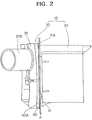
- the sealing surface 40A comes into close contact with the panel P while undergoing an elastic deformation (see FIG. 2).
- the seal portion 40 is uniformly and strongly in close contact with the sealed surface PA over its entire sealing surface 40A, with the result that entry of water from the female housing 30 to the male housing 20 through a clearance between the mount hole H of the panel P and the female housing 30 can be prevented.
- the sealing surface 40A of the seal portion 40 has a curved shape, taking into consideration that the female housing 30 is caused to curve due to the engagement resistance between the male and female terminal fittings. Accordingly, the seal portion 40 exhibits a high water entry preventing function in the assembled state of the housings 20 and 30.
- the connector according to the embodiment does not meet problems of a larger size and an increased production cost resulting from the sue of a complicated mechanism.
- a waterproof connector of the second embodiment differs from that of the first embodiment in the shape of the female housing and the seal portion. Since the other construction is same as in the first embodiment, no description is given thereto with regards the structure, the operation and the effect thereof by identifying like elements by like reference numerals.
- a thickness of a seal portion 60 in a direction in which housings 20 and 50 are engaged is uniform along the vertical direction.
- the surface of a grommet cover 58 in contact with the seal portion 60 has such a curved shape that it is closer to the panel P as it extends more toward its upper and lower edges from the height of the bolt 35, i.e., away from the bolt 35.
- a sealing surface 60A of the seal portion 60 (a right surface in FIGS. 6 and 7) facing a sealed surface PA has such a curved shape that it is closer to the sealed surface PA as it extends more distant from the bolt 35.
- the sealing surface 60A undergoes a change of state: from a curved state where it is closer to the sealed surface PA of the panel P as it extends more toward its upper and lower edges away from the bolt 35, to a flat state where it is flat and parallel with the sealed surface PA. In this state, the sealing surface 60A comes into close contact with the panel P while undergoing an elastic deformation (see FIG. 6).
- the sealing surface 60A is entirely, uniformly and strongly in close contact with the sealed surface PA, with the result that entry of water from the female housing 50 to the male housing 20 through a clearance between a mount hole H of the panel P and the female housing 30 can be prevented.
- the sealing surface 60A has a curved shape, taking into consideration that the female housing 50 is caused to curve due to the engagement resistance between male and female terminal fittings. Accordingly, the seal portion 60 exhibits a high water entry preventing function in the assembled state of the housings 20 and 50.
- the present invention is not limited to the above described and illustrated embodiments.
- the invention may be embodied in a variety of other forms.
Landscapes
- Connector Housings Or Holding Contact Members (AREA)
Claims (9)
- Dichtungsanordnung mit zwei Elementen (P, 38) und einem Dichtungselement (40), welches zwischen zwei Flächen (PA, 38C) der zwei Elemente zum Dichten von diesen angeordnet ist, wobei die zwei Elemente (P, 38) durch Verbindungsmittel (15) gegeneinander gedrückt werden, die zwischen ihnen wirken und ein Biegemoment auf wenigstens eines (38) der zwei Elemente (P, 38) aufbringen, so daß die korrespondierende(n) Fläche(n) (38C) verformt wird/werden, dadurch gekennzeichnet, daß das Dichtungselement (40) derart geformt ist, daß es die Verformung der Fläche(n) (38C) kompensiert.
- Dichtungsanordnung mit zwei Elementen (P, 58) und einem Dichtungselement (60), welches zwischen zwei Flächen (PA, 58C) der zwei Elemente zum Dichten von diesen angeordnet ist, wobei die zwei Elemente (P, 58) durch Verbindungsmittel (15) gegeneinander gedrückt werden, die zwischen ihnen wirken und ein Biegemoment auf wenigstens eines (58) der zwei Elemente aufbringen, so daß die korrespondierende(n) Fläche(n) (58C) verformt wird/werden, dadurch gekennzeichnet, daß wenigstens eines (58) der zwei Elemente derart gestaltet ist, daß die Dichtungskraft gleichmäßig gemacht wird.
- Dichtungsanordnung gemäß Anspruch 1 oder 2, bei welcher die Elemente (P, 38; P, 58) Teile eines wasserdichten Verbinders (10) mit einem Stekkerabschnitt (20, P) und einem Buchsenabschnitt (30, 36, 37, 38; 50, 58) sind, welche miteinander dichtend verbunden werden sollen.
- Dichtungsanordnung gemäß Anspruch 3, bei welcher das Dichtungselement (40; 60) zwischen einer Platte P des Steckerabschnittes (20, P) und einem Dichtungsabdeckelement (38; 58) des Buchsenabschnittes (30, 36, 37, 38; 50, 58) angeordnet ist.
- Dichtungsanordnung gemäß Anspruch 3 oder 4, bei welcher das Dichtungselement (40; 60) an einem der Stecker- und Buchsenabschnitte vorgesehen ist.
- Dichtungsanordnung gemäß Anspruch 1, bei welcher das Dichtungselement (40) derart gestaltet ist, daß seine Dicke mit dem Abstand von dem Verbindungsmittel (15) in wenigstens einer Richtung zunimmt.
- Dichtungsanordnung gemäß Anspruch 2, bei welcher das Dichtungselement (60) derart gestaltet ist, daß seine Dicke konstant ist.
- Dichtungsanordnung gemäß einem der Ansprüche 3 bis 5, bei welcher die Stecker- und Buchsenabschnitte durch eine Schrauben/Mutter-Anordnung (35, 25) verbunden werden, die an dem Stecker- bzw. Buchsenabschnitt vorgesehen sind.
- Dichtungsanordnung gemäß einem der Ansprüche 1 bis 8, bei welcher das Verbindungsmittel (15) ungefähr in der Mitte der Flächen (PA, 38C; PA, 58C), welche zu dichten sind, angeordnet ist.
Applications Claiming Priority (2)
| Application Number | Priority Date | Filing Date | Title |
|---|---|---|---|
| JP6258919A JP2907733B2 (ja) | 1994-09-27 | 1994-09-27 | 防水コネクタ |
| JP258919/94 | 1994-09-27 |
Publications (2)
| Publication Number | Publication Date |
|---|---|
| EP0704936A1 EP0704936A1 (de) | 1996-04-03 |
| EP0704936B1 true EP0704936B1 (de) | 1998-11-11 |
Family
ID=17326862
Family Applications (1)
| Application Number | Title | Priority Date | Filing Date |
|---|---|---|---|
| EP95112246A Expired - Lifetime EP0704936B1 (de) | 1994-09-27 | 1995-08-03 | Dichtungsanordnung |
Country Status (4)
| Country | Link |
|---|---|
| US (1) | US5607169A (de) |
| EP (1) | EP0704936B1 (de) |
| JP (1) | JP2907733B2 (de) |
| DE (1) | DE69505937T2 (de) |
Families Citing this family (2)
| Publication number | Priority date | Publication date | Assignee | Title |
|---|---|---|---|---|
| JP6490571B2 (ja) * | 2015-12-14 | 2019-03-27 | タイコエレクトロニクスジャパン合同会社 | 封止構造 |
| JP2020087843A (ja) * | 2018-11-30 | 2020-06-04 | 矢崎総業株式会社 | コネクタの取付構造及びコネクタ |
Family Cites Families (11)
| Publication number | Priority date | Publication date | Assignee | Title |
|---|---|---|---|---|
| FR2075758A5 (de) * | 1970-01-20 | 1971-10-08 | Yazaki Corp | |
| US3837657A (en) * | 1971-12-22 | 1974-09-24 | Farnam F Co | Beaded gasket and method of using same |
| US3913927A (en) * | 1973-10-03 | 1975-10-21 | Federal Mogul Corp | Sealing boundary gasket for sealing between metal members that are held together by bolts |
| JPS58152151A (ja) * | 1982-03-08 | 1983-09-09 | Daihatsu Motor Co Ltd | オイルパン |
| US4688809A (en) * | 1985-11-26 | 1987-08-25 | Cummins Engine Company, Inc. | Gasket for internal combustion engine |
| DE8704509U1 (de) * | 1987-03-26 | 1987-05-27 | Richard Hirschmann Gmbh & Co, 73728 Esslingen | Elastomerdichtung |
| JPH0438468Y2 (de) * | 1987-12-09 | 1992-09-09 | ||
| JPH03138439A (ja) * | 1989-10-20 | 1991-06-12 | Ketsuto & Ketsuto:Kk | 金属ガスケット |
| JPH089912Y2 (ja) | 1990-10-30 | 1996-03-21 | 矢崎総業株式会社 | ねじ締めコネクタ |
| US5090713A (en) * | 1990-12-24 | 1992-02-25 | Johnson Roy E | Elastomeric gasket for sealing a glass fiber reinforced cover to a vault |
| JP2602385B2 (ja) * | 1992-01-16 | 1997-04-23 | 矢崎総業株式会社 | 多極コネクタ |
-
1994
- 1994-09-27 JP JP6258919A patent/JP2907733B2/ja not_active Expired - Fee Related
-
1995
- 1995-08-03 EP EP95112246A patent/EP0704936B1/de not_active Expired - Lifetime
- 1995-08-03 DE DE69505937T patent/DE69505937T2/de not_active Expired - Lifetime
- 1995-08-16 US US08/516,013 patent/US5607169A/en not_active Expired - Lifetime
Also Published As
| Publication number | Publication date |
|---|---|
| US5607169A (en) | 1997-03-04 |
| DE69505937D1 (de) | 1998-12-17 |
| JP2907733B2 (ja) | 1999-06-21 |
| EP0704936A1 (de) | 1996-04-03 |
| JPH0896885A (ja) | 1996-04-12 |
| DE69505937T2 (de) | 1999-05-27 |
Similar Documents
| Publication | Publication Date | Title |
|---|---|---|
| EP0655802B1 (de) | Dichtungsanordnung für schalltafelmontierte elektrische Verbinder | |
| EP0677894B1 (de) | Abdichtungsvorrichtung und Herstellverfahren eines wasserdichten Stecker | |
| EP2433338B1 (de) | Wasserverschlussstopfen und konnektor mit dem wasserverschlussstopfen | |
| US7094098B2 (en) | Connector for apparatus | |
| US5823807A (en) | Connector assembly with mechanism for confirmation of fitting of connector housing and method of attaching connector housing | |
| EP0599329A2 (de) | Kabeldichtung für wasserdichte elektrische Verbinder | |
| US5890932A (en) | Connector | |
| US6089909A (en) | Connector | |
| US5766039A (en) | Waterproof connector with pressing holes in seal member | |
| JPH08180928A (ja) | 防水コネクタ | |
| US6185869B1 (en) | Door glass run for a motor vehicle | |
| US6254428B1 (en) | Waterproof structure for connector | |
| JPH08306439A (ja) | コネクタのパネルへの取付構造 | |
| US5660555A (en) | Waterproof connector and method for assembling the same | |
| JP2531970Y2 (ja) | 車両用灯具のコネクタ保持構造 | |
| US6835094B2 (en) | Connector and a connector assembly | |
| US4822294A (en) | Sealing grommet assembly for wiring harness | |
| US5586854A (en) | Connector fastening nut and bolt-nut fastened connector | |
| US5154645A (en) | Bulb socket | |
| EP0704936B1 (de) | Dichtungsanordnung | |
| JP2002373737A (ja) | 機器用シールドコネクタ | |
| US11469539B2 (en) | Seals for a flat flexible conductor in an electrical connector assembly | |
| US6332797B1 (en) | Waterproof connector | |
| US5630731A (en) | Waterproof connector | |
| CN1094670C (zh) | 灯头插座和其生产方法 |
Legal Events
| Date | Code | Title | Description |
|---|---|---|---|
| PUAI | Public reference made under article 153(3) epc to a published international application that has entered the european phase |
Free format text: ORIGINAL CODE: 0009012 |
|
| 17P | Request for examination filed |
Effective date: 19951030 |
|
| AK | Designated contracting states |
Kind code of ref document: A1 Designated state(s): DE GB |
|
| GRAG | Despatch of communication of intention to grant |
Free format text: ORIGINAL CODE: EPIDOS AGRA |
|
| 17Q | First examination report despatched |
Effective date: 19980129 |
|
| GRAG | Despatch of communication of intention to grant |
Free format text: ORIGINAL CODE: EPIDOS AGRA |
|
| GRAH | Despatch of communication of intention to grant a patent |
Free format text: ORIGINAL CODE: EPIDOS IGRA |
|
| GRAH | Despatch of communication of intention to grant a patent |
Free format text: ORIGINAL CODE: EPIDOS IGRA |
|
| GRAA | (expected) grant |
Free format text: ORIGINAL CODE: 0009210 |
|
| AK | Designated contracting states |
Kind code of ref document: B1 Designated state(s): DE GB |
|
| REF | Corresponds to: |
Ref document number: 69505937 Country of ref document: DE Date of ref document: 19981217 |
|
| PLBE | No opposition filed within time limit |
Free format text: ORIGINAL CODE: 0009261 |
|
| STAA | Information on the status of an ep patent application or granted ep patent |
Free format text: STATUS: NO OPPOSITION FILED WITHIN TIME LIMIT |
|
| 26N | No opposition filed | ||
| REG | Reference to a national code |
Ref country code: GB Ref legal event code: IF02 |
|
| PGFP | Annual fee paid to national office [announced via postgrant information from national office to epo] |
Ref country code: GB Payment date: 20020731 Year of fee payment: 8 |
|
| PG25 | Lapsed in a contracting state [announced via postgrant information from national office to epo] |
Ref country code: GB Free format text: LAPSE BECAUSE OF NON-PAYMENT OF DUE FEES Effective date: 20030803 |
|
| GBPC | Gb: european patent ceased through non-payment of renewal fee |
Effective date: 20030803 |
|
| PGFP | Annual fee paid to national office [announced via postgrant information from national office to epo] |
Ref country code: DE Payment date: 20130731 Year of fee payment: 19 |
|
| REG | Reference to a national code |
Ref country code: DE Ref legal event code: R119 Ref document number: 69505937 Country of ref document: DE |
|
| REG | Reference to a national code |
Ref country code: DE Ref legal event code: R119 Ref document number: 69505937 Country of ref document: DE Effective date: 20150303 |
|
| PG25 | Lapsed in a contracting state [announced via postgrant information from national office to epo] |
Ref country code: DE Free format text: LAPSE BECAUSE OF NON-PAYMENT OF DUE FEES Effective date: 20150303 |