EP0705788B1 - Procédé pour remplir des bouteilles ou des récipients similaires avec un produit liquide - Google Patents
Procédé pour remplir des bouteilles ou des récipients similaires avec un produit liquide Download PDFInfo
- Publication number
- EP0705788B1 EP0705788B1 EP95114683A EP95114683A EP0705788B1 EP 0705788 B1 EP0705788 B1 EP 0705788B1 EP 95114683 A EP95114683 A EP 95114683A EP 95114683 A EP95114683 A EP 95114683A EP 0705788 B1 EP0705788 B1 EP 0705788B1
- Authority
- EP
- European Patent Office
- Prior art keywords
- container
- steam
- evacuation
- gas
- filling
- Prior art date
- Legal status (The legal status is an assumption and is not a legal conclusion. Google has not performed a legal analysis and makes no representation as to the accuracy of the status listed.)
- Expired - Lifetime
Links
Images

Classifications
-
- B—PERFORMING OPERATIONS; TRANSPORTING
- B67—OPENING, CLOSING OR CLEANING BOTTLES, JARS OR SIMILAR CONTAINERS; LIQUID HANDLING
- B67C—CLEANING, FILLING WITH LIQUIDS OR SEMILIQUIDS, OR EMPTYING, OF BOTTLES, JARS, CANS, CASKS, BARRELS, OR SIMILAR CONTAINERS, NOT OTHERWISE PROVIDED FOR; FUNNELS
- B67C3/00—Bottling liquids or semiliquids; Filling jars or cans with liquids or semiliquids using bottling or like apparatus; Filling casks or barrels with liquids or semiliquids
- B67C3/02—Bottling liquids or semiliquids; Filling jars or cans with liquids or semiliquids using bottling or like apparatus
- B67C3/22—Details
- B67C3/28—Flow-control devices, e.g. using valves
- B67C3/286—Flow-control devices, e.g. using valves related to flow rate control, i.e. controlling slow and fast filling phases
-
- B—PERFORMING OPERATIONS; TRANSPORTING
- B67—OPENING, CLOSING OR CLEANING BOTTLES, JARS OR SIMILAR CONTAINERS; LIQUID HANDLING
- B67C—CLEANING, FILLING WITH LIQUIDS OR SEMILIQUIDS, OR EMPTYING, OF BOTTLES, JARS, CANS, CASKS, BARRELS, OR SIMILAR CONTAINERS, NOT OTHERWISE PROVIDED FOR; FUNNELS
- B67C3/00—Bottling liquids or semiliquids; Filling jars or cans with liquids or semiliquids using bottling or like apparatus; Filling casks or barrels with liquids or semiliquids
- B67C3/02—Bottling liquids or semiliquids; Filling jars or cans with liquids or semiliquids using bottling or like apparatus
- B67C3/06—Bottling liquids or semiliquids; Filling jars or cans with liquids or semiliquids using bottling or like apparatus using counterpressure, i.e. filling while the container is under pressure
- B67C3/10—Bottling liquids or semiliquids; Filling jars or cans with liquids or semiliquids using bottling or like apparatus using counterpressure, i.e. filling while the container is under pressure preliminary filling with inert gases, e.g. carbon dioxide
Definitions
- the invention relates to a method according to the preamble Claim 1.
- the object of the invention is to demonstrate a method which these aforementioned, partially contradictory Brings demands in an optimal way in line with the lowest possible air and oxygen content in the pre-stressed containers to the lowest possible consumption Ensures inert gas when filling.
- the respective container in the pre-treatment phase exclusively using steam (water vapor), taking time successive rinsing takes place at least twice or further, with each rinse or before each introduction of the steam is evacuated into the interior of the container.
- steam water vapor
- a pressure in the container after evacuation prevails at which the evaporation temperature or saturated steam temperature well below the temperature of the at Treatment supplied steam is, for example in the Range between 40 and 60 ° C, preferably around 45 ° C.
- This will cause condensation or separation in the Containers when rinsing with steam, especially then avoided if the container or its wall a Has temperature that is significantly below the temperature of the introduced steam is. Preheating the containers Avoidance of condensation is not necessary.
- the container is evacuated again. Is preferred each time the container is evacuated, about 90% of its total volume evacuated.
- a double rinse i.e. a double initiation of Steam, each with a previous evacuation and another following the second rinse Evacuation.
- the container is then pre-stressed with inert gas, being in a preferred embodiment of the invention when prestressing a partial prestressing from the Return gas collection duct is made.
- the method according to the invention ensures high concentrations of inert gas or small amounts of air and oxygen in the respective container during the actual Filling, with an extremely low consumption Inert gas, as this is only used for pre-tensioning. Due to the low consumption of inert gas, the Filling costs as well as the emissions of inert gas to the Significantly reduce atmosphere.
- the Rinsing the amount of steam introduced into the container precisely controlled, preferably time-controlled and independent on the respective output with which the filling system is operated becomes.
- All-round design is thus the one in the container amount of steam introduced regardless of the speed and Performance of this machine.
- the cost of the amount of steam required for rinsing is much lower than the cost of a corresponding one Amount of inert gas.
- 1 is a filling element, which together with a variety of similar filling elements around the circumference a vertical machine axis rotating rotor 2 one Filling machine circumferential design is provided.
- the vertical machine axis On rotor 2 is also a common for all filling elements 1, the vertical machine axis also concentrically enclosing Ring bowl 3 provided for receiving and Feeding the liquid filling material to the individual filling elements 1 serves.
- the ring bowl 3 is up to a predetermined Level N filled with this product, in such a way that above the level N or that of the liquid filling material occupied liquid space 4, a gas space 5 is formed is.
- the ring bowl 3 or its liquid space 4 is on a line, not shown, for supplying the liquid Filling material connected.
- the gas space 5 is over a line, also not shown, to a source for an inert compressed gas (preferably CO2 gas) connected in such a way that in the operation of the filling machine the gas space 5 one predetermined constant overpressure (filling pressure P1).
- an inert compressed gas preferably CO2 gas
- Each filling element 1 has a housing 9, in which a Liquid channel 10 is formed, one end of which an opening 11 in connection with the liquid space 4 stands.
- the other end of the liquid channel 10 forms the bottom of the filling element 1 or the housing 9 a annular discharge opening 12 for the liquid filling, which a return gas pipe 13 'concentrically forming a return gas duct 13 encloses.
- the return gas duct 13 is part of the gas path when salting, evacuating, pretensioning, etc., as follows is still described.
- Liquid valve 16 which has a valve body 17, which in the illustrated embodiment is made in one piece with the return gas pipe 13 'and around a predetermined stroke in the direction of the filling element axis FA between a raised, the liquid valve 16 opening position shown in FIG. 1 and a lowered one, which closes the liquid valve 16 Position is movable, namely by a pneumatic Actuator 18.
- a centering tulip 19 is also provided, against which or whose seal 20 the respective bottle 7 with its bottle mouth 7 'lies tight when filling and which in turn is tight bears against the underside of the housing 9, so that at Filling element 1 attached bottle 7 the interior of this Bottle sealed to the outside via the discharge opening 12 with the liquid channel 10 is connected.
- the Filling element 1 attached bottle 7 also reach the return gas pipe 13 'and the probe 14 through the bottle mouth 7' in the inside of the bottle 7.
- Each filling element 1 also has a control valve device, which in the illustrated embodiment of four individually controllable valves 21, 22, 23 and 35 exists, which is designed as a pneumatically actuated valve and are connected as follows:
- the space 25 stands with the top end of the annular, trained within the return gas tube 13 'and the probe 14 surrounding return gas channel 13 in connection.
- connection 36 with a steam source common to all filling elements 1 which in the embodiment shown is formed by a steam channel 37, the saturated steam or superheated steam with a temperature of approx. 120-135 ° C. at an overpressure P4 of about 1.0 - 2.0 bar leads, and on the output side via a channel section 38 with the space 25.
- a channel 32 is also in the housing 9 of each filling element 1 provided the output of valve 22 with the input of valve 23, i.e. the channel 30 with the channel 29 and thus connects the return gas collecting duct 6 with the space 25 and in the in series a ball or check valve 33 and a throttle 34 are arranged, namely the check valve 33 such that it closes when the pressure in room 25 below the Pressure P2 of the return gas collecting duct 6 is.
- this check valve Since the pressure P4 in the steam channel 37 is lower than the pressure P2 in the return gas collection channel 6, this check valve has the Advantage that the treatment described in more detail below the respective bottle 7 with the steam is possible, without that for separating the return gas collecting duct 6 from Bottle 7 interior and for preventing intrusion of steam in the return gas collection channel 6 another controlled valve is necessary.
- the formation of the control valve device the filling element is therefore essential simplified.
- the respective bottle 7 is filled by each filling element 1 assigned lifting member, of which only the Bottle plate 39 is reproduced in the usual way raised from below to the filling element 1 and with it Bottle mouth 7 'in sealing position with the filling element 1 brought.
- the valve 21 is replaced by the electronic Control device 40 opened, whereby via the channels 24 and 26, the room 25, the return gas duct 13 and the open Valve 21 connects the interior of the bottle 7 and the vacuum channel 8 for evacuating the bottle 7 becomes.
- the check valve 33 is located here in the closed position, since the pressure in room 25 clearly is below the pressure P2 of the return gas collecting duct 6.
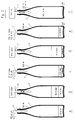
- This process step which in FIG. 2 in position a is reproduced, is in time and / or by the choice of Vacuum P3 in the vacuum channel 8 controlled so that about a 90% vacuum is obtained in the respective bottle 7, i.e. only about 10% of what was originally in the bottle Air volume remained in this.
- bottle 7 is a 1.0 l bottle with a total volume of 1030 ml, so are at the end this process step about 103 ml of air in the Bottle 7, i.e. 927 ml of air were removed.
- valve 21 After expiry of an electronic control device 40 Freely selectable evacuation time, the valve 21 is again closed. This opens at the same time or afterwards Valve 35, through which a connection between the Steam channel 37 and the space 25 is made so that steam via the return gas pipe 13 ′ protruding into the bottle 7 flows into the interior of the bottle 7, for a first rinsing this interior with saturated steam.
- About the Control electronics 40 is the opening time of the valve 35 so preselected or controlled that such an amount of steam in the bottle is inserted, which is about a quarter of the Total volume of the bottle, i.e. corresponds to about 250 ml.
- the flushing time can be varied by the control device 40 be, so that any amount of steam can be enlarged is possible with this first rinse.
- the check valve 33 is also in this method step due to the pressure difference between the Pressure P2 of the return gas collecting duct 6 and the pressure in Interior of bottle 7 closed. To do this reliably reach, the pressure P2 is greater than the pressure P4 im Steam channel 37.
- This first rinse of the bottle is in position b Fig. 2 reproduced.
- the valve 35 becomes again closed.
- the valve 21 is opened immediately thereafter and thus a connection of the interior of the bottle 7 with the vacuum channel. So there is another Evacuation of the bottle 7 via the return gas duct 13 90% vacuum, i.e. it will be according to the illustration position c of Fig. 2 from the bottle about 177 ml of steam and 73 ml of residual air removed, so that in the bottle about 73 ml of steam and 30 ml of air remain.
- valve 21 After expiry of the freely selectable via the control electronics 40 Time for the second evacuation, the valve 21 is closed. Analogous to method step 2, opening the Valves 35 in turn saturated steam from the steam channel 37 the return gas duct 13 is blown into the bottle 7, specifically in turn controlled an amount of steam that is about a quarter corresponds to the total volume of the bottle, i.e. about 250 ml.
- the input is controlled Steam amount by controlling the opening time of the valve 35. By extending the opening or rinsing time, the introduced amount of steam changed, for example, increased will.
- This second rinse also has the advantage that by evacuating the saturated steam temperature beforehand is very low, so condensation is avoided.
- Valve 35 For the initiation of this process step, which is also called End evacuation of the bottle 7 can be called that Valve 35 closed again.
- the valve 21 is again opened, which again connects the interior of the Bottle 7 with the vacuum channel 8 is made and a Evacuate the bottle 7 via the return gas pipe 13 ' about 90% vacuum takes place.
- This step is in 2 shown in position e.
- the valve 21 is closed in a time-controlled manner. Simultaneously or immediately thereafter, the valve 22 is opened, thus establishing an unthrottled connection between the return gas collection channel 6 and the interior of the bottle 7, specifically via the open valve 22, the channels 30, 28 and 29, the space 25 and the return gas channel 13. the interior of the bottle 7 is compared with the CO2 - biased gas from the return gas collecting channel on the local pressure P2.
- CO2 - Gas used, that is, the CO2 emitted during filling 6 to the return gas collecting channel - gas quantity is thus recovered for the process.
- the valve 22 is closed in a time-controlled manner by the control device 40. Then the control valve 23 is opened, thus establishing an unthrottled connection between the interior of the bottle 7 and the gas space 5, via the channels 31 and 24, the space 5, the return gas channel 13 and the opened valve 23.
- the interior of the bottle 7 is compared with the CO2 -, biased gas from the gas space 5, which also has a high concentration of CO2, and that is on the adjusted in the gas space 5 filling pressure P1, for example, an overpressure of 2.5 bar.
- the check valve 33 opens, so that a throttled connection to the return gas collecting duct 6 results via this valve and the throttle 34.
- the here over flowing during pretensioning amount of CO2 - but gas can be neglected, especially since this CO2 - gas from the return gas collecting duct 6 again for the partial tempering (step 6) is used.
- the connection between the bottle 7 and the gas space 5 is interrupted by closing the valve 23.
- the liquid valve 16 is opened.
- the ball valve 33 remains open.
- the throttle 34 provides a throttling of the displaced from the bottle 7 via the return gas passage 13 into the return gas collecting duct 6 CO2 - Gas flow, and thus for a gentle and slow Angioll Anlagen.
- the filling speed actually achieved here results from the effective cross section of the throttle 34 and from the pressure difference between the pressures P1 and P2. These parameters can be set depending on the sensitivity of the product to be filled.
- the duration of the filling phase is controlled by the control electronics 40 and is limited, for example, to a few 100 ms. Slow filling is not necessary for insensitive products.
- the valve 23 is opened so that over the return gas channel 13 and the open valve 23 an unthrottled gas path in the gas space 5 results, namely in addition to the gas path via the throttle 34, which is one Filling speed that is essentially determined by the static height difference between the level N of the product level in the ring bowl 3 and in the respective bottle 7 is determined.
- the filling speed can meet the requirements of each Contents and / or the shape of the respective bottle 7 be adjusted.
- the quick filling phase ends when the product level has reached the narrowing bottleneck, namely controlled by the probe 14 or by one at the lower end this probe provided probe contact 15.
- the rapid filling phase can also be time-controlled by the control electronics 40 are ended.
- valve 23 After the rapid filling phase, the valve 23 turns again closed, so that the same filling speed as when filling slowly. After addressing the Probe 14 or one further towards the probe tip probe contact placed at the top is after a preselectable or set correction time the liquid valve 16 closed.
- a settling phase can not ascend dissolved gas bubbles to the surface in the presence of the filling material, whereby the formation of foam in the bottle or the bottle neck is avoided.
- the valve 22 is closed and the valve 21 by the Control electronics 40 opened briefly, for one Connection of the interior of the bottle to the vacuum channel 8.
- the opening time of the Valves 21 dimensioned so that immediately before pulling the bottle 7 from the filling element 1 inside the bottle there is a slight overpressure.
- the bottle 7 will then by lowering the bottle plate 39 in the usual way subtracted from the filling element 1.
- the method described above has the advantage of extremely low CO2 - consumption as well as the advantage of an economical use of steam.
- a consumption of CO2 - gas is generated only during the final depressurization by the emitted into the vacuum channel 8 gas quantity. This amount of gas is extremely small, even if only because of the low volume, which in the final depressurization of CO2 - is taken gas.
- the total amount of CO2 - gas consumed when relieving the load, ie when filling, is 30 - 50 g per hectoliter of filling.
- the amount of steam consumed when washing bottles 7 taking into account losses caused by Condensation occurs about 113 g of bottled per hectoliter Product.
- the probe 14 preferably has at least two probe contacts 15 at different heights on so that the initiation and termination with these contacts of step 10 can be controlled.
Landscapes
- Physics & Mathematics (AREA)
- Fluid Mechanics (AREA)
- Chemical & Material Sciences (AREA)
- Chemical Kinetics & Catalysis (AREA)
- Filling Of Jars Or Cans And Processes For Cleaning And Sealing Jars (AREA)
Claims (12)
- Procédé de remplissage de bouteilles ou de récipients analogues (7) avec une charge de remplissage liquide en utilisant un système de remplissage comprenant au moins un élément de remplissage (1), un canal de liquide (10) formant une ouverture de délivrance (12) pour la charge de remplissage liquide et présentant une vanne à liquide (16), ainsi qu'au moins une voie de gaz (13), procédé dans lequel le récipient respectif (7) se trouvant en position hermétique avec l'élément de remplissage (1) est préchargé lors d'une phase de précharge par la voie de gaz avec un gaz inerte, de préférence du CO2 gazeux, gaz qui, lors d'une phase de remplissage suivante au cours de laquelle, la vanne à liquide (16) étant ouverte, la charge de remplissage liquide s'écoute à l'intérieur du récipient par l'intermédiaire de l'ouverture de délivrance (12), est refoulé au moins par moment par la voie de gaz (13) vers un canal (6) de collecte de gaz de retour, et dans lequel (procédé) la phase de précharge est précédée dans le temps par une phase de prétraitement au cours de laquelle l'intérieur du récipient respectif est rincé pour en chasser l'air et l'intérieur du récipient est exposé à une dépression (mise sous vide du récipient) et de la vapeur est introduite dans le récipient (7), caractérisé en ce que le rinçage dans la phase de prétraitement s'effectue exclusivement en employant de la vapeur, à savoir par au moins un premier rinçage et un autre rinçage suivant dans le temps, chaque rinçage s'accompagnant d'abord d'une mise sous vide de l'intérieur du récipient (7) puis d'une introduction contrôlée d'une quantité prédéterminée de vapeur dans l'intérieur du récipient (7), indépendamment de la puissance avec laquelle est exploitée le système de remplissage, et en ce que le dernier rinçage dans le temps est suivi d'une nouvelle mise sous vide de l'intérieur du récipient (7).
- Procédé selon la revendication 1, caractérisé en ce que l'introduction de vapeur s'effectue à chaque fois de manière contrôlée dans le temps.
- Procédé selon la revendication 1 ou 2, caractérisé en ce que, pour chaque mise sous vide, l'intérieur du récipient (7) est relié par un premier dispositif à vanne de commande (21) d'une manière contrôlée dans le temps à une source de pression négative, par exemple à un canal sous vide (8).
- Procédé selon l'une des revendications 1 à 3, caractérisé en ce que, pour l'introduction de la quantité prédéterminée de vapeur lors de chaque rinçage, l'intérieur du récipient (7) est relié par un deuxième dispositif à vanne de commande (35) d'une manière contrôlée dans le temps à une source de vapeur, de préférence un canal de vapeur (37).
- Procédé selon l'une des revendications 1 à 4, caractérisé en ce que, dans la phase de prétraitement, il se produit une première mise sous vide avec ensuite une première introduction de vapeur, puis une deuxième mise sous vide avec ensuite une deuxième introduction de vapeur et une troisième mise sous vide, à laquelle fait suite la précharge du récipient (7) avec un gaz inerte.
- Procédé selon l'une des revendications 1 à 5, caractérisé en ce que la pression négative de la source de pression négative (8) ainsi que la durée de la mise sous vide respective du récipient sont choisies en sorte qu'il s'instaure dans le récipient, au terme de la mise sous vide, à chaque fois une dépression d'environ 0,5 à 0,95 bar.
- Procédé selon l'une des revendications 1 à 6, caractérisé en ce que la pression négative de la source de pression négative (8) ainsi que la durée de la mise sous vide respective du récipient sont choisies en sorte que le récipient (7) soit mis sous vide environ à 90% de son volume total.
- Procédé selon l'une des revendications 1 à 7, caractérisé par l'utilisation d'une vapeur saturée à une température comprise entre environ 111 et 155°C et à une surpression d'environ 0,5 à 4,5 bar, de préférence à une température entre 120 et 130°C et une surpression d'environ 1,0 à 2,5 bar.
- Procédé selon l'une des revendications 1 à 8, caractérisé en ce que l'alimentation de l'intérieur du récipient (7) s'effectue avec une pression de vapeur (P4) qui est inférieure à une pression instaurée dans le canal (6) de collecte de gaz de retour.
- Procédé selon l'une des revendications 1 à 9, caractérisé en ce que, dans la voie de gaz par laquelle le gaz inerte est refoulé au moins par moments dans le canal (6) de collecte de gaz de retour pendant la phase de remplissage, il est prévu une soupape antiretour (33), qui ne s'ouvre que lorsque la pression dans le récipient est supérieure à la pression dans le canal (6) de collecte de gaz de retour.
- Procédé selon l'une des revendications 1 à 10, caractérisé en ce que la pression négative de la source de pression négative (8) ainsi que la durée de la mise sous vide respective du récipient sont choisies en sorte qu'à l'intérieur du récipient (7), il s'instaure après la mise sous vide une dépression pour laquelle la température d'évaporation de l'eau ou la température de vapeur saturante vaut environ entre 40 et 60°C, de préférence 45°C.
- Procédé selon l'une des revendications 1 à 11, caractérisé en ce que la précharge du récipient (7) s'effectue partiellement sur le canal (6) de collecte de gaz de retour.
Applications Claiming Priority (2)
| Application Number | Priority Date | Filing Date | Title |
|---|---|---|---|
| DE4434174 | 1994-09-24 | ||
| DE4434174A DE4434174A1 (de) | 1994-09-24 | 1994-09-24 | Verfahren zum Abfüllen eines flüssigen Füllgutes in Flaschen oder dergleichen Behälter |
Publications (3)
| Publication Number | Publication Date |
|---|---|
| EP0705788A2 EP0705788A2 (fr) | 1996-04-10 |
| EP0705788A3 EP0705788A3 (fr) | 1996-06-12 |
| EP0705788B1 true EP0705788B1 (fr) | 1998-08-19 |
Family
ID=6529110
Family Applications (1)
| Application Number | Title | Priority Date | Filing Date |
|---|---|---|---|
| EP95114683A Expired - Lifetime EP0705788B1 (fr) | 1994-09-24 | 1995-09-19 | Procédé pour remplir des bouteilles ou des récipients similaires avec un produit liquide |
Country Status (2)
| Country | Link |
|---|---|
| EP (1) | EP0705788B1 (fr) |
| DE (2) | DE4434174A1 (fr) |
Families Citing this family (8)
| Publication number | Priority date | Publication date | Assignee | Title |
|---|---|---|---|---|
| DE19818762A1 (de) * | 1998-04-27 | 1999-10-28 | Khs Masch & Anlagenbau Ag | Füllsystem sowie Füllelement |
| DE20110362U1 (de) * | 2001-06-22 | 2001-08-30 | KHS Maschinen- und Anlagenbau AG, 44143 Dortmund | Füllrohrloses Füllelement für eine Füllmaschine zum sauerstoffarmen Abfüllen eines Getränks |
| DE102004017205A1 (de) * | 2004-04-10 | 2005-10-27 | Khs Maschinen- Und Anlagenbau Ag | Füllmaschine umlaufender Bauart |
| DE102013103192A1 (de) * | 2013-03-28 | 2014-10-02 | Khs Gmbh | Verfahren sowie Füllsystem zum Füllen von Behältern |
| DE102015111374A1 (de) | 2015-07-14 | 2017-01-19 | Krones Ag | Vorrichtung und Verfahren zum Einleiten eines Gases in einen mit einem Füllprodukt zu befüllenden Behälter |
| DE102016108502A1 (de) * | 2016-05-09 | 2017-11-09 | Khs Gmbh | Verfahren zum Füllen von Behältern |
| CN106365098A (zh) * | 2016-10-21 | 2017-02-01 | 张家港市万金机械有限公司 | 一种灌油阀 |
| DE102022102522A1 (de) | 2022-02-03 | 2023-08-03 | Khs Gmbh | Füllgutkessel sowie Abfüllmaschine |
Family Cites Families (5)
| Publication number | Priority date | Publication date | Assignee | Title |
|---|---|---|---|---|
| DE3731757A1 (de) * | 1987-09-22 | 1989-03-30 | Orthmann & Herbst | Fuellorgan fuer getraenkefuelleinrichtungen mit vorevakuierung |
| DE4126136A1 (de) * | 1991-08-07 | 1993-02-11 | Seitz Enzinger Noll Masch | Fuellelement |
| GB2260315B (en) * | 1991-10-08 | 1995-08-02 | Guinness Brewing Worldwide | A method of and apparatus for packaging a beverage in a container |
| DE4207829A1 (de) * | 1992-03-12 | 1993-09-16 | Magdeburg Getraenkemasch | Verfahren und vorrichtung zum sterilen abfuellen von getraenken |
| EP0614850A1 (fr) * | 1993-03-10 | 1994-09-14 | KHS Maschinen- und Anlagenbau Aktiengesellschaft | Tête de remplissage pour embouteilleuse pour remplir de bouteilles ou des récipients similaires avec un liquide |
-
1994
- 1994-09-24 DE DE4434174A patent/DE4434174A1/de not_active Withdrawn
-
1995
- 1995-09-19 DE DE59503251T patent/DE59503251D1/de not_active Expired - Lifetime
- 1995-09-19 EP EP95114683A patent/EP0705788B1/fr not_active Expired - Lifetime
Also Published As
| Publication number | Publication date |
|---|---|
| EP0705788A3 (fr) | 1996-06-12 |
| EP0705788A2 (fr) | 1996-04-10 |
| DE59503251D1 (de) | 1998-09-24 |
| DE4434174A1 (de) | 1996-03-28 |
Similar Documents
| Publication | Publication Date | Title |
|---|---|---|
| EP0697369B1 (fr) | Procédé pour remplir des bouteilles ou analogues au moyen d'un liquide | |
| EP0365867B1 (fr) | Procédé et dispositif pour remplir des boîtes de boisson | |
| EP0582190B1 (fr) | Dispositif de remplissage de bouteilles ou de récipients analogues | |
| EP0331137B1 (fr) | Procédé et dispositif de remplissage, sous contre-pression, de récipients avec des liquides carbonatés, en particulier des boissons | |
| WO2005056464A1 (fr) | Element de remplissage pour machine de remplissage et machine de remplissage equipee d'elements de remplissage de ce type | |
| EP0953541A1 (fr) | Dispositif et élément de remplissage | |
| EP1216952B1 (fr) | Machine de remplissage | |
| DE102013102611A1 (de) | Verfahren zum Spülen von Behältern | |
| DE19836500A1 (de) | Füllsystem | |
| EP1544156B1 (fr) | Tête de remplissage avec canal separé d'évacuation des gaz | |
| EP0953542A2 (fr) | Vanne de remplissage pour une machine de remplissage | |
| EP0615948A2 (fr) | Soupape de remplissage pour une remplisseuse | |
| WO2001012507A1 (fr) | Dispositif de conservation d'une bouteille pour boissons felee | |
| DE102013104938A1 (de) | Füllsystem sowie Füllmaschine zum Füllen von Behältern | |
| EP0588356B1 (fr) | Dispositif de remplissage de bouteilles ou de récipients similaires | |
| DE4402980C1 (de) | Füllsystem zum Abfüllen eines flüssigen Füllgutes in Flaschen, Dosen oder dgl. Behälter | |
| EP0705788A2 (fr) | Procédé pour remplir des bouteilles ou des récipients similaires avec un produit liquide | |
| EP1270499A1 (fr) | Elément de remplissage sans tube de remplissage pour des machines de remplissage pauvre en oxygène de boissons | |
| DE2454888A1 (de) | Flaschenfuellmaschine | |
| DE4342142C2 (de) | Vorrichtung zum Füllen von Flaschen oder dergl. Behälter mit einem flüssigen Füllgut | |
| EP0308721B1 (fr) | Organe de remplissage pour installation d'embouteillage de boissons, avec dispositif de nettoyage préalable | |
| EP0554690A1 (fr) | Procédé de remplissage des bouteilles ou de récipients similaires avec un produit liquide et dispositif pour la mise en oeuvre du procédé | |
| DE102020110899A1 (de) | Verfahren zum Befüllen von Behältern | |
| DE3819349C2 (de) | Verfahren und Vorrichtung zum Abfüllen von gashaltigen Getränken in Flaschen | |
| DE3725609A1 (de) | Fuellelement fuer behaelterfuellmaschine |
Legal Events
| Date | Code | Title | Description |
|---|---|---|---|
| PUAI | Public reference made under article 153(3) epc to a published international application that has entered the european phase |
Free format text: ORIGINAL CODE: 0009012 |
|
| AK | Designated contracting states |
Kind code of ref document: A2 Designated state(s): BE DE FR IT NL |
|
| PUAL | Search report despatched |
Free format text: ORIGINAL CODE: 0009013 |
|
| AK | Designated contracting states |
Kind code of ref document: A3 Designated state(s): BE DE FR IT NL |
|
| 17P | Request for examination filed |
Effective date: 19960716 |
|
| GRAG | Despatch of communication of intention to grant |
Free format text: ORIGINAL CODE: EPIDOS AGRA |
|
| GRAG | Despatch of communication of intention to grant |
Free format text: ORIGINAL CODE: EPIDOS AGRA |
|
| GRAH | Despatch of communication of intention to grant a patent |
Free format text: ORIGINAL CODE: EPIDOS IGRA |
|
| GRAH | Despatch of communication of intention to grant a patent |
Free format text: ORIGINAL CODE: EPIDOS IGRA |
|
| 17Q | First examination report despatched |
Effective date: 19980206 |
|
| ITF | It: translation for a ep patent filed | ||
| GRAA | (expected) grant |
Free format text: ORIGINAL CODE: 0009210 |
|
| AK | Designated contracting states |
Kind code of ref document: B1 Designated state(s): BE DE FR IT NL |
|
| REF | Corresponds to: |
Ref document number: 59503251 Country of ref document: DE Date of ref document: 19980924 |
|
| ET | Fr: translation filed | ||
| PLBE | No opposition filed within time limit |
Free format text: ORIGINAL CODE: 0009261 |
|
| STAA | Information on the status of an ep patent application or granted ep patent |
Free format text: STATUS: NO OPPOSITION FILED WITHIN TIME LIMIT |
|
| 26N | No opposition filed | ||
| REG | Reference to a national code |
Ref country code: NL Ref legal event code: TD Effective date: 20111114 |
|
| REG | Reference to a national code |
Ref country code: FR Ref legal event code: CD Owner name: KHS GMBH Effective date: 20111122 Ref country code: FR Ref legal event code: CD Owner name: KHS GMBH Effective date: 20111121 |
|
| BECN | Be: change of holder's name |
Owner name: KHS G.M.B.H. Effective date: 20120314 |
|
| PGFP | Annual fee paid to national office [announced via postgrant information from national office to epo] |
Ref country code: DE Payment date: 20140922 Year of fee payment: 20 |
|
| PGFP | Annual fee paid to national office [announced via postgrant information from national office to epo] |
Ref country code: FR Payment date: 20140919 Year of fee payment: 20 |
|
| PGFP | Annual fee paid to national office [announced via postgrant information from national office to epo] |
Ref country code: NL Payment date: 20140918 Year of fee payment: 20 |
|
| PGFP | Annual fee paid to national office [announced via postgrant information from national office to epo] |
Ref country code: IT Payment date: 20140929 Year of fee payment: 20 |
|
| PGFP | Annual fee paid to national office [announced via postgrant information from national office to epo] |
Ref country code: BE Payment date: 20140919 Year of fee payment: 20 |
|
| REG | Reference to a national code |
Ref country code: DE Ref legal event code: R071 Ref document number: 59503251 Country of ref document: DE |
|
| REG | Reference to a national code |
Ref country code: NL Ref legal event code: MK Effective date: 20150918 |