EP0706111A2 - Appareil et méthode pour interface d'utilisateur - Google Patents
Appareil et méthode pour interface d'utilisateur Download PDFInfo
- Publication number
- EP0706111A2 EP0706111A2 EP95113658A EP95113658A EP0706111A2 EP 0706111 A2 EP0706111 A2 EP 0706111A2 EP 95113658 A EP95113658 A EP 95113658A EP 95113658 A EP95113658 A EP 95113658A EP 0706111 A2 EP0706111 A2 EP 0706111A2
- Authority
- EP
- European Patent Office
- Prior art keywords
- input parameter
- value
- transfer function
- cursor
- signal
- Prior art date
- Legal status (The legal status is an assumption and is not a legal conclusion. Google has not performed a legal analysis and makes no representation as to the accuracy of the status listed.)
- Granted
Links
Images


Classifications
-
- G—PHYSICS
- G06—COMPUTING OR CALCULATING; COUNTING
- G06F—ELECTRIC DIGITAL DATA PROCESSING
- G06F3/00—Input arrangements for transferring data to be processed into a form capable of being handled by the computer; Output arrangements for transferring data from processing unit to output unit, e.g. interface arrangements
- G06F3/01—Input arrangements or combined input and output arrangements for interaction between user and computer
- G06F3/03—Arrangements for converting the position or the displacement of a member into a coded form
- G06F3/033—Pointing devices displaced or positioned by the user, e.g. mice, trackballs, pens or joysticks; Accessories therefor
- G06F3/038—Control and interface arrangements therefor, e.g. drivers or device-embedded control circuitry
- G06F3/0383—Signal control means within the pointing device
Definitions
- the invention generally relates to the field of graphical user interfaces for computers and processing systems. More particularly, the invention relates to an apparatus and method for translating user input movements into movements of a symbol, such as a cursor, on the graphical user interface.
- GUIs Graphical User Interfaces
- GUI various images, including icons, windows containing application programs, and other objects or items appear on a display screen.
- the icons and windows are graphical representations of application programs or utility functions.
- the user operates the system by moving images on the screen, and by providing input signals to the system, which the system interprets as commands to operate the application programs or utility functions.
- the image which the user moves about the screen is a cursor, although the user can also move other types of images around.
- the cursor must be precisely positioned on the desired icon, application program button, or another object or item for the input signals to be interpreted as desired.
- the user employs a user interface apparatus which includes a transducer for translating the user's activity, such as hand movements, fingertip pressure, etc., into an input parameter.
- a transducer for translating the user's activity, such as hand movements, fingertip pressure, etc.
- Various types of devices include such transducers.
- a popular device for enabling the user to perform cursor movements and to enter commands is called a mouse.
- a mouse is a mechanically simple device for producing a signal, responsive to physical displacement of the mouse by the user, which directs the system to move the cursor about the display screen.
- a mouse also includes one or more push buttons, which the user pushes in order to enter commands to the system. Responsive to a given movement of the mouse in a given direction, such as over a mouse pad or work surface, the cursor makes a movement in a corresponding direction on the display screen.
- the input parameter can be a positional movement, i.e. a displacement or translation, or can also include factors relating to mouse velocity, as well as displacement.
- the mapping is from a mouse position (or velocity) to a cursor position.
- a joystick may also be used for cursor movement.
- a typical joystick such as that used in video games, is spring-biased in two dimensions to a middle position, corresponding with no cursor movement. Movement of the joystick responsive to user manipulation causes cursor movement.
- displacement of the joystick or a magnitude of force applied against it, serve as the input parameter.
- the input parameter of a joystick is position, i.e., displacement from a resting position, and the mapping is from joystick position to cursor velocity (or, in some systems, cursor position).
- An isometric joystick is implemented as the TrackPoint II pointing device, currently available in the ThinkPad line of laptop computers by IBM Corporation. (TrackPoint II, ThinkPad, and IBM are registered trademarks of International Business Machines Corporation.)
- ThinkPad laptop computers include TrackPoint II pointing devices, conveniently built into the middle of the keyboard, between the G and H keys.
- ThinkPad units also include keyboard buttons, analogous to mouse buttons, for entering system commands.
- a user operates a TrackPoint II device by pushing laterally against the top of the device with his/her fingertip.
- the device does not actually displace, as in the case with a joystick.
- the input parameter is the force applied by the user, and the force is mapped to cursor movement.
- the force against the device is sensed, and the cursor movement is made at a rate determined by the transfer function, over the length of time the pressure is applied.
- the speed of cursor movement may be proportional to the magnitude of the force applied, or have some other predetermined relationship, as defined by the device's transfer function.
- the TrackPoint II device is implemented as having a sigmoid transfer function, including a "dead zone" in which very small forces are ignored, and a series of regions in the input parameter domain, where, in each region, the cursor movement is a piecewise linear function of the input parameter. The piecewise linear segments approximate the sigmoid shape.
- Mice, joysticks, and TrackPoint II devices have in common the fact that cursor movement is related to an input parameter whose value is determined by user manipulation.
- the user In order to use one of these user interface devices effectively and comfortably, the user must develop a hand-eye coordination to efficiently move the cursor where he or she wants it to go. Whether this coordination will be comfortable for the user depends greatly on both the intrinsic feel of the interface device, i.e., the nature of the user manipulation which produces the input parameter, and the particular transfer function which translates, or maps, the input parameter to actual cursor movement.
- one of the fundamental problems in the ergonomics of GUIs is the problem of just how to map the input parameter into cursor movement.
- a good solution to this problem would facilitate such hand-eye coordination, i.e., provide a "good user feel".
- the terms "transfer function,” “mapping,” and “dynamic response” are used to denote the means by which the input parameter is translated into cursor movement.
- a poor solution to the problem makes use of the interface difficult for the user. If hand-eye coordination is difficult for the user, many annoying manifestations, such as minor movements of the cursor to locate the cursor precisely on the desired location, result.
- cursor movement or speed is proportional or otherwise related, at any given point in time, to the magnitude of the input parameter at that point in time.
- Inertia is the feeling that a cursor just beginning motion is sluggish, or that a moving cursor will not stop responsively enough, so that it will tend to overshoot the desired destination on the display screen. Therefore, other types of transfer functions have been considered in order to improve user feel or hand-eye coordination by dealing with transients.
- Levine U.S. Patent No. 4,386,346, "Cursor Controller”.
- a controller intended to decrease the tendency for cursor movement to overshoot the intended target.
- Levine proposes to reduce the tendency to overshoot by compensating for the user's reaction time. This goal is accomplished by providing a control circuit which generates a correction signal having a value related to the speed of cursor movement and to the user's reaction time.
- the correction signal is of the right magnitude to compensate for the amount of overshoot resulting from the user's reaction time at the speed at which the cursor was moving.
- the user's reaction time is established, initially, by using a table of correction values based on an average user reaction time. Later, the numbers in the table are changed to more accurately reflect the reaction time of the individual user (column 4, lines 30-33).
- an assumption is made that the user will overshoot the desired cursor destination by a distance related to the reaction time.
- An overshoot voltage signal is calculated based on the reaction time.
- a correction voltage signal equal to the overshoot voltage signal, is then calculated and applied to the cursor to move it back from the position reached by overshooting to the intended destination.
- the operation of the Levine transfer function depends both on the instantaneous state of the user's input (i.e., the dropoff of the input toward zero), and on the user's input which has occurred in the immediate past (i.e., the input during the interval where the user is seeking to move the cursor toward the desired destination).
- Felsenstein takes a more sophisticated approach to dealing with transients. Felsenstein begins by observing that the transfer function, or “dynamic response,” should be “different for slowing actions than it is for speeding actions” (column 2, lines 31-32). It acknowledges the use of a “quickening" circuit for smoothing operation at a point of transition (column 2, lines 15-18), and provides a circuit, whose behavior is described starting at column 5, line 57, responsive to displacements of a joystick.
- FIG. 1 of the present patent application The Felsenstein circuit is reproduced in FIG. 1 of the present patent application, as a showing of prior art.
- the reference numbers which appear in this drawing, as it appears in the Felsenstein patent, have been left intact.
- the full discussion of the illustrated components, referenced by number, has been omitted.
- the reader of this patent application is directed to the Felsenstein patent itself for that discussion.
- the comments on FIG. 1 which follow will be limited to certain individual points relating to the illustrated circuit.
- the values are those associated with various components of the circuit of FIG. 1. That is, C is the value of capacitors 40 and 42, the voltages are those whose subscripts match the circuit junctions likewise numbered, and the resistance values are the resistances of analog transmission gates likewise numbered.
- Felsenstein's transfer function acts as a low pass filter, and behaves even more sluggishly than other conventional systems. Felsenstein asserts, at column 6, lines 6-9, that this behavior is "more kinaesthetically pleasing to an operator" than a conventional transfer function.
- Felsenstein differentiates the joystick signal, using a differentiator 22 in FIG. 1.
- this differentiated signal is not used directly as part of the input parameter to be applied to the transfer function to obtain the cursor movement signal. Rather, the differentiated signal is applied to a discriminator circuit 26, whose comparators 28 and 30 drive inputs of a latch 32, based on the polarity of the differentiated signal. That is, the high-true and low-true outputs (34 and 36, respectively) of the latch 32 respectively indicate whether the signal is increasing or decreasing.
- line 58, through column 5, line 4 there is a description of the circuitry used for switching the network of analog transmission gates (ATGs) and the capacitors 40 and 42. The switching is used to select between two different levels of sluggishness.
- ATGs analog transmission gates
- the invention provides an apparatus, for use in a graphical user interface of a processing system, for directing the positioning and movement of a symbol displayed on a display screen of the processing system, the apparatus comprising a transducer for translating an input activity of a user into an input parameter; and a transfer function unit, coupled to receive the input parameter, for producing a symbol movement signal whose value, responsive to the input parameter, represents an amplification of changes of value of the input parameter, the amplification having the same sign as the changes of value of the input parameter, the amplification including non-linear scaling; whereby the amplification of changes of value of the input parameter is reduced for low magnitude of the input parameter, representative of user activity to make small cursor movements; and whereby movement of the symbol on the screen is controlled based on the symbol movement signal.
- the input parameter changes from zero to a finite value. That finite value, by itself, would result in a given cursor movement using a conventional transfer function.
- the amplification of the change in input parameter value in accordance with the invention causes the symbol to move on the screen with greater responsiveness than is the case conventionally. Accordingly, the invention achieves the advantageous reduction in perceived symbol inertia, and therefore provides better user feel.
- symbol will be used to mean any image, cursor, icon, window, or other object or item which is displayed on a GUI screen.
- the input parameter is treated as a function of time, reflecting the time-varying nature of the user's actions.
- This time-varying input parameter can be either a continuous parameter, or a sequence of discrete time values, such as a sequence of values produced by sampling a continuous parameter.
- the invention may more easily be understood in terms of its square wave response. Responsive to a transition of the input parameter from the first value to the second value, the transfer function unit produces a cursor movement signal whose value changes from an initial value and approaches a steady-state value after having a value which, during a transient period, differs from the initial value in excess of a difference between the initial value and the steady state value. Movement of the cursor on the screen is then controlled, based on the cursor movement signal.
- the transfer function unit preferably includes an additive high-pass filter.
- the APPENDIX is a pseudocode listing of a preferred software implementation of the invention.
- one important manifestation solved by the embodiment occurs during transients, i.e., when the user starts or stops cursor motion.
- the user When a user begins moving the cursor, the user clearly wants to move the cursor somewhere.
- a finite, perceivable time is required to apply the appropriate force in order to get the cursor moving at the velocity desired. If that time is large enough, as is the case with conventional user interfaces, then the user can become frustrated by the sluggishness of the cursor.
- the user releases the force on the user interface device when the cursor reaches the desired destination then, as the force drops to zero during a finite time, the cursor overshoots the destination.
- transient period will not necessarily be limited to the time during which the input parameter is in a transition, but may additionally include some subsequent time interval during which the negative inertia output continues changing value.
- a transfer function is provided as shown in the graph of FIG. 2.
- An input parameter curve 202 is shown in the form of a "square wave,” moving from zero to a finite, positive value at a first time, and returning to zero at a second, later, time (solid line).
- an output curve 204 shown as a dotted line, illustrates a transfer function in accordance with the invention.
- FIG. 2 in essence shows the "square wave response" of the transfer function of the invention, which is commonly recognized as a useful way of illustrating and understanding transfer functions.
- the transfer function is additive, in that it is a sum of a first signal and a second signal related to the rate of change of the first signal. Specifically, if the first signal is taken as a square wave, then the second signal is an upward going pulse coincident in time with the rising edge of the square wave, and a downward going pulse coincident in time with the falling edge of the square wave. The sum of these two signals looks like the curve 204 of FIG. 2.
- a preferred implementation of the invention involves using a high-pass filter to produce the second such signal, and summing the high-pass filtered signal with the original signal.
- the output exceeds a steady state magnitude for a transient period following an upward transient, and the output falls below the steady state magnitude for a transient period following a downward transient. This is illustrated in the form of regions 206 and 208, respectively, which lie between the two curves during the transient periods.
- the curve 204 may be described as changing in value from an initial value and approaching a steady-state value after having a value which, during a transient period, differs from the initial value in excess of a difference between the initial value and the steady state value.
- An additive high-pass filter is a convenient way of implementing the invention, since the excess of the output signal 204, beyond that of the input signal 202, is the result of the addition of the high-pass filtered signal.
- other techniques may be used to accomplish similar results.
- a user interface having a transfer function according to the invention overcomes the inertia problem described in the Background.
- a user interface according to the invention may be described as having "negative inertia.”
- pulse height, decay time, and other pulse parameters could be designed to depend on the sign of the transient, the magnitude of the transient, the time since the last significant transient, the magnitude and sign of the applied force or other input parameter, or any number of other factors which could be used to produce a better user feel.
- FIG. 3 is a graph which shows cursor motion in accordance with the invention.
- An input parameter is shown as a user input transducer force curve 302.
- the curve 302 has a quiescent or idle state corresponding with zero applied force and zero desired cursor motion, and an input force scale, representing arbitrary units of input force for illustrative purposes.
- the input parameter increases from zero to a finite, constant value. Later, the user releases the transducer, and over another finite time, the input parameter returns to zero.
- FIG. 3 Also shown in FIG. 3 are two curves representing cursor motion, responsive to the input parameter.
- a dotted line 304 represents the cursor motion using a conventional user interface
- a solid line 306 represents the cursor motion using a user interface according to the invention. Again, arbitrary units of cursor motion, which represent cursor displacement, are given.
- the time scale is common for both the input force curve 302 and the output cursor motion curves 304 and 306, and is given in terms of arbitrary units.
- the curve according to the invention moves above the conventional curve. This is the result of the negative inertia effect of the transfer function according to the invention.
- the square-wave-type curve 202 looks essentially the same as a curve representing the velocity of the movement of a conventional cursor, while the curve 204 looks like a velocity curve according to the invention. Accordingly, the greater velocity of the cursor according to the invention is represented in FIG. 3 in the time period 308, during which the cursor according to the invention moves at a greater velocity, and therefore the cursor, according to the invention, moves ahead of its conventional pace.
- the cursor in motion according to the invention, reaches the desired destination. Accordingly, the user begins to release the force on the transducer, so the curve 302 drops back to zero.
- the region 208 can be interpreted to represent a difference between the stopping of the cursor conventionally (the curve 202) and according to the invention (the curve 204).
- the region 208 of FIG. 2 represents the degree to which, during the second transient time, the (negative) difference between the curve 204 after and before the transition exceeds the steady state difference, represented in FIG. 2 as the difference between the signal strength values 1 and 0.
- the negative inertia characteristic of the transfer function causes the cursor motion to react to the second transient by stopping faster than it would in a user interface using a conventional transfer function, such as the conventional instantaneous linear transfer function.
- the cursor motion also reacts to the second transient by backing up, i.e., by decreasing in value, during the second transient period 312.
- the less reactive, conventional curve merely comes to a stop, i.e., reaches a final cursor position represented by the flat portion of the curve 304 beyond the second transient period 312.
- the user begins to react by releasing the input force right about at the time at which the cursor reaches the final destination (that is, at the time when the curve 306 is about at the same height in the graph of FIG. 3 as the steady state value of both the curves 304 and 306 following the second transient). This may or may not be the case, depending on the user's reaction time, and on the user's ability to anticipate reaching the cursor's final destination, and reacting accordingly.
- an analog circuit for use with a user interface in accordance with the invention, is provided.
- an input signal "z" is received from a suitable transducer as discussed above. For instance, if a TrackPoint II type pointing device is used, the input signal z is a signal related to the force being applied to the TrackPoint device at that point in time.
- the input signal z is provided to an RC circuit, including a capacitor 404 and a resistor 406, coupled between the input to the circuit, at which is provided the input parameter, and the input of an amplifier 408.
- an RC circuit including a capacitor 404 and a resistor 406, coupled between the input to the circuit, at which is provided the input parameter, and the input of an amplifier 408.
- one possible configuration for practicing the invention is to have the capacitor 404 coupled in series between the circuit input and the input of the amplifier 408, and the resistor 406 between the input of the amplifier 408 and ground.
- Persons skilled in the art of analog circuitry will know of other circuits which have comparable characteristics, and therefore can be used as memory circuitry in place of the illustrated components.
- the RC circuit produces a signal having a differentiator, or high-pass filter, characteristic at the junction of the capacitor 404 and the resistor 406. This signal is amplified by an amplifier 408, to produce a signal designated "ACC.” This designation represents the high-pass filtered character of the signal ACC, that is, the fact that changes of value of the input signal z have been amplified, or accelerated, to produce the signal ACC.
- the additive signal z+ACC is added to the original input signal z by an adder 410, thereby producing an additive signal z+ACC.
- the additive signal z+ACC includes a differentiated, or high-pass filtered, signal ACC, added to the original signal z.
- the graph of FIG. 2 shows an example of the additive signal z+ACC.
- the additive signal z+ACC is then provided to a "transfer function" unit 412, which subjects the signal to a conventional "transfer function.”
- a user input device maps user input activity to cursor movement in accordance with a particular formula
- One such formula was the sigmoid, used in IBM's TrackPoint II device, as previously discussed.
- the present invention may be thought of as an "overlay" of that formula, since the present invention is intended to enhance the user feel, as distinct from the basic functionality of the user interface, as defined by the formula
- both the negative inertia aspect of the invention and the basic formula for a conventional device, such as that for the TrackPoint II device will be included.
- transfer function Since there is a potential for confusion in the usage of the term transfer function, the following convention regarding nomenclature will be used: Where the usage is intended to refer to the conventional formula alone, the term "transfer function" will be expressed in quotation marks. On the other hand, the term transfer function, without quotation marks, will be used to refer to the complete function, including both the "transfer function” and further functionality which implements the negative inertia aspect of the invention.
- transfer function will be recited as a first transfer function, and a signal having been subjected to the transfer function will be recited as a transfer function output.
- the preferred implementation of the invention employs a "transfer function" having a sigmoid shape, as discussed in the Background, and as implemented in IBM's TrackPoint II pointing device. A more detailed description of this implementation will be given below, in conjunction with the APPENDIX.
- the unit 412 subjects the additive signal z+ACC to the above-described "transfer function.”
- the result, f(z+ACC) is a cursor movement signal which shows both the effect of the basic "transfer function” and the amplification of the rate of change thereof.
- an additional consideration is factored in. In the course of development, it was found that this resultant signal had a disadvantageous instability, which manifested itself as excessive reactions to small adjustments of the cursor position. Therefore, further in accordance with the invention, a scaling is performed, so that the effect of the amplification of the rate of change is reduced where the input magnitude of the rate of change is low.
- the scaling is performed as follows:
- the additive signal z+ACC and the input signal z are both provided to a divider 414, as the divisor and the dividend, respectively.
- the divider 414 produces a quotient, as shown in FIG. 4. This quotient serves as a scaling factor for the output of the transfer function unit 412.
- the scaling is performed by a multiplier 416, which takes as inputs the scaling factor from the divider 414 and the output of the transfer function unit 412, and produces a product, which is provided at an output 418.
- FIG. 3 shows an example of this output signal.
- the APPENDIX provides a software implementation presently planned for inclusion in a soon-to-be-announced product offering.
- the software implementation as shown has three sections. First definitions of variables, used below in the Procedure, are provided. Among the variables defined are x and y, the x-axis and y-axis forces applied by the user to a TrackPoint II type pointing device. These variables x and y are the user inputs to the Negative Inertia Procedure. In the preferred embodiment, the x and y inputs are discrete time samples, taken at a sampling rate of 100 samples per second.
- X and Y are x-axis and y-axis cursor velocities, and are thus the cursor movement outputs of the Procedure.
- the outputs are expressed in terms of "mickeys per second."
- a mickey is a whimsically named unit of mouse movement distance, which is familiar to persons skilled in the art of GUI systems. The particular nature of a mickey is dependent on the particular type of user interface apparatus employed in a given system.
- a mickey is defined in conjunction with the X and Y variables as the distance along the X or Y axis corresponding with one integer bit of the value of the X or Y variable.
- the X and Y axes are expressed in terms of axes of the mouse itself, as distinct from the axes of the screen, or even axes of the surface over which the user moves the mouse.
- a mouse movement value expressed in mickeys, is converted into a measure of symbol movement on the screen. The conversion is done according to whatever algorithm or transfer function (generally not linear) is used by the driver and other system application software.
- the APPENDIX provides a "transfer function," f(), given as a list of subdomains of values for an input value n and formulas for computing the output value of the transfer function based on the input value within each subdomain.
- the subdomains run in value through an overall domain of values 0 through 255. This particular domain was used because the implementation given in the APPENDIX was made on an 8-bit system. Any other suitable domain could also be used.
- the output is a constant.
- the output is a function of n.
- transfer function has been used in IBM's TrackPoint II pointing device, discussed above, as implemented here. In accordance with the invention, however, additional processing of the signal to provide the advantageous negative inertia aspect of the present invention is implemented in addition to the original "transfer function.” As given in the APPENDIX, the term “transfer function” has been used to refer to the sequence of values tabulated, and implemented in IBM's existing TrackPoint II device.
- the input values, x and y are x and y components of the input parameter, such as joystick force or mouse movement.
- a magnitude z is calculated from the x and y components. Note that, while z is defined, in the Definitions, as the familiar square root of the sum of the squares of x and y, step [1a] computes z in terms of a numerical approximation thereof. In the particular implementation given in the APPENDIX, program memory space was short, so an approximation taking up less coding space was used. However, in implementations where there are no significant limitations on memory space, a suitable programming technique for calculating z in terms of a closer numerical approximation of the square-root-of-sum-of-squares formula given in the definition may advantageously be used.
- step [1b] z is reduced to a maximum value of 255, assuming that it had exceeded 255. This maximum also follows from the 8-bit implementation of the embodiment shown in the APPENDIX, and may be omitted (or suitably modified) for other implementations having different environmental limitations.
- step [2] a test is made for the condition in the first line of the transfer function, where, for n in the range 0-3, the output is 0. If n is greater than 3, the procedure continues. This test provides a small "dead band” area, in which small motions of the cursor due to noise in the measurement of the force on the transducer are disregarded.
- step [3] a discrete additive high pass filtering in accordance with the invention is made, in which a difference between z and a past value z 0 is scaled by an inertia gain factor I, and added to z to produce an inertia corrected magnitude z i .
- One of the parameters which can be set, in accordance with the invention is a time delay between the current value z and the past value z 0 .
- the delay may be expressed either in terms of a time interval, in terms of a number of values in the sequence.
- z 0 is the value from 10 milliseconds prior to the current value z.
- step [3] employs an expression including the present value and a past value, or possibly a plurality of past values, of the input parameter, or of components of the input parameter.
- step [4] Since the magnitude is unsigned, the absolute value of z i is taken in step [4]. If z i were negative, the x and y values are inverted for the calculations to be made in steps [6a] through [6c] and [7a] through [7c]. Then in step [5], the inertia corrected magnitude z i is input to the existing TrackPoint II device's "transfer function.”
- the output Z of the transfer function is scaled by the ratio of x and y, respectively, to the inertia corrected magnitude z i2 .
- Scaling could alternatively be done using the magnitude z, rather than the inertia corrected magnitude z i2 .
- the non-linear gain in the negative inertia effect which results from the use of z i2 , is preferred. This is because it is considered that good user feel results if the magnitude of the negative inertia effect, realized in accordance with the invention, is related to the magnitude of the input parameter.
- the x and y values are components of the original magnitude z.
- step [3] Since the formula for calculating the denominator, z i2 , of the ratio, Z/z i2 , is the expression given in step [3], it will be seen that, for small magnitudes of the input parameter, the ratio is also small, because the denominator value is primarily the (z-z 0 )*I term. On the other hand, for large input parameter values, the z term becomes the primary part of the denominator, and the ratio approaches the ratio of the component, x or y, to the magnitude z. Therefore, the expressions given in steps [6a] through [6c] and [7a] through [7c] are believed to produce a preferred user feel.
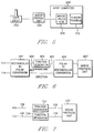
- FIG. 5 there is shown a block diagram of a system in which the invention is implemented in program code, as given in the APPENDIX.
- a user input device 502 including a transducer for producing an input parameter, is shown as an isometric joystick.
- the device 502 produces an input parameter, as described above.
- the input parameter is then provided to a protocol unit, here shown as a mouse protocol unit 504.
- a mouse protocol unit is suitable either for a conventional mouse, a track ball type positioning device, a conventional joystick, or an isometric joystick.
- Mouse protocol units such as the unit 504 are well known in the art. Two different implementations of the mouse protocol unit 504 will be briefly described here. One involves quadrature signals (pulse trains), and is known as a parallel implementation. The parallel implementation was developed and manufactured by Hawley Laboratories of Berkeley, California.
- serial implementation Another well-known implementation of the mouse protocol unit 504 is known as a serial implementation.
- messages are transmitted between the mouse and the rest of the computer, such messages relating to how much the mouse has moved during a predetermined message interval.
- the preferred implementation uses a serial implementation, which was developed by IBM Corp., and is described in IBM Mouse Technical Reference, First Edition (April, 1987) .
- the mouse protocol unit 504 provides a signal to be processed to amplify the changes of value of the input parameter, as described above.
- the processing is done either by a host computer 506, or by a microcontroller. If a microcontroller is used, it is implemented as part of the user interface in a known manner. In a diagram of a system employing such a microcontroller, the microcontroller would occupy the same position as the host computer 506 in FIG. 5. Therefore, a separate illustration of a system employing a microcontroller has been omitted.
- the host computer 506 executes software as provided in the APPENDIX.
- the software is shown as 508 in FIG. 5.
- the result is a cursor movement signal, which has the negative inertia characteristic, in accordance with the invention, wherein changes of value of the input parameter have been amplified as discussed above.
- That cursor movement signal is then provided to a cursor position routine 510, which directs the positioning and movement of the cursor on the display screen of the processing system employing the user interface in accordance with the invention.
- FIG. 6 A system implementation of a force-to-velocity transfer function of the present invention is shown in FIG. 6.
- a user applies force to a joystick or other transducer, which has, as outputs, voltages proportional to the x and y components of the force applied by the user's fingers. These voltages are provided to a rectangular-to-polar converter 661, which converts the x and y components to directional and magnitude components.
- a digital system may do so through computation, as shown in the APPENDIX, while an analog system uses suitable circuitry which would be known to persons skilled in the art.
- the resultant polar magnitude and direction components are applied on lines 662 and 663, respectively.
- the magnitude component is sent to a function generator 664.
- the function generator 664 takes as an input the voltage representing the magnitude of the force applied to the joystick, and gives, as an output, a cursor velocity signal on the line 665.
- the function generator 664 relates input force to output velocity according to the transfer function of FIG. 2 discussed above.
- the directional signal on the line 663 is passed directly through, since the transfer function is designed to alter the magnitude of the signals, but not the direction, except for 180° direction reversals if the magnitude changes sign.
- a suitable function generator would also be given in series on the line 663.
- a suitable function generator may be placed in series in the line 663 to take care of direction reversals when the magnitude changes sign.
- the resultant magnitude and direction signals are converted back to rectangular coordinates by a polar-to-rectangular converter 666, which provides x and y components of the cursor motion, as per the coding given in the APPENDIX, steps [a] through [c] and [a] through [c].
- the cursor velocity signals are then provided over lines 668 and 669, respectively, to a mouse protocol unit 637 in order to make the cursor move with the velocity dictated by the cursor velocity signals.
- FIG. 7 is a modification of the implementation of FIG. 6, which also shows this variation of the implementation of the invention.
- the x and y signals are obtained from a force joystick as explained above in conjunction with FIG. 6.
- the x and y components of the input parameter are sent to respective function generators 733 and 734, which are preferably identical to the function generator 664 of FIG. 6.
- the function generators 733 and 734 each perform the transfer function shown in the APPENDIX, as described above.
- the rectangular coordinates output from the function generators 733 and 734 are then supplied to a mouse protocol unit 737, similar to the unit 667, which moves the cursor at a velocity determined by the inputs to the unit 737.
- some implementations of rectangular coordinates may be less suitable than a polar implementation. This is because, in a rectangular scheme, the rates of change of the user-applied force in the x and y directions may be different. As a result, differences in scaling between the x and y coordinate processing may cause cursor motion in a direction slightly different from the direction of the user-applied force.
- a "transfer function" having discontinuities such as between flat regions and sloped regions as given in step [5] of the APPENDIX
- small changes in the direction of the user-applied force may cause one of the force components to cross one of the discontinuities, and thereby cause large changes in the direction of the cursor movement.
- a diagonally moving cursor may wiggle back and forth a bit, in the manner of a fish swimming by waving its tail from side to side. This sort of artifact may not even be noticeable for other applications, such as word processing, but might be undesirable for a drawing application.
- step [3] it is possible to employ a plurality of different transfer functions for different user applications. Specifically, it is possible to use different inertial gain factors I, or different discrete time delays (where the time difference between the current value Z and the delayed time z 0 varies). It is also possible to replace this rate-of-change calculation with other discrete-time additive high-pass filter functions as is well known to those skilled in the art.
- step [3] may then be chosen to optimize performance for the particular application.
- one transfer function may be optimal, while for a drawing application, another transfer function may be optimal.
- an optimal transfer function for that particular application can be used to relate the input parameter, such as joystick force, to cursor velocity.
- the user can change the transfer function to match the user's changing adeptness.
- the change can take place either directly by the user, or automatically, so as to match the skills and abilities of the individual user as he gains or loses facility in the use of the system.
- the values of the inertial gain factor and the time delay could be changed, for example, so as to either compress or expand the width or height of the transient regions 204 and 208 of FIG. 2.
- the transfer function may be altered only within a certain range of values so that, for example, the region 204 of FIG. 2 may remain the same while only the region 208 of the transfer function changes dimensions.
- the automatically alterable transfer function discussed above could operate, for example, to check a user's performance level, in terms of the time it takes a user to accurately position the cursor, while using two different transfer functions. If the user's performance level is better with one of the transfer functions than with the other, then the transfer function could be automatically altered as discussed above.
Landscapes
- Engineering & Computer Science (AREA)
- General Engineering & Computer Science (AREA)
- Theoretical Computer Science (AREA)
- Human Computer Interaction (AREA)
- Physics & Mathematics (AREA)
- General Physics & Mathematics (AREA)
- Position Input By Displaying (AREA)
- User Interface Of Digital Computer (AREA)
Applications Claiming Priority (2)
| Application Number | Priority Date | Filing Date | Title |
|---|---|---|---|
| US08/316,983 US5570111A (en) | 1994-10-03 | 1994-10-03 | Graphical user interface cursor positioning device having a negative inertia transfer function |
| US316983 | 1999-05-24 |
Publications (3)
| Publication Number | Publication Date |
|---|---|
| EP0706111A2 true EP0706111A2 (fr) | 1996-04-10 |
| EP0706111A3 EP0706111A3 (fr) | 1997-02-26 |
| EP0706111B1 EP0706111B1 (fr) | 2001-07-11 |
Family
ID=23231591
Family Applications (1)
| Application Number | Title | Priority Date | Filing Date |
|---|---|---|---|
| EP95113658A Expired - Lifetime EP0706111B1 (fr) | 1994-10-03 | 1995-08-31 | Appareil et méthode pour interface d'utilisateur |
Country Status (6)
| Country | Link |
|---|---|
| US (1) | US5570111A (fr) |
| EP (1) | EP0706111B1 (fr) |
| JP (1) | JP3217945B2 (fr) |
| BR (1) | BR9504034A (fr) |
| DE (1) | DE69521657T2 (fr) |
| ES (1) | ES2159588T3 (fr) |
Cited By (2)
| Publication number | Priority date | Publication date | Assignee | Title |
|---|---|---|---|---|
| WO2002021253A1 (fr) | 2000-09-04 | 2002-03-14 | Telefonaktiebolaget Lm Ericsson (Publ) | Procede et appareil electronique destines au positionnement d'un curseur sur un ecran |
| US7274355B2 (en) | 2003-04-25 | 2007-09-25 | Oqo, Inc. | Blended transfer function for computer pointing devices |
Families Citing this family (67)
| Publication number | Priority date | Publication date | Assignee | Title |
|---|---|---|---|---|
| US5889670A (en) | 1991-10-24 | 1999-03-30 | Immersion Corporation | Method and apparatus for tactilely responsive user interface |
| US5764219A (en) * | 1992-09-25 | 1998-06-09 | Ibm Corporation | Controller for improved computer pointing devices |
| US5734373A (en) | 1993-07-16 | 1998-03-31 | Immersion Human Interface Corporation | Method and apparatus for controlling force feedback interface systems utilizing a host computer |
| US5739811A (en) | 1993-07-16 | 1998-04-14 | Immersion Human Interface Corporation | Method and apparatus for controlling human-computer interface systems providing force feedback |
| US5721566A (en) | 1995-01-18 | 1998-02-24 | Immersion Human Interface Corp. | Method and apparatus for providing damping force feedback |
| TW288129B (fr) * | 1995-04-28 | 1996-10-11 | Philips Electronics Nv | |
| US5691898A (en) | 1995-09-27 | 1997-11-25 | Immersion Human Interface Corp. | Safe and low cost computer peripherals with force feedback for consumer applications |
| US6166723A (en) | 1995-11-17 | 2000-12-26 | Immersion Corporation | Mouse interface device providing force feedback |
| US5959613A (en) | 1995-12-01 | 1999-09-28 | Immersion Corporation | Method and apparatus for shaping force signals for a force feedback device |
| US5999168A (en) * | 1995-09-27 | 1999-12-07 | Immersion Corporation | Haptic accelerator for force feedback computer peripherals |
| US5825308A (en) | 1996-11-26 | 1998-10-20 | Immersion Human Interface Corporation | Force feedback interface having isotonic and isometric functionality |
| US6061004A (en) * | 1995-11-26 | 2000-05-09 | Immersion Corporation | Providing force feedback using an interface device including an indexing function |
| US6028593A (en) | 1995-12-01 | 2000-02-22 | Immersion Corporation | Method and apparatus for providing simulated physical interactions within computer generated environments |
| US6147674A (en) | 1995-12-01 | 2000-11-14 | Immersion Corporation | Method and apparatus for designing force sensations in force feedback computer applications |
| US6219032B1 (en) * | 1995-12-01 | 2001-04-17 | Immersion Corporation | Method for providing force feedback to a user of an interface device based on interactions of a controlled cursor with graphical elements in a graphical user interface |
| US5956484A (en) * | 1995-12-13 | 1999-09-21 | Immersion Corporation | Method and apparatus for providing force feedback over a computer network |
| US7027032B2 (en) | 1995-12-01 | 2006-04-11 | Immersion Corporation | Designing force sensations for force feedback computer applications |
| US8508469B1 (en) | 1995-12-01 | 2013-08-13 | Immersion Corporation | Networked applications including haptic feedback |
| US6161126A (en) | 1995-12-13 | 2000-12-12 | Immersion Corporation | Implementing force feedback over the World Wide Web and other computer networks |
| US6300936B1 (en) | 1997-11-14 | 2001-10-09 | Immersion Corporation | Force feedback system including multi-tasking graphical host environment and interface device |
| US6078308A (en) * | 1995-12-13 | 2000-06-20 | Immersion Corporation | Graphical click surfaces for force feedback applications to provide user selection using cursor interaction with a trigger position within a boundary of a graphical object |
| US6859819B1 (en) | 1995-12-13 | 2005-02-22 | Immersion Corporation | Force feedback enabled over a computer network |
| US6115029A (en) * | 1996-01-02 | 2000-09-05 | International Business Machines Corporation | Graphical pointing device and method for controlling a graphical pointer within a data processing system |
| US6374255B1 (en) | 1996-05-21 | 2002-04-16 | Immersion Corporation | Haptic authoring |
| US6125385A (en) * | 1996-08-01 | 2000-09-26 | Immersion Corporation | Force feedback implementation in web pages |
| US6024576A (en) * | 1996-09-06 | 2000-02-15 | Immersion Corporation | Hemispherical, high bandwidth mechanical interface for computer systems |
| US6686911B1 (en) | 1996-11-26 | 2004-02-03 | Immersion Corporation | Control knob with control modes and force feedback |
| US7489309B2 (en) | 1996-11-26 | 2009-02-10 | Immersion Corporation | Control knob with multiple degrees of freedom and force feedback |
| US5973670A (en) * | 1996-12-31 | 1999-10-26 | International Business Machines Corporation | Tactile feedback controller for computer cursor control device |
| US6020876A (en) | 1997-04-14 | 2000-02-01 | Immersion Corporation | Force feedback interface with selective disturbance filter |
| TW358915B (en) * | 1997-08-01 | 1999-05-21 | Koninkl Philips Electronics Nv | A method of transforming user manipulations of a multidimensional input device, and a system for carrying out the steps of said method, and a multidimensional input device for use in said system |
| US6292174B1 (en) | 1997-08-23 | 2001-09-18 | Immersion Corporation | Enhanced cursor control using limited-workspace force feedback devices |
| US6252579B1 (en) | 1997-08-23 | 2001-06-26 | Immersion Corporation | Interface device and method for providing enhanced cursor control with force feedback |
| CN1139037C (zh) * | 1997-11-11 | 2004-02-18 | 叶富国 | 任定范围高解析指控输入装置及实现方法 |
| US6252583B1 (en) | 1997-11-14 | 2001-06-26 | Immersion Corporation | Memory and force output management for a force feedback system |
| US6256011B1 (en) | 1997-12-03 | 2001-07-03 | Immersion Corporation | Multi-function control device with force feedback |
| US6052115A (en) * | 1998-02-05 | 2000-04-18 | International Business Machines Corporation | User interactive cursor control system with a programmable scale of orthogonal user movements to cursor movements |
| JP4092008B2 (ja) * | 1998-03-17 | 2008-05-28 | 本田技研工業株式会社 | 操作装置 |
| US6067077A (en) | 1998-04-10 | 2000-05-23 | Immersion Corporation | Position sensing for force feedback devices |
| US6098184A (en) * | 1998-05-08 | 2000-08-01 | Spotware Technologies, Inc. | Method for improving mouse performance and virtual device driver therefor |
| US6243077B1 (en) | 1998-11-18 | 2001-06-05 | Boourns, Inc. | Sensor and circuit architecture for three axis strain gauge pointing device and force transducer |
| US7050955B1 (en) * | 1999-10-01 | 2006-05-23 | Immersion Corporation | System, method and data structure for simulated interaction with graphical objects |
| US6693626B1 (en) | 1999-12-07 | 2004-02-17 | Immersion Corporation | Haptic feedback using a keyboard device |
| US6975302B1 (en) | 2000-06-23 | 2005-12-13 | Synaptics, Inc. | Isometric joystick usability |
| US7623114B2 (en) | 2001-10-09 | 2009-11-24 | Immersion Corporation | Haptic feedback sensations based on audio output from computer devices |
| US6904823B2 (en) | 2002-04-03 | 2005-06-14 | Immersion Corporation | Haptic shifting devices |
| AU2003285886A1 (en) | 2002-10-15 | 2004-05-04 | Immersion Corporation | Products and processes for providing force sensations in a user interface |
| US7280095B2 (en) * | 2003-04-30 | 2007-10-09 | Immersion Corporation | Hierarchical methods for generating force feedback effects |
| WO2004111819A1 (fr) | 2003-06-09 | 2004-12-23 | Immersion Corporation | Systemes de jeu interactif a retroaction haptique |
| US7742036B2 (en) | 2003-12-22 | 2010-06-22 | Immersion Corporation | System and method for controlling haptic devices having multiple operational modes |
| JP2008515042A (ja) * | 2004-09-27 | 2008-05-08 | コーニンクレッカ フィリップス エレクトロニクス エヌ ヴィ | 入力装置の感度を選択する方法 |
| US20060284831A1 (en) * | 2005-06-21 | 2006-12-21 | Rosenberg Paul K | Optical input device with a rotatable surface |
| US20070091066A1 (en) * | 2005-10-24 | 2007-04-26 | Jonah Harley | Slide pad system and method with hybrid mode |
| EP3438796A1 (fr) | 2006-09-13 | 2019-02-06 | Immersion Corporation | Systèmes et procédés destinés à la mise en place de moyens haptiques dans des environnements de jeux de casino |
| US9486292B2 (en) | 2008-02-14 | 2016-11-08 | Immersion Corporation | Systems and methods for real-time winding analysis for knot detection |
| US8327294B2 (en) * | 2008-07-17 | 2012-12-04 | International Business Machines Corporation | Method and system to reduce workload and skills required in usage of mouse or other pointing devices |
| US20100033426A1 (en) * | 2008-08-11 | 2010-02-11 | Immersion Corporation, A Delaware Corporation | Haptic Enabled Gaming Peripheral for a Musical Game |
| WO2010020906A1 (fr) * | 2008-08-21 | 2010-02-25 | Nxp B.V. | Procédé et dispositif de traitement de signaux provenant d’un dispositif de pointage |
| KR101014426B1 (ko) * | 2008-12-08 | 2011-02-15 | 주식회사 애트랩 | 퍽 타입의 포인팅 장치, 포인팅 시스템 및 포인팅 방법 |
| US9104791B2 (en) | 2009-05-28 | 2015-08-11 | Immersion Corporation | Systems and methods for editing a model of a physical system for a simulation |
| JP5750104B2 (ja) * | 2009-08-10 | 2015-07-15 | コーニンクレッカ フィリップス エヌ ヴェ | スクリーン上のカーソルを移動させるシステム及び方法 |
| JP5363353B2 (ja) * | 2010-01-11 | 2013-12-11 | ミネベア株式会社 | カーソルの位置決め制御装置 |
| US8878787B2 (en) | 2010-08-13 | 2014-11-04 | Fujitsu Limited | Multi-touch user input based on multiple quick-point controllers |
| US20130044056A1 (en) * | 2011-08-15 | 2013-02-21 | Bokam Engineering, Inc. | Computer mouse controller having force-based cursor rate mechanism |
| US9866924B2 (en) | 2013-03-14 | 2018-01-09 | Immersion Corporation | Systems and methods for enhanced television interaction |
| US9411796B2 (en) * | 2013-09-04 | 2016-08-09 | Adobe Systems Incorporated | Smoothing paths in a graphical interface generated by drawing inputs |
| US9733788B2 (en) * | 2014-03-17 | 2017-08-15 | Microsoft Technology Licensing, Llc | Multi-stage cursor control |
Citations (2)
| Publication number | Priority date | Publication date | Assignee | Title |
|---|---|---|---|---|
| US5012231A (en) | 1988-12-20 | 1991-04-30 | Golemics, Inc. | Method and apparatus for cursor motion having variable response |
| WO1992009982A1 (fr) | 1990-11-29 | 1992-06-11 | International Business Machines Corporation | Unite de commande destinee a des systemes de pointage ameliores d'un ordinateur |
Family Cites Families (14)
| Publication number | Priority date | Publication date | Assignee | Title |
|---|---|---|---|---|
| US4386346A (en) * | 1981-03-27 | 1983-05-31 | International Business Machines Corporation | Cursor controller |
| JPS58129643A (ja) * | 1982-01-29 | 1983-08-02 | Hitachi Ltd | 座標入力装置 |
| US4578674A (en) * | 1983-04-20 | 1986-03-25 | International Business Machines Corporation | Method and apparatus for wireless cursor position control |
| US4550316A (en) * | 1983-04-29 | 1985-10-29 | Display Interface Corp. | Stylus mouse |
| US4787051A (en) * | 1986-05-16 | 1988-11-22 | Tektronix, Inc. | Inertial mouse system |
| JPS6373415A (ja) * | 1986-09-17 | 1988-04-04 | Fujitsu Ltd | 座標入力装置 |
| US5168221A (en) * | 1987-08-28 | 1992-12-01 | Houston John S | Pivotal magnetic coupling and position sensor |
| US5191641A (en) * | 1988-09-26 | 1993-03-02 | Sharp Kabushiki Kaisha | Cursor shift speed control system |
| JPH02184912A (ja) * | 1989-01-11 | 1990-07-19 | Nec Corp | パルス信号発生装置 |
| JPH04305725A (ja) * | 1990-12-04 | 1992-10-28 | Nec Corp | コンピュータ端末装置 |
| US5214414A (en) * | 1991-04-12 | 1993-05-25 | International Business Machines Corp. | Cursor for lcd displays |
| DE69221140D1 (de) * | 1991-04-19 | 1997-09-04 | Home Row Inc | Cursorservosteuerungssystem |
| JPH05249941A (ja) * | 1992-03-06 | 1993-09-28 | Sony Corp | 電子機器におけるカーソル操作方式 |
| WO1993022758A1 (fr) * | 1992-05-07 | 1993-11-11 | Kensington Microware Limited | Procede et appareil pour le positionnement d'un curseur |
-
1994
- 1994-10-03 US US08/316,983 patent/US5570111A/en not_active Expired - Lifetime
-
1995
- 1995-08-31 ES ES95113658T patent/ES2159588T3/es not_active Expired - Lifetime
- 1995-08-31 DE DE69521657T patent/DE69521657T2/de not_active Expired - Lifetime
- 1995-08-31 EP EP95113658A patent/EP0706111B1/fr not_active Expired - Lifetime
- 1995-09-15 BR BR9504034A patent/BR9504034A/pt not_active IP Right Cessation
- 1995-09-28 JP JP25147795A patent/JP3217945B2/ja not_active Expired - Lifetime
Patent Citations (2)
| Publication number | Priority date | Publication date | Assignee | Title |
|---|---|---|---|---|
| US5012231A (en) | 1988-12-20 | 1991-04-30 | Golemics, Inc. | Method and apparatus for cursor motion having variable response |
| WO1992009982A1 (fr) | 1990-11-29 | 1992-06-11 | International Business Machines Corporation | Unite de commande destinee a des systemes de pointage ameliores d'un ordinateur |
Cited By (3)
| Publication number | Priority date | Publication date | Assignee | Title |
|---|---|---|---|---|
| WO2002021253A1 (fr) | 2000-09-04 | 2002-03-14 | Telefonaktiebolaget Lm Ericsson (Publ) | Procede et appareil electronique destines au positionnement d'un curseur sur un ecran |
| EP1323022A1 (fr) * | 2000-09-04 | 2003-07-02 | Telefonaktiebolaget LM Ericsson (publ) | Procede et appareil electronique destines au positionnement d'un curseur sur un ecran |
| US7274355B2 (en) | 2003-04-25 | 2007-09-25 | Oqo, Inc. | Blended transfer function for computer pointing devices |
Also Published As
| Publication number | Publication date |
|---|---|
| EP0706111A3 (fr) | 1997-02-26 |
| JP3217945B2 (ja) | 2001-10-15 |
| JPH08212008A (ja) | 1996-08-20 |
| BR9504034A (pt) | 1996-09-24 |
| DE69521657T2 (de) | 2002-05-02 |
| US5570111A (en) | 1996-10-29 |
| EP0706111B1 (fr) | 2001-07-11 |
| DE69521657D1 (de) | 2001-08-16 |
| ES2159588T3 (es) | 2001-10-16 |
Similar Documents
| Publication | Publication Date | Title |
|---|---|---|
| EP0706111B1 (fr) | Appareil et méthode pour interface d'utilisateur | |
| US5012231A (en) | Method and apparatus for cursor motion having variable response | |
| US5764219A (en) | Controller for improved computer pointing devices | |
| US6278443B1 (en) | Touch screen with random finger placement and rolling on screen to control the movement of information on-screen | |
| JP3920833B2 (ja) | カーソル移動方法 | |
| US5903229A (en) | Jog dial emulation input device | |
| US5745719A (en) | Commands functions invoked from movement of a control input device | |
| US6509889B2 (en) | Method and apparatus for enabling the adaptation of the input parameters for a computer system pointing device | |
| EP0607580A1 (fr) | Mécanisme de sensation de déclic de commande de curseur | |
| DE112017004677T5 (de) | Berührungsempfindliche Tastatur | |
| KR19990011180A (ko) | 화상인식을 이용한 메뉴 선택 방법 | |
| KR100553671B1 (ko) | 컴퓨터 시스템의 포인팅 장치 구동 방법 | |
| Kawachiya et al. | NaviPoint: an input device for mobile information browsing | |
| US20050270274A1 (en) | Rapid input device | |
| JPH08221201A (ja) | タッチパネル座標操作方法およびその方法を用いた情報処理装置 | |
| JP2001290572A (ja) | 情報処理装置 | |
| JPH06149462A (ja) | 情報処理装置および入力制御装置 | |
| WO1992009982A1 (fr) | Unite de commande destinee a des systemes de pointage ameliores d'un ordinateur | |
| US20040104940A1 (en) | Method for moving a graphical pointer on a computer display | |
| JP3228584B2 (ja) | タッチパネルにおけるマウス入力方式 | |
| US20010045936A1 (en) | Computer pointing system | |
| JPH09179687A (ja) | ポインティング・デバイスを使用した座標入力装置及びそのカーソル移動制御方法 | |
| JP2826022B2 (ja) | ペングリップ式入力装置 | |
| JP3260621B2 (ja) | 座標入力装置によるカーソル制御データ生成方法 | |
| JPS60193042A (ja) | 表示装置 |
Legal Events
| Date | Code | Title | Description |
|---|---|---|---|
| PUAI | Public reference made under article 153(3) epc to a published international application that has entered the european phase |
Free format text: ORIGINAL CODE: 0009012 |
|
| AK | Designated contracting states |
Kind code of ref document: A2 Designated state(s): BE CH DE ES FR GB IT LI NL SE |
|
| 17P | Request for examination filed |
Effective date: 19960827 |
|
| PUAL | Search report despatched |
Free format text: ORIGINAL CODE: 0009013 |
|
| AK | Designated contracting states |
Kind code of ref document: A3 Designated state(s): BE CH DE ES FR GB IT LI NL SE |
|
| 17Q | First examination report despatched |
Effective date: 20000315 |
|
| GRAG | Despatch of communication of intention to grant |
Free format text: ORIGINAL CODE: EPIDOS AGRA |
|
| GRAG | Despatch of communication of intention to grant |
Free format text: ORIGINAL CODE: EPIDOS AGRA |
|
| GRAH | Despatch of communication of intention to grant a patent |
Free format text: ORIGINAL CODE: EPIDOS IGRA |
|
| GRAH | Despatch of communication of intention to grant a patent |
Free format text: ORIGINAL CODE: EPIDOS IGRA |
|
| GRAA | (expected) grant |
Free format text: ORIGINAL CODE: 0009210 |
|
| AK | Designated contracting states |
Kind code of ref document: B1 Designated state(s): BE CH DE ES FR GB IT LI NL SE |
|
| PG25 | Lapsed in a contracting state [announced via postgrant information from national office to epo] |
Ref country code: NL Free format text: LAPSE BECAUSE OF FAILURE TO SUBMIT A TRANSLATION OF THE DESCRIPTION OR TO PAY THE FEE WITHIN THE PRESCRIBED TIME-LIMIT Effective date: 20010711 Ref country code: LI Free format text: LAPSE BECAUSE OF FAILURE TO SUBMIT A TRANSLATION OF THE DESCRIPTION OR TO PAY THE FEE WITHIN THE PRESCRIBED TIME-LIMIT Effective date: 20010711 Ref country code: CH Free format text: LAPSE BECAUSE OF FAILURE TO SUBMIT A TRANSLATION OF THE DESCRIPTION OR TO PAY THE FEE WITHIN THE PRESCRIBED TIME-LIMIT Effective date: 20010711 Ref country code: BE Free format text: LAPSE BECAUSE OF FAILURE TO SUBMIT A TRANSLATION OF THE DESCRIPTION OR TO PAY THE FEE WITHIN THE PRESCRIBED TIME-LIMIT Effective date: 20010711 |
|
| REG | Reference to a national code |
Ref country code: CH Ref legal event code: EP |
|
| ITF | It: translation for a ep patent filed | ||
| REF | Corresponds to: |
Ref document number: 69521657 Country of ref document: DE Date of ref document: 20010816 |
|
| PG25 | Lapsed in a contracting state [announced via postgrant information from national office to epo] |
Ref country code: SE Free format text: LAPSE BECAUSE OF FAILURE TO SUBMIT A TRANSLATION OF THE DESCRIPTION OR TO PAY THE FEE WITHIN THE PRESCRIBED TIME-LIMIT Effective date: 20011011 |
|
| REG | Reference to a national code |
Ref country code: ES Ref legal event code: FG2A Ref document number: 2159588 Country of ref document: ES Kind code of ref document: T3 |
|
| NLV1 | Nl: lapsed or annulled due to failure to fulfill the requirements of art. 29p and 29m of the patents act | ||
| ET | Fr: translation filed | ||
| REG | Reference to a national code |
Ref country code: GB Ref legal event code: IF02 |
|
| REG | Reference to a national code |
Ref country code: CH Ref legal event code: PL |
|
| PLBE | No opposition filed within time limit |
Free format text: ORIGINAL CODE: 0009261 |
|
| STAA | Information on the status of an ep patent application or granted ep patent |
Free format text: STATUS: NO OPPOSITION FILED WITHIN TIME LIMIT |
|
| 26N | No opposition filed | ||
| REG | Reference to a national code |
Ref country code: GB Ref legal event code: 746 Effective date: 20090714 |
|
| PGFP | Annual fee paid to national office [announced via postgrant information from national office to epo] |
Ref country code: DE Payment date: 20140827 Year of fee payment: 20 |
|
| PGFP | Annual fee paid to national office [announced via postgrant information from national office to epo] |
Ref country code: GB Payment date: 20140827 Year of fee payment: 20 Ref country code: ES Payment date: 20140825 Year of fee payment: 20 Ref country code: FR Payment date: 20140822 Year of fee payment: 20 |
|
| PGFP | Annual fee paid to national office [announced via postgrant information from national office to epo] |
Ref country code: IT Payment date: 20140827 Year of fee payment: 20 |
|
| REG | Reference to a national code |
Ref country code: DE Ref legal event code: R071 Ref document number: 69521657 Country of ref document: DE |
|
| REG | Reference to a national code |
Ref country code: GB Ref legal event code: PE20 Expiry date: 20150830 |
|
| PG25 | Lapsed in a contracting state [announced via postgrant information from national office to epo] |
Ref country code: GB Free format text: LAPSE BECAUSE OF EXPIRATION OF PROTECTION Effective date: 20150830 |
|
| REG | Reference to a national code |
Ref country code: ES Ref legal event code: FD2A Effective date: 20151229 |
|
| PG25 | Lapsed in a contracting state [announced via postgrant information from national office to epo] |
Ref country code: ES Free format text: LAPSE BECAUSE OF EXPIRATION OF PROTECTION Effective date: 20150901 |