EP0706184A2 - Fehlerkorrekturgerät - Google Patents
Fehlerkorrekturgerät Download PDFInfo
- Publication number
- EP0706184A2 EP0706184A2 EP95115877A EP95115877A EP0706184A2 EP 0706184 A2 EP0706184 A2 EP 0706184A2 EP 95115877 A EP95115877 A EP 95115877A EP 95115877 A EP95115877 A EP 95115877A EP 0706184 A2 EP0706184 A2 EP 0706184A2
- Authority
- EP
- European Patent Office
- Prior art keywords
- data set
- storage medium
- read control
- central processing
- error correction
- Prior art date
- Legal status (The legal status is an assumption and is not a legal conclusion. Google has not performed a legal analysis and makes no representation as to the accuracy of the status listed.)
- Granted
Links
- 238000012545 processing Methods 0.000 claims abstract description 145
- 238000012937 correction Methods 0.000 claims abstract description 129
- 238000012546 transfer Methods 0.000 claims abstract description 26
- 230000015654 memory Effects 0.000 claims description 75
- 230000004044 response Effects 0.000 claims description 4
- 230000003287 optical effect Effects 0.000 abstract description 19
- 238000001514 detection method Methods 0.000 description 7
- 238000004364 calculation method Methods 0.000 description 5
- 238000000034 method Methods 0.000 description 4
- 238000010586 diagram Methods 0.000 description 3
- 230000006870 function Effects 0.000 description 3
- 238000004891 communication Methods 0.000 description 1
- 238000013461 design Methods 0.000 description 1
- 230000010365 information processing Effects 0.000 description 1
- 238000012986 modification Methods 0.000 description 1
- 230000004048 modification Effects 0.000 description 1
- 230000002093 peripheral effect Effects 0.000 description 1
- 239000004065 semiconductor Substances 0.000 description 1
- 230000001131 transforming effect Effects 0.000 description 1
Images
Classifications
-
- G—PHYSICS
- G11—INFORMATION STORAGE
- G11B—INFORMATION STORAGE BASED ON RELATIVE MOVEMENT BETWEEN RECORD CARRIER AND TRANSDUCER
- G11B20/00—Signal processing not specific to the method of recording or reproducing; Circuits therefor
- G11B20/10—Digital recording or reproducing
- G11B20/18—Error detection or correction; Testing, e.g. of drop-outs
- G11B20/1833—Error detection or correction; Testing, e.g. of drop-outs by adding special lists or symbols to the coded information
Definitions
- This invention relates to an error correcting apparatus which reads data recorded on an information storage medium, detects errors within the data read out therefrom and corrects them so as to obtain proper data.
- error detection code(s) information data and other predetermined data for correcting errors within the former (hereinafter referred to as "error detection code(s)" are recorded in the information storage medium in advance.
- the data and the error correcting codes read out from the storage medium are processed in a predetermined manner so as to detect the position of any error within the read-out data and obtain information for correct the datum at the error position.
- An apparatus for correcting errors within the data obtained by the above mentioned processing, namely, for decoding, is referred to as an error correcting apparatus.
- An error correcting apparatus provided in a system for reading information recorded on a compact disc read only memory (CD-ROM: developed by Sony Corporation and Phillips Consumer Electronics B.V. and standardized in 1985), which is a type of optical disk, carries out two methods of error correction.
- CD-ROM compact disc read only memory
- the first error correction which is used for correcting information recorded on a musing compact disk (CD) uses the Cross Interleave Reed Solomon Code (CIRC).
- CIRC Cross Interleave Reed Solomon Code
- the error correction using the CIRC includes two stages of error correction, one of which is called C1 correction and the other of which is called C2 correction.
- error correcting codes of 4 bytes used for the C1 correction and those of 4 bytes used for the C2 correction are added to data of 24 bytes to be recorded on the CD-ROM.
- the C1 correction is carried out with respect to the data of 24 bytes
- the C2 correction is carried out with respect to data of 28 bytes consisting of the data of 24 bytes and the error correcting codes for the C1 correction of 4 bytes.
- Layered Error Corrected Code (LECC) is used as the second error correction.
- the data recorded on the CD-ROM in mode 1 are managed in logical data units of a predetermined length called sectors.
- One sector is constituted of 12 bytes of synchronization data, 4 bytes of header data, 2048 bytes of subsequent user data, and 288 bytes of auxiliary data.
- the auxiliary data consists of 4 bytes of error detecting codes (EDC) other than the LECC, 8 bytes of zero data, 172 bytes of error correcting codes for error correction by a parity P based on the LECC, and 104 bytes of error correcting codes for error correction by a parity Q based thereon.
- EDC error detecting codes
- the second error correction a calculation using the EDC is carried out with respect to the 2068 bytes of data from the header data to the EDC. Further, in the error correction using the LECC, two stages of error correction are carried out.
- the error correction by the parity P is carried out with respect to the 2336 bytes of data from the header data to the error correcting codes for the parity P, while the error correction by the parity Q is carried out with respect to the 2340 bytes of data from the header data to the error correcting codes for the parity Q.
- error data are detected and corrected every byte.
- the number of correctable error data can be increased by repeating the error correction by parities P and Q one after another.
- the error correction capability can be increased by increasing the repetition number of the error correction by parities P and Q.
- the error correcting apparatus is generally constituted by a dedicated hardware circuit which can operate at a high speed to complete the calculation within a predetermined time period.
- the configuration of a hardware circuit which can operate at a high speed is complicated, which makes it large and costly.
- the time required to carry out the error correction increases as the error correction capability is increased, while the structure of the circuit becomes more complicated as the processing time is reduced.
- the probability of random errors other than those due to blemishes on the CD-ROM is approximately the minus 6th to minus 4th power of ten (10 ⁇ 6 - 10 ⁇ 4) in terms of byte error rate.
- the conventional error correcting apparatus using the hardware circuit carries out the calculation concerning the error correcting codes of the data or the like. Accordingly, it is difficult to reduce the processing time.
- Japanese Patent Application Laid Open (KOKAI) No. 5-218883 discloses an error correcting apparatus which, for reducing the processing time, first of all detects errors within the uncorrected data using an algorithm whose calculation is easy, then carries out the error correction using the LECC or the like only if an error exists.
- the error correcting apparatus comprises error correcting means for receiving uncorrected data and error correcting codes and for correcting errors within the received data, mis-correction detecting means for receiving the result generated by the error correcting means and for detecting mis-correction therein, storage means for storing the uncorrected data, error detecting means for detecting errors within the uncorrected data, and select means for selecting either the output of the mis-correction detecting means or that of the storage means based on the result of the error detecting means and outputs selected one as corrected data.
- the error detecting means determines whether or not errors exist in the uncorrected data, and if it is determined that no error exists, the select means outputs as the corrected data the uncorrected data stored in the storage means.
- the processing time can be reduced if the uncorrected data contain no errors.
- the uncorrected data contain errors, since the error correction is carried out by the error correcting means, it takes substantially the same time as the processing time required to obtained the corrected data by the conventional error correcting apparatus.
- the information recorded on the CD-ROM when the information recorded on the CD-ROM is reproduced, generally it is continuously read at the rate of 1 sector per 13.3 millisecond. Since the above-mentioned error correcting apparatus cannot read the uncorrected data therein during the period of the error correction, the error correction has to be completed within 13.3 milliseconds at the longest.
- the CD-ROM drive apparatus has to suspend reading of the information recorded on the CD-ROM, and after the error correction is completed, has to initiate reading of the information recorded on the CD-ROM again. Actually, when the CD-ROM drive apparatus suspends reading of the information, it continues to rotate the CD-ROM (in pause status).
- the above problem may also occur if the information is read out from the CD-ROM at a higher speed, such as a double speed or a triple speed, or the error correcting capability is increased to enhance the reliability of the information. It may be possible to solve this problem by using an error detecting circuit operating at a higher speed and having higher error correcting capability. However, it is difficult to design such an error detecting circuit without increasing circuit size and cost.
- the above mentioned problem may also occur when information is read out from types of disks other than the CD-ROM, such as optical disks.
- the object of the present invention is to provide an error correcting apparatus which can carry out the error correction without suspending reading of the information recorded on the CD-ROM.
- an error detecting apparatus comprising storage medium read control means for reading out a data set from an information storage medium which stores therein at least one data set consisting of data of a predetermined length and error correcting codes used for correcting errors within the data, and for detecting whether or not the data set read out from the information storage medium contains one or more errors, storage means connected to the storage medium read control means for temporarily storing the data obtained by the storage medium read control means, central processing means connected to the storage medium read control means and the storage means for controlling them and for carrying out error correction with respect to the data set stored in the storage means, said central processing means being configured to cause said data set to be transferred from said storage medium read control means to said storage means, and, in the course of this transfer, to determine whether or not another data set already stored in said storage means contains one or more errors based on a result produced by said storage medium read control means and carry out the error correction with respect to the earlier-stored data set if it contains one or more errors.
- the central processing means carries out the error correction with respect to the data set only when the data set contains one or more errors, it is possible to promptly obtain the proper data set.
- said central processing means includes a direct memory access controller which causes the data set to be transferred from said storage medium read control means to said storage means.
- said central processing means is configured to set an error flag corresponding to the data set based on the result obtained by said storage medium read control means in response to completion of the transfer of the data set.
- said apparatus further comprises a second storage means for storing data sets after the error correction by said central processing means or data sets not subjected to the error correction by the central processing means because they contain no error.
- the central processing means includes a memory management table for managing a memory space including addressees of said first storage means and those of said second storage means, and is arranged to update said memory management table in such manner that the assignment of areas for storing data sets not subjected to the error correction by the central processing means is changed from said first storage means to said second storage means.
- a memory management table for managing a memory space including addressees of said first storage means and those of said second storage means, and is arranged to update said memory management table in such manner that the assignment of areas for storing data sets not subjected to the error correction by the central processing means is changed from said first storage means to said second storage means.
- said storage medium read control means is configured to carry out first error correction with respect to the data set read out from the information storage medium, and the central processing means is arranged to carry out second error correction other than the first error correction.
- said first error correction uses CIRC
- said second error correction uses LECC
- said central processing means is configured to, when the error correction is to be carried out, repeat said second error correction a predetermined number of times until the data set contains no error.
- the apparatus further comprises second error correcting means connected to said storage medium read control means for preliminarily carrying out the second error correction with respect to a data set provided by said storage medium read control means, a time required to complete the preliminary second error correction by said second error correcting means being less than a time required to obtain a data set from the information storage medium by said storage medium read control means.
- the second error correcting means preliminarily carries out the second error correction, it is possible to reduce the number of error corrections by the central processing unit. As a result, it is possible to obtain proper data sets more promptly.
- an apparatus for employing information from a storage medium comprises storage medium read control means for reading out a data set from an information storage medium which stores therein at least one data set consisting of data of a predetermined length and error correcting codes used for correcting errors within the data, and for detecting whether or not the data set read out from the information storage medium contains one or more errors, storage means connected to the storage medium read control means for temporarily storing the data obtained by the storage medium read control means, central processing means connected to the storage medium read control means and the storage means for controlling them and for carrying out error correction with respect to the data set stored in the storage means, second storage means connected to the central processing means for storing data sets obtained by the central processing means, and an external interface connected to the central processing means and the second storage means and connectable to an external system, wherein one or more predetermined data set stored in the second storage means are transferred via the external interface to the external system, said central processing means being configured to cause said data set to be transferred from said storage medium read control means to said storage means, and, in the course
- an apparatus wherein when said external interface is supplied with a request which indicates that one or more predetermined data sets are transferred to the external system, said central processing means instructs to cause said storage medium read control means to read said predetermined data sets in response to the request.
- an apparatus wherein said central processing means includes a direct memory access controller which causes the data set to be transferred from said storage medium read control means to said storage means.
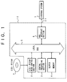
- a compact disc read only memory (CD-ROM) drive apparatus 10 which is an embodiment of the present invention comprises a CD-ROM read control section 2 for reading information recorded on a CD-ROM 1, a central processing section 3 for processing data obtained by the CD-ROM read control section 2, and the like, a buffer memory 4 for storing the data obtained by the CD-ROM read control section 2, and a bus interface section 6 connected to a system 7 located outside of the CD-ROM drive apparatus 10.
- the components in the CD-ROM drive apparatus 10 are connected to each other by a local bus 5.
- a plurality of data sets each including data of a predetermined length and error correcting codes used for correcting errors within the data, are recorded on the CD-ROM in advance. More specifically, as mentioned above, the data of one sector (herein after referred to as "a sector data set”) includes 12 bytes of synchronization data, 4 bytes of header data, 2048 bytes of user data and 288 bytes of auxiliary data.
- the CD-ROM read control section 2 includes an optical pickup (not shown), a pickup drive device (not shown) for driving the optical pickup, and a control circuit (not shown) for transforming optical signals into electrical signals so as to obtain desired data.
- the central processing section 3 is constituted using a SH7034 microcomputer manufactured by Hitachi, Ltd.
- This microcomputer comprises a RISC type central processing unit (CPU) and necessary peripheral circuits including a 64 K byte read only memory (ROM), a 4 K byte random access memory, a direct memory access controller (DMAC), a timer, a serial communication interface (SCI), an analog-to-digital converter, an interrupt controller, an in/out (I/O) port and the like. It is operated by programs stored in the ROM.
- the external system 7 for example, is a personal computer which uses the information recorded on the CD-ROM 1.
- the central processing section 3 supplies the CD-ROM read control section 2 with a predetermined instruction based on the provided data transfer request to obtain the desired data.
- the pickup drive device of the CD-ROM read control section 2 moves the optical pickup into the vicinity of the target track of the CD-ROM 1 in accordance with the supplied instruction. After the optical pickup reaches the vicinity thereof, a light beam from a light emitting element (not shown) provided in the optical pickup is directed onto the CD-ROM 1, and the light reflected from the CD-ROM 1 is received by a light receiving element (not shown).
- the control circuit obtains sector data sets corresponding to the requested sectors.
- the CD-ROM drive apparatus 10 of this embodiment it takes approximately 6.7 milliseconds to read the information corresponding to one sector data set.
- the CD-ROM drive apparatus is arranged to read the information recorded on the CD-ROM 1 at double the standard speed.
- the CD-ROM drive apparatus may read the information recorded thereon at the standard speed, namely, it may take 13.3 milliseconds to read the information corresponding to one sector data set.
- the CD-ROM drive apparatus may read it at another speed such as triple speed.
- the CD-ROM read control section 2 carries out error correction using CIRC and error detection using EDC with respect to the obtained data.
- the processed data are transferred via the local bus 5 to the buffer memory 4, and are stored in predetermined areas thereof.
- the central processing section 3 carries out error correction using LECC with respect to the data stored in the predetermined areas of the buffer memory 4, if the errors remain after the error correction using the CIRC, or other errors occur owing to the error correction using the CIRC and these errors are detected by the error detection using the EDC.
- the central processing section 3 stores the obtained data in other predetermined areas of the buffer memory 4.
- the data stored in the other predetermined areas thereof are supplied via the local bus 5 to the bus interface section 6 under the control of the central processing section 3. Further the data in the bus interface section 6 are transferred to the external system 7 via the external system bus 21.
- the central processing section 3 conduct other operations such as storing the data obtained by the CD-ROM read control section 2 in the predetermined areas of the buffer memory 4, reading the sector data set stored in other predetermined areas of the buffer memory 4 to correct errors within the data set and transferring the sector data set via the local bus 5 to the bus interface section 6, and other processing required to operate the CD-ROM drive apparatus.
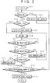
- the central processing section 2 determines whether or not one or more areas in the buffer memory 4 can be secured as a temporary buffer for temporarily storing a sector data set obtained by the CD-ROM read control section 2 (step 202).
- step 202 finds that no area for temporarily storing the sector data set is available in the buffer memory 4, the processing proceeds to the step 203. On the contrary, if the areas are found, they are ensured for the temporary buffer.
- the central processing section 3 supplies the CD-ROM read control section 2 with an instruction to maintain the position of the optical pickup.
- the central processing section 3 determines whether or not the optical pickup of the CD-ROM read control section 2 has reached the vicinity of the target track and has read information recorded on the predetermined position of the CD-ROM 1. If the result is "YES” in the step 204, the processing proceeds to the step 206, while if "NO,” the central processing section 3 supplies the CD-ROM read control section 2 with an instruction to initiate reading of information recorded on the CD-ROM 1 (step 205).
- the central processing section 3 gives predetermined information to the built-in DMAC so as to transfer to the temporary buffer the sector data set processed in the CD-ROM read control section 2 by, for example, error correction using the CIRC and error detection using the EDC (step 206).
- the information given to the DMAC includes the source (the CD-ROM read control section), the destination (addresses of the temporary buffer), and the number of data to be transferred (size of one sector data set).
- the central processing section 3 determines whether or not the sector data set is transferred to the temporary buffer provided in the buffer memory 4 and is stored therein by the DMAC (step 207). More specifically, this step is accomplished by the DMAC sending a transfer completion flag to the CPU of the central processing section 3. If the transfer of the sector data set is not finished, the processing returns to the step 207, while if the transfer is finished, it proceeds to the step 208.
- the central processing section 3 determines whether or not the data set is associated with the desired sector (step 208). If the result is "NO” in the step 208, the central processing section 3 frees the temporary buffer, and the processing returns to the step 206 so that another sector data set associated with another sector is read (step 209). On the contrary, if the result is "YES” in the step 208, the central processing section 3 determines whether or not the sector data set contains any errors based on the result of the error detection using the EDC carried out by the CD-ROM read control section 2 (step 210).
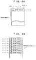
- FIG. 4A shows an example of the contents of the temporary buffer. As shown in Figure 4A, an error flag corresponds to one sector data set.
- the temporary buffer 400 is formed with a data set 410-1 consisting of an error flag 401-1 and a sector data set 402-1.
- the central processing section 3 determines whether or not the sector data sets of all sectors specified by the external system 7 have been obtained (step 212). If the result is "YES” in the step 212, the central processing section 3 supplies the CD-ROM read control section 2 with an instruction to terminate the reading of information recorded on the CD-ROM 1 while maintaining the position of the optical pickup (step 213). On the other hand, if the result is "NO” in the step 212, the processing returns to the step 202 to secure other space areas in the buffer memory 4 as the temporary buffer.
- the sector data sets of predetermined sectors are stored in the temporary buffer of the buffer memory 4.
- Figure 4B shows the sector data sets stored in the temporary buffer provided in the buffer memory 4 owing to the processing shown in Figure 2.
- the temporary buffer 400 includes, in addition to the first data set 410-1 consisting of the error flag 401-1 and the sector data set 402-1, the second to seventh data sets 410-2 to 410-7.
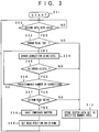
- the central processing section 3 carries out the processing shown in Figure 3 if at least one data set exists in the temporary buffer of the buffer memory 4, as when the DMAC has caused data to be transferred from the CD-ROM read control section 2 to the temporary buffer of the buffer memory 4 (see the steps 301, 302).
- the central processing section 3 determines whether or not the data set consisting of the error flag and the sector data set exist (step 302). If the result is "YES” in the step 302, the central processing section 3 reads the data set positioned at the front of the temporary buffer and determines whether or not the error flag thereof is "1" or "ON” (step 303). On the other hand, if the result is "NO” in the step 302, the step 302 is repeated. The data set positioned at the front is the earliest stored data set in the temporary buffer.
- step 303 determines that the error flag is "0" or "OFF,” the processing proceeds to the step 310, while if it determines that the error flag is "1” or "ON,” the processing proceeds to the step 304.
- the error correction using the LECC is carried out with respect to the data set in order of the error correction by the parities P and Q.
- the central processing section 3 determines whether or not the data set after the error correction still contains any errors (step 305). If the data set contains any errors, the central processing section 3 further determines whether or not the number of error corrections has reached a predetermined number (step 306). If the number thereof has not reach the predetermined number, the processing returns to the step 304, while if it has reached the predetermined number, the processing proceeds to the step 307.
- step 307 determines that the information recorded on the CD-ROM 1 is to be read again because the error correction cannot be completed even by the error correction using the LECC ("YES" in the step 307), the processing proceeds to the step 308, otherwise it proceeds to the step 310.
- step 305 If the result is "NO" in the step 305, namely, if it is determined that the data set after the error correction using the LECC contains no error, the processing proceeds to the step 310.
- the central processing section 3 frees the temporary buffer to again read information recorded on the CD-ROM 1 (step 308), and again supplies the CD-ROM read control section 2 with the instruction to read the information recorded on the CD-ROM 1 (step 309).
- the sector data set read out from the temporary buffer in the step 303 is stored in other predetermined areas in the buffer memory 4 secured as a specified memory area (step 310).
- the sector data set after the error correction is stored in the specified memory area (step 310).
- the processing shown in Figure 2 is carried out on an interrupt basis and is activated when an interrupt is applied to the CPU of the central processing section 3 during the execution period of the processing shown in Figure 3.
- the CPU of the central processing section 3 after giving the predetermined information to the DMAC, the CPU of the central processing section 3 enables the processing shown in Figure 3.
- the CPU of the central processing section 3 is interrupted by the transfer completion flag indicative of the completion of the transfer of the sector data set provided by the DMAC, whereby the processing from the step 208 on is carried out.
- areas in the temporary buffer 4 are secured as the temporary buffer for storing at least one data set consisting of a sector data set and an error flag obtained by the CD-ROM read control section 2. Another areas therein are ensured for the specified memory area for storing at least one sector data set containing no error.
- the buffer memory 4 is used for the above mentioned temporary buffer and the specified memory area. Other areas in the buffer memory are space areas.
- the error correction using the LECC is carried out by the central processing section 3 (step 304).
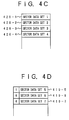
- the process shown in Figure 3 is carried out with respect to the second data set 410-2. Since the error flag in the second data set 410-2 is "0 (zero)," in the processing shown in Figure 3 with respect to this data set, the central processing section 3 determines "NO" in the step 303, which causes the sector data set in the second data set 410-2 to be stored in the specified memory area. As in the processing with respect to the second data set, in the processing shown in the Figure 3 with respect to the third and fourth data sets, sector data sets in the third and fourth data sets are stored in the specified memory area.
- Figure 4C shows the first sector data set 420-1 to the fourth sector data set 420-4 stored in the specified memory area.
- the sector data set can be transferred from the CD-ROM read control section 2 to the temporary buffer of the buffer memory 4.
- the CD-ROM read control section 2 can continuously read the information recorded on the CD-ROM 1.
- the central processing section 3 includes a memory management table to manage link information concerning areas of the temporary buffer and specified memory area with respect to the individual data sets including sector data sets.
- the processing of the step 310 is not accomplished by actually transferring the sector data set stored in the temporary buffer to the specified memory area, but by rewriting the link information of the information management table. Accordingly, the time required to carry out the step 310 is very short. As a result it is possible to further reduce the processing time of the error correction.
- the freeing of the temporary buffer (steps 209, 208) is also accomplished by rewriting the link information of the information management table.
- the specified memory area Since the specified memory area is established in the buffer memory 4 by rewriting the link information of the information management table, the specified memory area also changes dynamically and is not always a successive area.
- the temporary buffer 4 is used as the temporary buffer and the specified memory area, it is possible to reduce the memory capacity and the number of semiconductor memories.
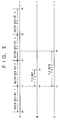
- Figure 5 shows the timing of the transfer of the data by the DMAC and that of the error correction by the central processing section 3 when the information recorded on the CD-ROM 1 is read at double speed.
- the time T1 required to read out from the CD-ROM 1 the information corresponding to one sector data set is approximately 6.7 milliseconds (150 sectors/sec).
- the error correction using the LECC is activated at approximately t1.
- the SH7034 microcomputer which is the CPU provided in the central processing section 3 operates at a clock speed of 20 MHz, it takes approximately 4.4 milliseconds to carry out the error correction by the parities P and Q in succession (see time T2 on the time axis B).
- the error correction by the central processing section 3 is completed by the time t2 at which the transfer of the second sector data set to the temporary buffer is completed, so far as the error correction by the parities P and Q is carried out successively. Accordingly, in the conventional CD-ROM drive apparatus to which the present invention is not applied, it is possible to continuously read the information recorded on the CD-ROM without causing the apparatus to go into pause status.
- the conventional CD-ROM drive apparatus to which the present invention is not applied has to suspend reading of the information and go into the pause status.
- the CD-ROM drive apparatus which is an embodiment of the present invention, since the sector data sets are transferred to the temporary buffer of the buffer memory 4 to be stored therein independently of the error correction using the LECC by the central processing section 3, the apparatus need not enter the pause status even if the error correction using the LECC is carried out several times. As a result, it is possible to prevent a time loss from occurring owing to the CD-ROM drive apparatus being put in the pause status and then activated again to initiate reading of the information.
- the buffer memory 4 is capable of storing data of 200 sectors (approximately 470 K bytes).
- the error rate of random byte errors is extremely small. Consequently, there is very little risk of the buffer memory 4 overflowing with data.
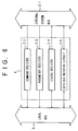
- the bus interface 6 includes a command register 22 for storing data transfer requests or the like received from the external system 7 via the external system bus 21, a parameter register 23 for storing information accompanying the information supplied to the command register 22, a status register 24 for storing information indicative of the operational status of the CD-ROM drive apparatus, and a data bus matching circuit 25 which transforms data in the local bus 5 and in the external bus 21 into data adapted to each other.
- the data transfer request is supplied via the external system bus 21 to the command register 22 and stored therein. If there exists a control parameter accompanying the data transfer request, it is supplied via the external system bus 21 to the parameter register 23 to be stored therein.
- the central processing section 3 reads the contents of the command register 22. If the accompanying parameter is required, the central processing section 3 reads the contents of the parameter register 23 to obtain the control parameter.
- the operational status of the CD-ROM drive apparatus is supplied to the status register 24 by the central processing section 3, and is further transferred via the external system bus 21 to the external system 7.
- Two types of operational status are established, one of which is a hardware status generated by logic circuits and the other of which is a software status managed by software of the central processing section 3. Since the hardware status is automatically generated by the logic circuit, if it changes, the central processing section 3 has to read it to determine the contents thereof. On the contrary, since the software status is stored in a register in the central processing section 3, during the execution period of the software by the central processing section 3, it suffices to write the software status into the status register 24 only when it changes.
- One or more sector data sets after error correction by the central processing section 3 or data sets not subjected to the error correction by the central processing section 3 because they contain no error, which are read out from the specified memory area of the buffer memory 4, are supplied via the local bus 5 to the data bus matching circuit 25.
- the data bus matching circuit 25 converts the supplied data into data adapted to the external bus 21 and transfers the latter to the external system 7 via the external bus 21.
- the parameter register can be eliminated.
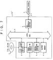
- CD-ROM drive apparatus which is a second embodiment of the present invention will now be explained. As shown in Figure 7, the structure of the CD-ROM drive apparatus 10' is analogous to that of the first embodiment except that it additionally includes an error correction circuit 11.
- the error correction circuit 11 is constructed by hardware and includes a work memory (not shown) used for error correction.
- the error correction circuit 11 carries out the error correction using LECC with respect to sector data sets obtained by a CD-ROM read control memory 2.
- the time required to complete the error correction with respect to one sector data set is constant, and is less than the time required to read out information corresponding to one sector data set from a CD-ROM 1.
- the sector data set obtained by the CD-ROM read control memory 2 is temporarily stored in the work memory provided in the error correction circuit 11.
- the error correction using the LECC is carried out by the error correction circuit 11, whereafter the sector data set after error correction is transferred to a temporary buffer of a buffer memory 4.
- an error flag with respect to the sector data set concerning the processing is set. The error flag is used for determining whether or not the central processing section 3 carries out the error correction using the LECC.
- the second embodiment is different from the first embodiment in that the error correction using the LECC is preliminarily carried out by the error correction circuit 11 before the sector data set obtained by the CD-ROM read control section 2 is transferred to the temporary buffer of the buffer memory 4.
- the error correction circuit 11 need not have a high error correction capability. Since the structure of the error correction section 11 is therefore relatively simple, it can be easily designed and manufactured at a low cost. As mentioned above, since the error rate of random byte errors is very small, most of the errors can be corrected by the error correction circuit 11. Even if the sector data set contains so many errors that the error detection circuit 11 cannot completely correct them, since the central processing section 3 carries out the error correction using the LECC after the sector data set is transferred to the temporary buffer, lowering of the reliability of eventually obtained data is prevented. On the contrary, in the second embodiment, since the error correction circuit 11 can correct most of the errors, it is possible to reduce the error correction load using the LECC by the central processing section 3, which increases the time available for managing the CD-ROM drive apparatus by the central processing section 3.
- the present invention is applied to correct errors within data obtained based on information recorded on a CD-ROM in a CD-ROM drive apparatus, it is instead possible to apply the present invention to correct errors within data obtained based on information from other information storage media such as an optical disk.
- the optical pickup, the pickup drive device and the like of the CD-ROM read control section 2 may be modified.
- the central processing section 3 activates the processing shown in Figure 3 if at least one sector data set exists in the temporary buffer of the buffer memory 4, and the error correction using the LECC is carried out if necessary, the invention is not limited to this arrangement. It is instead possible to determine when the error correction using the LECC is initiated based on the importance of other processing for controlling the CD-ROM drive apparatus and the time period required to complete the other processing.
- space areas in the buffer memory 4 are secured as the temporary buffer or the specified memory area
- the invention is not limited to this arrangement. It is instead possible to define areas used for the temporary buffer and the specified memory area in advance.
- the respective means need not necessarily be physical means and arrangements whereby the function of the respective means is accomplished by software fall within the scope of the present invention.
- the function of a single means may be accomplished by two or more physical means and the function of two or more means may be accomplished by a single physical means.
Landscapes
- Engineering & Computer Science (AREA)
- Signal Processing (AREA)
- Signal Processing For Digital Recording And Reproducing (AREA)
Applications Claiming Priority (3)
| Application Number | Priority Date | Filing Date | Title |
|---|---|---|---|
| JP24366894 | 1994-10-07 | ||
| JP6243668A JPH08106733A (ja) | 1994-10-07 | 1994-10-07 | 情報記憶媒体利用システム |
| JP243668/94 | 1994-10-07 |
Publications (3)
| Publication Number | Publication Date |
|---|---|
| EP0706184A2 true EP0706184A2 (de) | 1996-04-10 |
| EP0706184A3 EP0706184A3 (de) | 1997-01-08 |
| EP0706184B1 EP0706184B1 (de) | 2001-05-30 |
Family
ID=17107225
Family Applications (1)
| Application Number | Title | Priority Date | Filing Date |
|---|---|---|---|
| EP95115877A Expired - Lifetime EP0706184B1 (de) | 1994-10-07 | 1995-10-09 | Fehlerkorrekturgerät |
Country Status (4)
| Country | Link |
|---|---|
| US (2) | US5768502A (de) |
| EP (1) | EP0706184B1 (de) |
| JP (1) | JPH08106733A (de) |
| DE (1) | DE69521097T2 (de) |
Families Citing this family (15)
| Publication number | Priority date | Publication date | Assignee | Title |
|---|---|---|---|---|
| JPH08106733A (ja) * | 1994-10-07 | 1996-04-23 | Hitachi Ltd | 情報記憶媒体利用システム |
| JP3589802B2 (ja) * | 1996-08-22 | 2004-11-17 | パイオニア株式会社 | 情報記録方法及び装置 |
| JP3271181B2 (ja) * | 1998-11-09 | 2002-04-02 | インターナショナル・ビジネス・マシーンズ・コーポレーション | ディスクドライブ装置、ディスクドライブ装置のエラー回復処理方法及びディスクドライブ制御装置 |
| US6304993B1 (en) | 1998-12-14 | 2001-10-16 | Lsi Logic Corporation | Method and apparatus for performing efficient reseeks in an optical storage device |
| JP2000242440A (ja) * | 1999-02-25 | 2000-09-08 | Alps Electric Co Ltd | ディスク装置 |
| JP2001075864A (ja) * | 1999-09-02 | 2001-03-23 | Fujitsu Ltd | キャッシュ制御装置 |
| US6651184B1 (en) * | 1999-11-03 | 2003-11-18 | Hewlett-Packard Development Company, L.P. | Isochronous transfer mode on a universal serial bus with error correction algorithms |
| US6601019B1 (en) * | 1999-11-16 | 2003-07-29 | Agilent Technologies, Inc. | System and method for validation of objects |
| US6941488B2 (en) * | 2000-08-04 | 2005-09-06 | Seagate Technology Llc | Retrieval of a single complete copy from multiple stored copies of information |
| US6701451B1 (en) * | 2000-08-11 | 2004-03-02 | Emc Corporation | Selective correction of data errors |
| JP3708064B2 (ja) * | 2002-05-31 | 2005-10-19 | 株式会社東芝 | ディスク記憶装置、ディスクコントローラ及び同装置に適用するエラー訂正方法 |
| KR100860985B1 (ko) * | 2003-05-23 | 2008-09-30 | 삼성전자주식회사 | 패딩 정보를 이용한 기록/재생 방법 |
| JP3666665B2 (ja) * | 2003-08-21 | 2005-06-29 | パイオニア株式会社 | 情報記録方法及び装置 |
| US7536625B2 (en) * | 2004-06-30 | 2009-05-19 | Seagate Technology Llc | Maintaining data integrity in a data storage system |
| JP5007676B2 (ja) * | 2008-01-31 | 2012-08-22 | 富士通株式会社 | 符号化装置、復号化装置、符号化・復号化装置及び記録再生装置 |
Citations (1)
| Publication number | Priority date | Publication date | Assignee | Title |
|---|---|---|---|---|
| JPH05218883A (ja) | 1992-02-06 | 1993-08-27 | Kyocera Corp | 復号回路 |
Family Cites Families (24)
| Publication number | Priority date | Publication date | Assignee | Title |
|---|---|---|---|---|
| US4604750A (en) * | 1983-11-07 | 1986-08-05 | Digital Equipment Corporation | Pipeline error correction |
| US4866717A (en) * | 1986-07-29 | 1989-09-12 | Matsushita Electric Industrial Co., Ltd. | Code error detecting and correcting apparatus |
| US4949342A (en) * | 1987-04-14 | 1990-08-14 | Matsushita Electric Industrial Co., Ltd. | Code error detecting method |
| AU622626B2 (en) * | 1987-06-03 | 1992-04-16 | Sony Corporation | Method of processing data |
| DE3856035T2 (de) * | 1987-08-24 | 1998-02-26 | Quantum Corp | Schaltung mit grosser bandbreite und verfahren zur reed-solomon-kodierung, dekodierung und fehlerkorrektur |
| US5239636A (en) * | 1988-09-09 | 1993-08-24 | Advanced Micro Devices, Inc. | Buffer memory subsystem for peripheral controllers |
| US5038275A (en) * | 1988-10-07 | 1991-08-06 | Advanced Micro Devices, Inc. | Status transfer structure within a data processing system with status read indication |
| JP2554743B2 (ja) * | 1989-05-19 | 1996-11-13 | シャープ株式会社 | 再生のための誤り訂正装置 |
| US5058116A (en) * | 1989-09-19 | 1991-10-15 | International Business Machines Corporation | Pipelined error checking and correction for cache memories |
| US5164944A (en) * | 1990-06-08 | 1992-11-17 | Unisys Corporation | Method and apparatus for effecting multiple error correction in a computer memory |
| JPH04139666A (ja) * | 1990-09-30 | 1992-05-13 | Ricoh Co Ltd | 追記型光デイスクの信号処理用半導体集積回路および半導体装置 |
| JPH0521883A (ja) * | 1991-07-11 | 1993-01-29 | Pioneer Electron Corp | 出力制御装置 |
| JPH05225714A (ja) * | 1992-02-17 | 1993-09-03 | Sony Corp | デジタル信号処理装置 |
| JPH05265939A (ja) * | 1992-03-23 | 1993-10-15 | Toshiba Corp | データ転送装置 |
| JP3260421B2 (ja) * | 1992-06-30 | 2002-02-25 | パイオニア株式会社 | Cd−rom再生装置 |
| JP3263793B2 (ja) * | 1992-10-31 | 2002-03-11 | ソニー株式会社 | 光デイスク再生装置 |
| US5499252A (en) * | 1992-11-20 | 1996-03-12 | Sanyo Electric Co., Ltd. | CD-ROM decoder having means for reading selected data from a CD into a memory |
| US5432801A (en) * | 1993-07-23 | 1995-07-11 | Commodore Electronics Limited | Method and apparatus for performing multiple simultaneous error detection on data having unknown format |
| US5602857A (en) * | 1993-09-21 | 1997-02-11 | Cirrus Logic, Inc. | Error correction method and apparatus |
| EP0689208A1 (de) * | 1994-06-23 | 1995-12-27 | Oak Technology Inc. | Verfahren zur blockorientierten Adressierung |
| JP3637604B2 (ja) * | 1994-06-29 | 2005-04-13 | ソニー株式会社 | 情報再生装置及び方法 |
| US5509119A (en) * | 1994-09-23 | 1996-04-16 | Hewlett-Packard Company | Fast comparison method and apparatus for error corrected cache tags |
| JPH08106733A (ja) * | 1994-10-07 | 1996-04-23 | Hitachi Ltd | 情報記憶媒体利用システム |
| US5630055A (en) * | 1995-05-05 | 1997-05-13 | Digital Equipment Corporation | Autonomous pipeline reconfiguration for continuous error correction for fills from tertiary cache or memory |
-
1994
- 1994-10-07 JP JP6243668A patent/JPH08106733A/ja active Pending
-
1995
- 1995-10-06 US US08/539,884 patent/US5768502A/en not_active Expired - Fee Related
- 1995-10-09 DE DE69521097T patent/DE69521097T2/de not_active Expired - Fee Related
- 1995-10-09 EP EP95115877A patent/EP0706184B1/de not_active Expired - Lifetime
-
1998
- 1998-04-28 US US09/066,911 patent/US6088825A/en not_active Expired - Fee Related
Patent Citations (1)
| Publication number | Priority date | Publication date | Assignee | Title |
|---|---|---|---|---|
| JPH05218883A (ja) | 1992-02-06 | 1993-08-27 | Kyocera Corp | 復号回路 |
Also Published As
| Publication number | Publication date |
|---|---|
| US5768502A (en) | 1998-06-16 |
| US6088825A (en) | 2000-07-11 |
| EP0706184B1 (de) | 2001-05-30 |
| DE69521097T2 (de) | 2001-11-08 |
| DE69521097D1 (de) | 2001-07-05 |
| JPH08106733A (ja) | 1996-04-23 |
| EP0706184A3 (de) | 1997-01-08 |
Similar Documents
| Publication | Publication Date | Title |
|---|---|---|
| US6088825A (en) | Error correcting apparatus with error correction unit carrying out first error correction and CPU configured to carry out second error correction | |
| EP0587437B1 (de) | Datenkompression/-dekompression und Speicherung von komprimierten und nicht komprimierten Daten in einem einzigen Datenspeichervolumen | |
| EP0703581B1 (de) | Verfahren zur Vorverarbeitung, Verfahren zum Lesen/Schreiben von Informationen, Ein-/Ausgabevorrichtung und Lese-/Schreibvorrichtung | |
| US4562577A (en) | Shared encoder/decoder circuits for use with error correction codes of an optical disk system | |
| US5414570A (en) | Tape marks recorded in user data blocks having identifications of the recorded tape marks | |
| US5200864A (en) | Combining small records into a single record block for recording on a record media | |
| US6119260A (en) | Decoder for executing error correction and error detection in parallel | |
| US5953513A (en) | Recording and reproducing device for recording and reproducing information from different kinds of storage media having different sector formats | |
| WO2001020607A1 (en) | Signal processor for correcting and detecting errors | |
| US5499252A (en) | CD-ROM decoder having means for reading selected data from a CD into a memory | |
| US5535327A (en) | Method and apparatus for communicating formatted data from a mass storage device to a host computer | |
| JPS62298970A (ja) | シ−ケンシャルバッファ装置 | |
| US6243845B1 (en) | Code error correcting and detecting apparatus | |
| US6505319B1 (en) | Signal processing circuit and information recording apparatus | |
| US6546475B1 (en) | Disc controller, disc control system, and disc controlling method | |
| US5761220A (en) | Minimum latency asynchronous data path controller in a digital recording system | |
| JP3524828B2 (ja) | 符号誤り訂正検出装置 | |
| US6304993B1 (en) | Method and apparatus for performing efficient reseeks in an optical storage device | |
| JP2001273710A (ja) | Cd−romデコーダ | |
| KR100234391B1 (ko) | 디지털 비디오 디스크 시스템의 ecc 메모리 제어장치 | |
| JPS63237264A (ja) | 情報記録方式 | |
| TW425545B (en) | Coding error correction detection device | |
| JP3427051B2 (ja) | 符号誤り検出回路 | |
| JPH1116298A (ja) | 符号誤り訂正検出装置 | |
| KR20010093708A (ko) | Cd-rom 디코더 |
Legal Events
| Date | Code | Title | Description |
|---|---|---|---|
| PUAI | Public reference made under article 153(3) epc to a published international application that has entered the european phase |
Free format text: ORIGINAL CODE: 0009012 |
|
| 17P | Request for examination filed |
Effective date: 19951009 |
|
| AK | Designated contracting states |
Kind code of ref document: A2 Designated state(s): DE GB NL |
|
| PUAL | Search report despatched |
Free format text: ORIGINAL CODE: 0009013 |
|
| AK | Designated contracting states |
Kind code of ref document: A3 Designated state(s): DE GB NL |
|
| 17Q | First examination report despatched |
Effective date: 19990301 |
|
| GRAG | Despatch of communication of intention to grant |
Free format text: ORIGINAL CODE: EPIDOS AGRA |
|
| GRAG | Despatch of communication of intention to grant |
Free format text: ORIGINAL CODE: EPIDOS AGRA |
|
| GRAH | Despatch of communication of intention to grant a patent |
Free format text: ORIGINAL CODE: EPIDOS IGRA |
|
| GRAH | Despatch of communication of intention to grant a patent |
Free format text: ORIGINAL CODE: EPIDOS IGRA |
|
| GRAA | (expected) grant |
Free format text: ORIGINAL CODE: 0009210 |
|
| AK | Designated contracting states |
Kind code of ref document: B1 Designated state(s): DE GB NL |
|
| REF | Corresponds to: |
Ref document number: 69521097 Country of ref document: DE Date of ref document: 20010705 |
|
| REG | Reference to a national code |
Ref country code: GB Ref legal event code: IF02 |
|
| PLBE | No opposition filed within time limit |
Free format text: ORIGINAL CODE: 0009261 |
|
| STAA | Information on the status of an ep patent application or granted ep patent |
Free format text: STATUS: NO OPPOSITION FILED WITHIN TIME LIMIT |
|
| 26N | No opposition filed | ||
| PGFP | Annual fee paid to national office [announced via postgrant information from national office to epo] |
Ref country code: NL Payment date: 20030924 Year of fee payment: 9 Ref country code: GB Payment date: 20030924 Year of fee payment: 9 |
|
| PGFP | Annual fee paid to national office [announced via postgrant information from national office to epo] |
Ref country code: DE Payment date: 20031203 Year of fee payment: 9 |
|
| PG25 | Lapsed in a contracting state [announced via postgrant information from national office to epo] |
Ref country code: GB Free format text: LAPSE BECAUSE OF NON-PAYMENT OF DUE FEES Effective date: 20041009 |
|
| PG25 | Lapsed in a contracting state [announced via postgrant information from national office to epo] |
Ref country code: NL Free format text: LAPSE BECAUSE OF NON-PAYMENT OF DUE FEES Effective date: 20050501 |
|
| PG25 | Lapsed in a contracting state [announced via postgrant information from national office to epo] |
Ref country code: DE Free format text: LAPSE BECAUSE OF NON-PAYMENT OF DUE FEES Effective date: 20050503 |
|
| GBPC | Gb: european patent ceased through non-payment of renewal fee |
Effective date: 20041009 |
|
| NLV4 | Nl: lapsed or anulled due to non-payment of the annual fee |
Effective date: 20050501 |