EP0706428B1 - Verfahren und vorrichtung zum biegen von messerband - Google Patents
Verfahren und vorrichtung zum biegen von messerband Download PDFInfo
- Publication number
- EP0706428B1 EP0706428B1 EP94919309A EP94919309A EP0706428B1 EP 0706428 B1 EP0706428 B1 EP 0706428B1 EP 94919309 A EP94919309 A EP 94919309A EP 94919309 A EP94919309 A EP 94919309A EP 0706428 B1 EP0706428 B1 EP 0706428B1
- Authority
- EP
- European Patent Office
- Prior art keywords
- rule
- steel rule
- steel
- gripping
- control
- Prior art date
- Legal status (The legal status is an assumption and is not a legal conclusion. Google has not performed a legal analysis and makes no representation as to the accuracy of the status listed.)
- Expired - Lifetime
Links
Images





Classifications
-
- B—PERFORMING OPERATIONS; TRANSPORTING
- B21—MECHANICAL METAL-WORKING WITHOUT ESSENTIALLY REMOVING MATERIAL; PUNCHING METAL
- B21D—WORKING OR PROCESSING OF SHEET METAL OR METAL TUBES, RODS OR PROFILES WITHOUT ESSENTIALLY REMOVING MATERIAL; PUNCHING METAL
- B21D37/00—Tools as parts of machines covered by this subclass
- B21D37/20—Making tools by operations not covered by a single other subclass
- B21D37/205—Making cutting tools
-
- B—PERFORMING OPERATIONS; TRANSPORTING
- B21—MECHANICAL METAL-WORKING WITHOUT ESSENTIALLY REMOVING MATERIAL; PUNCHING METAL
- B21D—WORKING OR PROCESSING OF SHEET METAL OR METAL TUBES, RODS OR PROFILES WITHOUT ESSENTIALLY REMOVING MATERIAL; PUNCHING METAL
- B21D5/00—Bending sheet metal along straight lines, e.g. to form simple curves
- B21D5/04—Bending sheet metal along straight lines, e.g. to form simple curves on brakes making use of clamping means on one side of the work
- B21D5/042—With a rotational movement of the bending blade
-
- Y—GENERAL TAGGING OF NEW TECHNOLOGICAL DEVELOPMENTS; GENERAL TAGGING OF CROSS-SECTIONAL TECHNOLOGIES SPANNING OVER SEVERAL SECTIONS OF THE IPC; TECHNICAL SUBJECTS COVERED BY FORMER USPC CROSS-REFERENCE ART COLLECTIONS [XRACs] AND DIGESTS
- Y10—TECHNICAL SUBJECTS COVERED BY FORMER USPC
- Y10S—TECHNICAL SUBJECTS COVERED BY FORMER USPC CROSS-REFERENCE ART COLLECTIONS [XRACs] AND DIGESTS
- Y10S72/00—Metal deforming
- Y10S72/702—Overbending to compensate for springback
Definitions
- This invention is a totally automated process and apparatus for producing steel rule dies, which are made from edge-sharpened strip metal .
- the dies so produced may have complex shapes, which are created as a series of two-dimensional bends, each bend being at a precise angle, and at a precise location along the length of the rule stock.
- the process utilizes a system including stand-alone units designed to take reeled strip and uniformly unwind it, a drive and measuring unit which accurately tracks the motion of the strip forward and backward, and produces locational information in the form of a digital electrical signal, a dual directional bending head which bends the strip as required, a video position sensing unit which precisely determines the shape of the die as it exits from the bending head, a cutoff shear and notcher which cuts the die components to final size, and finally, a computation and control system which synchronizes the entire operation.
- the collection of separable units are integrated, and the process is controlled by the programmable computation and control system, which contains a data bank having information on the specific elastic response of the current spool of rule and/or generalized elasticity data. This data is used to predict the correction required in making each bend, in order to take into account the spring back, or hysterisis, of the material.
- the video position sensing unit determines the exact shape of the bend after it is made, and produces an electrical signal containing this information, which is fed into the computation and control system.
- the computation and control system calculates the variations between the actual shape and the desired shape, and issues a control signal to modify the next bend accordingly.
- Steel rule dies are used in cutting many of the fabricated items we take for granted.
- the materials cut by dies range from soft metals and tough plastics through foams, leathers, and cloth, to frail films, papers and even food items.
- the end products of this type of die cutting include thick foam cushions, shoe parts, decals, metal foil trays, and bakeware.
- any product that can be produced in sheet form may be cut with steel rule dies.
- Other similar die types such as clickers, can be made with the same methods as steel rule dies, although the die material may be slightly different.
- the steel rule industry is presently estimated to produce revenues of between four hundred million and six hundred million dollars per year.
- the formed steel rule dies are usually either pressed into laser cut grooves or into intricately sawn slots in a plywood base, and must be formed to fit the slots.
- the alignment of parts by mere use of the slots as guides is rarely successful if the shape of the rule is not pre-formed to conform to the shape of the slots.
- a frequently used technique provides for frequent lands in the plywood parts that hold the centers of cutouts within the die frames. The lands are accommodated by cutting matching notches into the steel strip so that the strip goes over the lands without making contact.
- the dies are made from any of a series of specialty steels.
- the stock is formed into a coiled strip and then sharpened on one edge of the strip.
- the coils are difficult to handle, so the strips are usually supplied in a flat cutoff form.
- the die is constructed from one or more sections of this strip and may be bent at various sharp angles, or into gradual curves, or used as straight sections, depending on the desired shape. While the use of steel rule dies is not the only way to make repetitive and essentially identical cut shapes, such use constitutes one of the lowest cost and most popular methods.
- the steel rule dies are made by bending strips of the edge-sharpened steel into the required intricate shapes.
- the formed strip is then attached to a backing that permits pressure to be applied by a press or powered stamping machine to cut out the materials.
- the bending is sometimes done by hand, or, at other times by machine. Regardless of the method of manufacture, making the bends requires the skill of experienced artisans because the steel strip, as it is bent, tends to spring back, due to the elastic properties of steel.
- this machine can make only 50 to 60% of the simpler needed bends.
- the prior art also contains a number of wire benders. These devices are designed to handle either wire ends in electrical/electronic assembly operations (which have little in common with the diverse requirements of a strip bending) or they are designed to bend wire shapes. They are generally not applicable to the current application.
- a general object of the current invention is to provide an effective, economical, automated means of producing steel rule dies from a continuous coil of raw material.
- a specific object of the current invention is to reduce the high amount waste that is now common in die manufacture.
- a second specific object of the current invention is to provide an accurate, repeatable method of die manufacture, which automatically compensates for differences in the physical characteristics between different lots of the steel rule stock from which the dies are made, and for inaccuracies in the machine construction.
- the invention does away with the necessity for the repeated test and correction techniques currently incorporated in steel die manufacture. It further dispenses with the need for highly skilled operators to perform said test and corrective techniques.
- the invention accomplishes these objectives by the use of responsive bending techniques which repeatedly make an incremental bend and then automatically examine the results, thereafter correcting the next portion of the bend to compensate for the accumulated error.
- One aspect of the current invention provides for the bending of the steel rule in two directions with a single bending head, thus lowering equipment costs and complexity.
- Another aspect of the invention allows a variety of notches to be made along the strip, and cutoffs to be made near bends, thus minimizing the scrap which would otherwise be produced.
- Yet another aspect of the invention produces mitered corners when needed.
- the process of making steel rule dies disclosed in this invention involves the use of a bending head which includes a single small-diameter mandrel which is used to distort the steel rule strips by the application of force on the protruding portion of the strip while it is firmly gripped in a holding jaw.
- the single mandrel has a bending shaft and mounting device that allows the withdrawal of the mandrel and holding jaws, rotation of the mandrel, either concentrically or eccentrically, and reinsertion, with the mandrel, on the other side of the steel rule strip, thus allowing a single head to bend the strip in either direction from the holding jaw.
- dies of complex shapes may be produced as a series of individual bends.
- dies may be produced whose shape is able to closely approximate a gradual curve, even a curve that may change in radius.
- Yet another aspect of the invention is the inclusion of an optical sensing system which detects the shape of the portions of the die as these portions exit from the bending head.
- This optical sensing system provides an electrical signal, which contains precise position and shape information, and which is either digital in nature, or which is further processed to produce a digital signal.
- Yet another aspect of the invention is the inclusion of a cutoff and notching die which allows a notch to be cut in the strip to a depth which can be varied by moving the die in a direction perpendicular to the length of the strip, and to a width which can be varied by cutting repeated, overlapping notches by moving the strip in the direction of its length.
- a final aspect of the invention is the master computation and control system (hereinafter CCS) which synchronizes the operation of the entire process.
- CCS master computation and control system
- the CCS reads the digital signal output from the optical sensor, and calculates the precise shape of the die as it currently exists, as a result of the accumulation of the bends made so far.
- the CCS then computes the difference between the actual shape of the die so far, and the desired shape, and calculates the parameters of the next bend thereby.
- the CCS outputs the command signal to the bending head which creates the next bend.
- the preferred embodiment of the invention feeds, notches and bends steel rule stock, commonly called rule.
- the rule typically has one edge sharpened.
- the invention in the most preferred embodiment is comprised of three sections, a rule feeder, a notcher/cutter and a bender.
- Fig. 7 is a block diagram of the machine.
- the feeder includes an input coil of steel rule 141, an auxiliary feed mechanism 142, which extracts rule from the coil and moves it through a semi-circular buffer chamber 143 to a main drive mechanism 144 which controls the motion of the rule through a notcher/cutter 145 and a bender 146. All of the machine components operate under the direction of computer controller 147 causing them to interact to produce die segment 148 with a prescribed shape.
- the controller receives information via a computer disk or some comparable means generally from a CAD file 149 prepared in advance by a host computer.
- the CAD file contains all of the information relating to the specific die and usually to all dies that have been made previously. This CAD file is also used for other purposes such as preparing the base into which the rule segments will be inserted.
- the computer also receives information on input channel 150 from various sensors (not shown) at strategic locations within each machine component. These sensors generally are metallic proximity sensors or optical beam interruption sensors which detect the presence of the steel rule or of various moving parts of the machine.
- the computer delivers control signals via output channel 151 to various driving elements located within the machine components usually air cylinders, digital stepper motors or digital servo motors.
- the software required to control the machine includes a variety of routines well known in the trade linked together to perform the specific sequences needed. The arrangement of components shown is the preferred sequence but other arrangements are clearly possible including the use of any component separately or in other combinations.
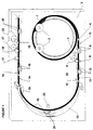
- FIG. 1 A coil of steel rule material 1, nominally but not limited to 300 feet in length, is hanging freely on two flanged rollers 2 rotatably mounted on a suitable baseplate 3.
- the rule unwinding downward passes under roller 4 and thence over roller 5 which relieves the coiling stress and directs the rule along a horizontal path. It then passes through an auxiliary feed mechanism including a pair of edge guide rollers 6, a sensor 7, an auxiliary motorized feed roller 8 with an associated spring loaded pressure roller 9 and a second pair of edge guide rollers 10.
- the edge guide rollers restrain the rule in two dimensions but permit it to move freely in substantially a straight line in the third dimension thereby enabling the feed roller to move the rule forward or backward readily as required.
- the edge guide rollers engage the rule with a V-shaped groove shaped in such a manner that it does not touch the sharp edge of the rule which might otherwise suffer damage.
- the rule then passes through a semi-circular buffer chamber including outer stress relief roller 11, inner stress relief roller 12, semi-circular retaining wall 13, inner stress relief roller 14 and outer stress relief roller 15 following which it is traveling again along a horizontal path above the previous path and in the opposite direction.
- This section is similar to the auxiliary feed mechanism but differs in several important respects.
- the feed drive on the other hand is merely a slave to the main drive to relieve it of as much friction and inertia load as possible particularly that of the supply coil.
- the main drive motor preferably a digital stepper or digital servo, is a high performance motor with good angular resolution and ample power to drive the rule without slippage. Such motors are well known in the trade.
- a highly accurate motion measuring device preferably a high resolution rotary digital encoder 21 driven by measuring roller 18.
- the encoder senses the actual motion of the rule independently of slippage of the drive roller or other factors external to the measuring system.
- the auxiliary feed motor preferably a digitally controlled stepper or servo, in contrast to the main drive motor, requires sufficient power to handle the load of the coil but only with nominal accuracy.
- the motion of the main drive is dictated by the control computer to meet the requirements of some specific processing cycle. In general the motion will be intermittent and both forward & backward but always a net amount forward.
- the feed drive in the meantime is either stationary or moving forward at a slower velocity. These motions cause the rule to pull away from the retaining wall 13 and assume the shape of a free loop 19 restrained only by stress relief rollers 11, 12, 14 and 15. When this loop reaches a specified minimum size it is detected by sensor 23 causing the auxiliary feed motor to advance the rule by a selected amount to enlarge the loop.
- the reaction of the feed motor can be programmed in various ways by anyone familiar with the art but the net result is to maintain a loop size always larger than the minimum but never large enough to contact retaining wall 13.
- Retaining wall 13 is functional only during the initial loading of the coil of rule as a means of guiding the rule automatically through this part of the device and as a protective shield.
- an operator places the coil on flanged rollers 2 and inserts the free end of the rule under roller 4, over roller 5, through the grooves of edge guide rollers 6 and against feed roller 9.
- the auxiliary feed motor becomes energized when the rule is detected by sensor 7 advancing the rule around retaining wall 13.
- the lateral motion of the rule tends to be unstable as it moves around retaining wall 13.
- Sloping side guides 24 located near the midpoint of retaining wall 13 restore the rule to a central location as the leading end passes by and similar sloping side guides 25 bring the rule to an approximate center line enabling it to enter the V-grooves of edge guide rollers 16.
- the main drive motor is alerted when the rule reaches sensor 17 and activated when the measuring encoder detects rule motion. After a brief transition sequence the feed motor stops and the drive motor advances a nominal amount to form free loop 19.
- Sensor 7 also serves as a warning that the coil is exhausted and only a few feet of rule are available.
- sensor 17 detects the end of the rule and shuts down the main drive.
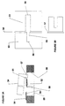
- the second section of the machine is devoted to cutting notches in the rule and to cutting the rule to an accurate length. Its operation can best be understood by reference to Fig 2. Notches are cut out of the rule at selected locations prior to bending. Cutting to length, however, is the final operation to be performed. The rule must first be moved forward or backward to position the desired end point at the cutter. Oftentimes, the cut may be close to the final bend. These conditions dictate that the outlet side of the cutter which is adjacent to the bender should be as open as possible to avoid interference with rule sections bent into complex two-dimensional shapes. The cutter must be narrow and shallow. As a result of this requirement a shearing device as opposed to a punch is the preferred embodiment of this invention.
- a female die 31 is mounted on a rigid base 32 which in turn is mounted on the carriage of slide 33 movable transversely relative to the rule by motor 48 in order to select the notching or cutting operation.
- a mating punch 34 is attached to the lower surface of arm 35 rotatable round bearing 36 on base 32.
- a second arm 37 rotatable around bearing 38 also located on base 32 is coupled to arm 35 by a link 39.
- This double lever arrangement provides a substantial mechanical advantage to reduce the force applied at the outer end of arm 37 to operate the shear while still retaining a satisfactory shear angle.
- the nut 41 of ball screw 42 is pivotally connected to the end of arm 37.
- the supporting bearing 43 for ball screw 42 is mounted on plate 44 pivotally attached to base 32.
- the shear is activated by motor 45, preferably a digital stepper or digital servo, coupled to ball screw 42 by a timing belt and pulleys 46 selected to reduce the motor torque requirement still further.
- motor 45 preferably a digital stepper or digital servo
- This combination of levers, ballscrew and pulleys reduces the torque to a level easily supplied by a small stepper.
- the cavity of die 31 (shown in cross section in Fig. 3A) has an upper level 50 and a lower level 51 with a sloping region 58 at the boundary matching the slope of the cutting edge of rule 52 shown in the cutoff position thereby supporting it firmly along the cutting edge.
- die cavity 53 also slopes outward as well as downward at the boundary region in order to achieve a cutoff with a mitered edge 57 matching the cross-sectional shape of the rule and permitting the cut end to abut the side of another piece of rule, to form a T-shaped pattern, without a gap in the cutting pattern.
- mitered means a projection of one edge of the rule as opposed to an angular cut across the full width.
- the lower level 51 of cavity 53 extends a short distance beyond the rule so no cutting takes place at end 56 of the cavity.
- a protruding tab 57 of punch 34 extends into this section of cavity 53 at all times thereby providing a guide for the punch as it descends.
- Slide 33 shown in Fig. 2 is preferably driven by a digital stepper motor or digital servo motor 48 in order to move the shearing mechanism to any location specified by the system controller.
- This feature enables the cutting operation to be performed away from the sloping region of the cavity producing a straight cut rather than a mitered cut.
- the controlled motion also enables the depth of the notch to be adjusted to any selected value.
- the width of the notch can be varied from a minimum dictated by the width of the cavity 53 to any larger value by multiple notching operations with a suitable movement of either the rule or the die. All of the above is accomplished by computer control only, not requiring any mechanical adjustments.
- Fig 4A shows the situation before the first bend.
- Rule 101 passes through a clamping device comprised of a stationary bar 103 adjacent to a rigid support 104 and a moveable bar 105 driven by an actuator 106, preferably an air cylinder.
- actuator 106 When actuator 106 is energized it forces moveable bar 105 against rule 101 clamping it firmly against stationary bar 103.
- actuator 106 When actuator 106 is released rule 101 can be moved freely between bars 103 and 105 by the main drive assembly of the feed mechanism.
- a bending tool 108 extending across the full width of rule 101 is rotatably mounted with its axis of rotation substantially coincident with the exit aperture 109 of the clamp mechanism.
- Bending tool 108 preferably in the form of a rod of some suitable shape, is mounted parallel to, but a nominal short distance away from exit aperture 109 enabling it to be rotated along the arc 110 pressing against rule 101 and deforming it by a precalculated amount to position 111 shown in Fig. 4B. Bending tool 108 is then rotated in reverse to its former position whereby rule 101 springs back slightly from position 111 to position 112 illustrated in Fig. 4C. Actuator 106 is then released enabling rule 101 to be moved forward to position 113 shown in Fig. 4D. If the sequence of steps illustrated by Figs. 4A to 4D are repeated several times rule 101 has the shape shown in Fig. 4E including a series of small bends each separated by a nominal distance. This shape can be made to approximate a circle of arbitrary radius within any specified tolerance by proper selection of the angle of each bend and the distance between them. Furthermore, if the angle and distance parameters are varied from step to step a compound curve of variable radius can be formed.
- the bent rule tends to spring back somewhat when the bending tool moves away.
- the amount of spring back depends on the characteristics of the rule material, the angle of bend, and the dimensions of the bending mechanism.
- An overbending procedure can be used to compensate for most of the spring back.
- a table of data listing the measured spring back for all angles, materials, and tools is preferably prepared in advance and used for this purpose. This procedure reduces the spring back error but does not eliminate it completely.
- FIG. 5 A unique feature of this invention is illustrated in Fig. 5.
- actuator 117 When actuator 117 is energized both bending bars 103 and 105 and bending tool 108 are withdrawn and disengaged completely from rule 101. While in the withdrawn position, bending tool 108 can be rotated without encountering rule 101 to a position 118 illustrated in Fig.
- clamp bars 103 and 105 and bending tool 108 are open-ended to enable them to be withdrawn. They receive support from stationary member 104 when they are in the bending position. Note also that stationary member 104 and actuator 106 are located outside of the bending plane so as not to obstruct the bending motions for complex rule shapes.
- Another unique feature of the invention is the use of image analysis procedures to monitor the bending process and provide feedback information to improve its accuracy.
- the feedback principle is well known in the trade and widely used throughout industry. In essence, the procedure involves a careful measurement of the output of some operation, a comparison of that measurement with the desired output and utilization of the error so determined to modify the operation to reduce future errors. When correctly applied, feedback improves performance dramatically.
- Fig. 8A illustrates the preferred optical system of the bender used to obtain an image of the bent rule in the vicinity of the last bend.
- Video camera 160 is mounted with its optic axis 161 parallel to the axis of the bending tool but with mirror 162 interposed for structural convenience. The camera is usually focused on the plane of cutting edge 163 of the rule but it may be focused differently.
- the rule is illuminated from behind in silhouette through an axial hole 164 in the rotatable shaft 165 of the bending mechanism by light source 166. Diffusing screen 167 placed between the light source and hole 164 is preferably used to improve the illumination.
- the dotted rectangle 168 in Fig. 8B represents the field of view of the camera.
- Axial hole 164 appears as a bright background within which a section of rule 169 at the exit of clamp 170 appears as a dark stripe of high contrast.
- the high contrast image enhances the extraction of useful information by the image processing procedure.
- the boundaries of the image are the edges of the body of rule not the cutting edge 163 which may have a slightly different shape especially on sharp bends.
- the body shape is precisely the information required since it must be inserted into the corresponding slots in the die base.
- Front illumination by ring light 171 or equivalent can also be employed either separately or together with back illumination to illuminate the sloping sides of the rule near cutting edge 163 thereby enabling the precise shape of the cutting edge to be extracted from the image.
- the image obtained by the video camera is digitized and stored within the memory of the control computer.
- This kind of image capture and digitalization is a well-developed technology, currently used in a variety of fields, including image enhancement of X-rays, aerial photographs, and the like. It is also used for edge detection in the manufacturing of integrated circuits.
- the electronic subsystem used for image capture and digitalization in the present invention will be either the FF-2 Feature Finder, produced by Current Technology, Inc., of Durham, New Hampshire, or the IDL-16 frame grabber, produced by Catenary Systems, Inc., of St. Louis, Missouri, together with the Victor Image Processing Library for Windows, V3.0, also produced by Catenary Systems, Inc. These systems provide the resolution and repeatability required for the present invention.
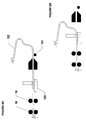
- Fig. 6A shows the essential elements of the complete system including measuring roller 18, main drive roller 19, cutting assembly 120 and bending assembly 121 as they would be disposed after completion of a specific bending pattern 122.
- main drive roller 19 can move the rule backwards to bring pattern 122 close to cutting assembly 120 as illustrated in Fig. 6B enabling the cut to be located close to the last bend in pattern 122. This feature avoids the troublesome procedure of trimming the end of the rule manually as a separate operation.
Landscapes
- Engineering & Computer Science (AREA)
- Mechanical Engineering (AREA)
- Bending Of Plates, Rods, And Pipes (AREA)
Claims (36)
- Verfahren zur Formung von Bandstahl zu einer vorgegebenen Form durch eine Serie von Biegungen, mit den Schritten:(a) Ergreifen des Bandstahls (1, 141) mit einer Greifeinrichtung unter der Steuerung einer Steuereinrichtung, so daß ein Teil des Bandstahles von einer Austrittsseite der Greifeinrichtung hervorsteht,(b) Biegen dieses Abschnittes unter Verwendung einer Biegeeinrichtung unter Steuerung der Steuereinrichtung um einen Betrag, der durch die Steuereinrichtung (147) berechnet wurde, um, unter Berücksichtigung von zumindest der Rückfederung, eine Biegung bis zu einem gewünschten Grad an der ergriffenen Position zu erzeugen, wo der Bandstahl von der Austrittsseite hervorsteht,(c) Bestimmen eines tatsächlichen Betrages der Biegung unter Verwendung der Steuereinrichtung (147), durch optische Analyse eines Profils des Bandstahles an der Biegung,(d) Freigeben des Bandstahles aus der Greifeinrichtung,(e) Vorbewegen des Bandstahles,(f) erneutes Ergreifen des Bandstahles mit der Greifeinrichtung und(g) Biegen des Abschnittes unter Verwendung der Abbiegeeinrichtung und unter Steuerung der Steuereinrichtung um einen weiteren Betrag, der durch die Steuereinrichtung berechnet wurde, um, zumindest unter Berücksichtigung der Rückfederung und einer berechneten Abweichung zwischen dem gewünschten Betrag und dem tatsächlichen Betrag, eine nächste Biegung zu einem als nächstes gewünschten Betrag an einer als nächstes ergriffenen Position zu erzeugen, wo der Bandstahl nach dem Vorbewegen und erneuten Ergreifen aus der Austrittsseite hervorsteht.
- Verfahren nach Anspruch 1, welches weiterhin vor dem Schritt des Ergreifens die Schritte aufweist:Laden einer Spule aus dem Bandstahl auf einen Zuführmechanismus, undZuführen des Bandstahles unter Verwendung des Zuführmechanismus (6, 7, 8, 9, 10, 142) unter der Steuerung der Steuereinrichtung von der Spule zu der Greifeinrichtung.
- Verfahren nach Anspruch 1, welches weiterhin den Schritt aufweist, daß vor dem Schritt des Greifens Elastizitätsdaten, welche den Bandstahl (1, 141) betreffen, in die Steuereinrichtung (147) eingegeber werden, wobei die Steuereinrichtung (147) den Betrag und den nächsten Betrag zumindest teilweise auf Basis der eingegebenen Elastizitätsdaten berechnet.
- Verfahren nach Anspruch 1, welches weiterhin den Schritt aufweist, daß vor dem Schritt des Greifens Forminformationen, welche die vorbestimmte Form betreffen, in die Steuereinrichtung (147) eingegeben werden, wobei die Steuereinrichtung den Betrag und den nächsten Betrag zumindest teilweise auf Basis der eingegebenen Forminformation berechnet.
- Verfahren nach Anspruch 1, welches weiterhin einen Schritt (h) nach dem Schrift (g) des Wiederholens der Schritte (c) bis (g) aufweist, bis der Bandstahl in die vorgegebene Form gebogen worden ist.
- Verfahren nach Anspruch 5, welches weiterhin den Schritt aufweist, daß nach dem Schritt (h) der Bandstahl an einer Position hinter der letzten Biegung abgeschnitten wird.
- Verfahren nach Anspruch 6, wobei der Schneidschritt die Schritte aufweist:Zurückziehen der Biegeeinrichtung und der Greifeinrichtung aus einem Laufweg des Bandstahles, undZurückziehen des Bandstahles bis zur Lokalisierung einer Position an einem Schneidpunkt eines Schneidgerätes (145), an welcher er geschnitten werden soll, und zwar bezüglich einer Richtung der Vorbewegung des Bandstahles stromaufwärts von der Biegeeinrichtung und der Greifeinrichtung.
- Verfahren nach Anspruch 7, welches weiterhin den Schritt aufweist, daß vor dem Schritt des Greifens der Bandstahl unter Verwendung des Schneidgerätes (145) unter der Steuerung der Steuereinrichtung (147) eingekerbt wird.
- Verfahren zur Herstellung von Bandstahlmatrizen bzw. -Schneideisen, bei welchem ein Stahlstreifen durch eine Streifenzuführeinrichtung in eine Maschine zugeführt wird, deren Betrieb in der folgenden Reihenfolge aufweist:(a) Eingeben von Elastizitätsinformation, welche den verwendeten Bandstahl beschreibt in eine Berechnung- und Steuereinheit,(b) Eingeben von Information, welche die gewünschte, herzustellende Form wiedergibt, in die Berechnungs- und Steuereinheit,(c) Berechnen der Stelle der nächsten herzustellenden Biegung, des Winkels der nächsten Biegung und der Richtung der nächsten Biegung in der Berechnungs- und Steuereinheit durch Verwendung eines Programmes, welches bei seinen Berechnungen die Elastizitätsinformation des Stahles und die Forminformation berücksichtigt,(d) Vorbewegen des Stahlstreifens durch eine Antriebseinrichtung (16, 18, 19) durch eine Umsetzereinrichtung (21) für lineare Verschiebung, welche ein Linearverschiebungsmeßsignal bereitstellt, das exakt einen Punkt auf dem Stahlstreifen während des Durchlaufes des Stahlstreifens lokalisiert,(e) festes Ergreifen des Stahlstreifens durch eine Greifeinrichtung, die eine Eingangsseite hat, wo der Stahlstreifen in die Greifeinrichtung eintritt, und eine Ausgangsseite hat, wo der Stahlstreifen aus der Greifeinrichtung austritt, wobei der Stahlstreifen an der nächsten Biegestelle ergriffen wird,(f) Biegen des Stahlstreifens durch eine Biegeeinrichtung (108) an der Ausgangsseite der Greifeinrichtung um den Betrag und in der Richtung, welche durch die Berechnungs- und Steuereinheit berechnet wurde,(g) Betrachten des Bandstahles auf der Ausgangsseite der Greifeinrichtung unter Verwendung optischer Meßeinrichtung, um dadurch ein elektrisches Signal zu erzeugen, welches die Form des Bandstahles repräsentiert,(h) Zuführen des elektrischen Signales zurück zu der Berechnungs- und Steuereinheit,(i) Berechnen der Position, der Verschiebung und der Richtung der nächsten herzustellenden Biegung in der Berechnungs- und Steuereinheit, unter Berücksichtigung des elektrischen Signales, der Information über die Stahlelastizität und der Information über die Form,(j) Wiederholen des Vorganges unter (d) dieses Anspruchs, bis die Matrize bzw das Schneideisen vollständig geformt worden ist,(k) Zurückziehen der Biegeeinrichtung (108) und der Greifeinrichtung von dem Bandstahl,(m) Bewegen des Bandstahles zu der Schneidstelle, und(l) Abtrennen des Bandstahles durch eine Matrizenschneideinrichtung an der letzten Position, welche durch die Berechnungs- und Steuereinheit berechnet wurde.
- Verfahren nach Anspruch 9, welches weiterhin in der folgenden Reihenfolge aufweist:(a) Zuführen des Bandstahles durch eine Kerbeinrichtung während des Matrizenformungsvorganges,(b) Kontrollieren der Kerb- und Schneideinrichtungen mit Hilfe der Berechnungs- und Steuereinheit und(c) Abtrennen der Matrize/des Schneideisens zumindest in der letzten von der Berechnungs- und Steuereinheit berechneten Position.
- Verfahren nach Anspruch 10, welches weiterhin das kontrollierte Bewegen des Stahlstreifens in seiner Längsrichtung aufweist, wobei die Breite der erzeugten Kerbe durch mehrere einander überlappende Kerbungsvorgänge variiert wird.
- Verfahren nach Anspruch 10, welches weiterhin das kontrollierte Bewegen der Kerb- und Schneideinrichtung in einer Richtung senkrecht zur Längsachse des Stahlstreifens, sowie das Einkerben des Stahlstreifens aufweist, wobei die Tiefe der Kerbe variiert wird.
- Verfahren nach Anspruch 9, welches weiterhin das Umsetzen der Position mit Hilfe einer an einem Schaft bzw. an einer Welle eines digitalen Drehencoders angebracht ist.
- Verfahren nach Anspruch 9, welches weiterhin das Greifen mit Hilfe von Klauen aufweist, die mechanisch um den Stahlstreifen geschlossen werden, um den Stahlstreifen zu halten, wobei die Klauen verjüngt zulaufen, um Biegungen über 130° hinaus zu ermöglichen.
- Verfahren nach Anspruch 14, welches weiterhin den Schritt des Biegens mit Hilfe eines Dornes aufweist, welcher durch eine Domtreibereinrichtung angetrieben wird und wobei der Dorn zurückgezogen, dann konzentrisch um eine Achse in der Nähe des Ausgangsendes der Greifeinrichtung gedreht und dann erneut eingesetzt wird, so daß der Dorn auf einer der Seiten des Bandmetalls angeordnet sein kann.
- Verfahren nach Anspruch 15, wobei die Greif- und Biegeeinrichtung aus der Nähe zu dem Bandstahl weggenommen werden kann, so daß die Schneideinrichtung ohne Störung durch die Greif- und Biegeeinrichtung angewendet werden kann.
- Verfahren nach Anspruch 14, welches weiterhin das Biegen mit Hilfe eines Dornes aufweist, der durch eine Dorntreibereinrichtung angetrieben wird, und wobei der Dorn zurückgezogen, dann exzentrisch um eine Achse in der Nähe des Ausgangsendes der Greifeinrichtung gedreht und dann erneut eingesetzt wird, so daß der Dorn auf beiden Seiten des Bandmetalles angeordnet sein kann.
- Verfahren nach Anspruch 17, wobei die Greif- und Biegeeinrichtung aus der Nähe des Bandstahles weggezogen werden kann, so daß die Schneideinrichtung ohne Störung durch die Greif- und Biegeeinrichtung angewendet werden kann.
- Verfahren nach Anspruch 9, wobei die optische Einrichtung eine Videosensoreinrichtung aufweist.
- Vorrichtung zum Formen von Bandstahl zu einer vorbestimmten Form durch eine Reihe von Biegungen, miteiner Steuereinrichtung für die Steuerung des Betriebes der Vorrichtung,einer Greifeinrichtung für das Greifen des Bandstahles unter Steuerung der Steuerungseinrichtung, so daß ein Teil des Bandstahles von einer Ausgangsseite der Greifeinrichtung hervorsteht,einer Einrichtung für das Ablenken bzw. Biegen des Abschnittes um einen berechneten Betrag unter der Steuerung der Steuereinrichtung, undeiner optischen Einrichtung, die so angeordnet ist, daß sie den Abschnitt für das Herstellen sieht und der Steuereinrichtung ein erstes Signal zuführt, welches eine aktuell stattfindende Biegung in dern Bandstahl anzeigt,
wobei die Steuereinrichtung auf das erste Signal anspricht und den berechneten Betrag nach einer ersten Biegung zumindest teilweise auf der Basis als Abweichung zwischen einem gewünschten Beträg einer unmittelbar vorangehenden Biegung und einem tatsächlichen Betrag einer unmittelbar vorangehenden Biegung berechnet wie es durch das erste Signal angezelgt wird. - Vorrichtung nach Anspruch 20, welche weiterhin aufweist:einen Zuführmechanismus (6, 7, 8, 9, 10, 142), unter der Steuerung der Steuereinrichtung, für die Zufuhr von Bandstahl von einer Spule des Bandstahles zu der Greifeinrichtung.
- Vorrichtung nach Anspruch 20, welche weiterhin eine Einrichtung aufweist für das Eingeben von Elastizitätsdaten, welche den Bandstahl betreffen, in die Steuereinrichtung, wobei die Steuereinrichtung jen berechneten Betrag zumindest teilweise auf Basis der eingegebenen Elastizitätsdaten berechnet.
- Vorrichtung nach Anspruch 20, welche weiterhin Einrichtungen aufweist für das Eingeben von Forminformationen, welche die vorbestimmte Form betreffen, in die Steuereinrichtung, wobei die Steuereinrichtung den berechneten Betrag zumindest teilweise auf Basis der eingegebenen Forminformationen berechnet.
- Vorrichtung nach Anspruch 20, welche weiterhin eine Schneideinrichtung unter der Steuerung der Steuereinrichtung aufweist und welche bezüglich einer Vorbewegung des Bandstahles stromaufwärts von der Biegeeinrichtung und der Greifeinrichtung angeordnet sind, um den Bandstahl an einer Stelle hinter einer letzten Biegung abzutrennen.
- Vorrichtung nach Anspruch 20, welche weiterhin aufweist:eine Einrichtung zum Zurückziehen der Um- bzw. Abbiegeeinrichtung und der Greifeinrichtung von einem Bewegungsweg des Bandstahles, undeine Einrichtung zum Zurückziehen des Bandstahles in eine Position, in welcher er abgetrennt werden soll.
- Vorrichtung nach Anspruch 24, wobei die Schneideinrichtung auch für das Einkerben des Bandstahles unter Steuerung durch die Steuereinrichtung vorgesehen ist.
- Vorrichtung für das Biegen von Bandstahl, wobei das Bandstahlvorratsmaterial als eine Materialwicklung bzw. ein Materialrad vorgesehen ist, mit:(a) einer Ladeeinrichtung (142), um einen Vorschub für das Bandstahlvorratsmaterial bereitzustellen,(b) einer Treibereinrichtung (144) für das Vorwärtsbewegen des Bandstahles durch die Vorrichtung,(c) einer Encodereinrichtung für lineare Verschiebung, welche ein Signal bereitstellt, das exakt einen Funkt auf dem Bandstahl lokalisiert, und zwar während des gesamten Durchlaufs,(d) einem programmierbaren Berechnungs- und Steuersystem (147), um eine Gesamtsteuerung und Synchronisation des Betriebes der Vorrichtung bereitzustellen,(e) einer Einrichtung für das Eingeben von Elastizitätsinformation, welche beschreibt, wie der Bandstahl in der Berechnungs- und Steuereinheit verwendet wird,(f) einer Einrichtung für das Eingeben von Information, welche die herzustellende, gewünschte Form wiedergibt, in die Berechnungs- und Steuereinheit,(g) einem Programm für die Steuerung des Berechnungs- und Steuersystems.(h) einer Greifeinrichtung (103, 104, 105, 106), um den Bandstahl fest zu ergreifen, mit einer Eingangsseite und einer Ausgangsseite, wodurch der Bandstahl ergriffen wird,(i) einer Biegeeinrichtung (108) für das Biegen des Bandstahles an der Ausgangsseite der Greifeinrichtung,(j) einer optischen Meß- und Wandlereinrichtung (160, 162, 165, 167) für das Betrachten des Bandstahles auf der Ausgangsseite der Greifeinrichtung, und für das Erzeugen eines elektrischen Signales, welches die Form des Bandstahles repräsentiert,(k) einer Einrichtung für das Zuführen des elektrischen Signales zurück zu der Berechnungs- und Steuereinheit, und(l) einer Einrichtung zum Abtrennen des Bandstahles.
- Vorrichtung nach Anspruch 27, wobei die Schneideinrichtung eine Stempelschneideinrichtung (31, 53, 57) aufweist.
- Vorrichtung nach Anspruch 28, welche weiterhin aufweist:(a) eine Kerbeinrichtung und(b) eine programmierbare Berechnungseinrichtung für das Steuern der Kerb- und Schneideinrichtung.
- Vorrichtung nach Anspruch 29, wobei die Kerb- und Schneideinrichtung einen Stempel beinhaltet, wobei die Form der durch den Stempel erzeugten Kerbe von der Verschiebungsposition des Bandstahles an dem Stempel abhängt.
- Vorrichtung nach Anspruch 30, wobei der Stempel einen verjüngt zulaufenden Abschnitt hat, so daß der Bandstahl mit einem Gehrungsende abgetrennt werden kann.
- Vorrichtung nach Anspruch 28, wobei die Encodereinrichtung für lineare Verschiebung aus einer Rolle besteht, die an einer Welle eines digitalen Drehencoders angebracht ist.
- Vorrichtung nach Anspruch 28, wobei die Greifeinrichtung Klauen aufweist, die verjüngt zulaufend sind, um Biegungen zu ermöglichen, die mehr als 130° betragen.
- Vorrichtung nach Anspruch 28, wobei die Biegeeinrichtung in Form eines Dornes (108) vorliegt, der durch eine Dorntreibereinrichtung (115) angetrieben wird, und wobei der Dorn konzentrisch um eins Achse nahe an dem Austrittsende der Greifeinrichtung gedreht wird, so daß der Dorn auf beiden Seiten des Bandmetalls (101) angeordnet werden kann.
- Vorrichtung nach Anspruch 28, welche weiterhin eine Biegeeinrichtung in Form eines Dornes aufweist, der durch eine Dorntreibereinrichtung angetrieben wird, und wobei der Dorn exzentrisch in der Nähe des Austrittsendes der Greifeinrichtung gedreht wird, so daß der Dorn auf beiden Seiten des Bandmetalles angeordnet werden kann.
- Vorrichtung nach Anspruch 28, wobei die optische Einrichtung eine Videoerfassungseinrichtung (160) aufweist.
Applications Claiming Priority (3)
| Application Number | Priority Date | Filing Date | Title |
|---|---|---|---|
| US08/069,614 US5461893A (en) | 1993-05-28 | 1993-05-28 | Method and apparatus for bending steel rule |
| US69614 | 1993-05-28 | ||
| PCT/US1994/006149 WO1994027761A1 (en) | 1993-05-28 | 1994-05-26 | Method and apparatus for bending steel rule |
Publications (3)
| Publication Number | Publication Date |
|---|---|
| EP0706428A1 EP0706428A1 (de) | 1996-04-17 |
| EP0706428A4 EP0706428A4 (de) | 1996-11-20 |
| EP0706428B1 true EP0706428B1 (de) | 2000-03-22 |
Family
ID=22090117
Family Applications (1)
| Application Number | Title | Priority Date | Filing Date |
|---|---|---|---|
| EP94919309A Expired - Lifetime EP0706428B1 (de) | 1993-05-28 | 1994-05-26 | Verfahren und vorrichtung zum biegen von messerband |
Country Status (6)
| Country | Link |
|---|---|
| US (1) | US5461893A (de) |
| EP (1) | EP0706428B1 (de) |
| JP (1) | JPH08510961A (de) |
| AT (1) | ATE190878T1 (de) |
| DE (1) | DE69423618D1 (de) |
| WO (1) | WO1994027761A1 (de) |
Families Citing this family (45)
| Publication number | Priority date | Publication date | Assignee | Title |
|---|---|---|---|---|
| DE69523446T2 (de) * | 1994-03-29 | 2002-06-27 | Komatsu Ltd., Tokio/Tokyo | Automatisches verfahren zum ausrechnen der stösselhubkompensation einer biegepresse |
| JP3478891B2 (ja) * | 1995-01-11 | 2003-12-15 | 末弘 水河 | 帯刃の製造方法 |
| KR0182069B1 (ko) * | 1995-06-22 | 1999-04-01 | 송병준 | 컷팅블레이드의 절곡시스템 |
| US5881591A (en) * | 1996-08-13 | 1999-03-16 | Ondracek; Carl | Automatic channel letter bending machine |
| WO1998017413A2 (en) * | 1996-10-22 | 1998-04-30 | Laser Products, Inc. | Method and apparatus for forming bends in a selected sequence |
| US5836188A (en) * | 1997-04-09 | 1998-11-17 | Pilot Industries, Inc. | Method and apparatus for bending an elongated member to a target angle |
| JPH11347828A (ja) * | 1998-06-03 | 1999-12-21 | Suehiro Mizukawa | 帯刃加工方法 |
| JPH11347827A (ja) * | 1998-06-03 | 1999-12-21 | Suehiro Mizukawa | 帯刃切断具及び帯刃加工装置 |
| EP1264648A1 (de) * | 1998-06-11 | 2002-12-11 | Hong S. Park | Verfahren zum Biegen und Schneiden von Metallband |
| US6324953B1 (en) | 1998-06-11 | 2001-12-04 | Hong Soon Park | Device for forming cutting blade for prints |
| US6367302B1 (en) | 2000-11-13 | 2002-04-09 | Hong Soon Park | Method for bending and cutting metal strip material |
| CH690063A5 (de) * | 1999-02-11 | 2000-04-14 | Arx Ag | Presswerkzeug. |
| US6094960A (en) * | 1999-04-20 | 2000-08-01 | Kane; Kevin Alan | Metal strip bending device |
| CN1515378B (zh) * | 1999-08-27 | 2010-05-05 | 朴洪顺 | 在切割刀片上形成桥口的切桥型模 |
| WO2001021336A1 (en) * | 1999-09-22 | 2001-03-29 | Carl Ondracek | Automatic retainer bending machine for channel letters |
| WO2001064380A1 (en) * | 2000-03-01 | 2001-09-07 | Suehiro Mizukawa | Blade material cutting device |
| US6604395B2 (en) * | 2001-07-23 | 2003-08-12 | St Assembly Test Services Ltd. | Semi-automated probe bender |
| ITMI20020936A1 (it) * | 2002-05-03 | 2003-11-03 | Pro Form S R L | Metodo migliorato di controllo piegatura per un impianto di produzione di fustelle e relativo dispositivo miglirato di controllo piegatura |
| ITUD20020210A1 (it) * | 2002-10-11 | 2004-04-12 | Antonio Codatto | Procedimento e dispositivo per la piegatura di elementi, |
| WO2004071687A1 (en) * | 2003-02-11 | 2004-08-26 | Hong Soon Park | Method and apparatus for automatically correcting bending angle of cutting blade |
| US20050005664A1 (en) * | 2003-07-09 | 2005-01-13 | Wesley Scott | System and method for bending strip material to create cutting dies |
| DE102004048973A1 (de) * | 2004-10-07 | 2006-04-13 | 2B Präzisionstechnik GmbH für Druck und Industrie | Vorrichtung und Verfahren zum Anpassen von Platten für eine exakte Anordnung an einer Plattentrageinrichtung |
| DE112005003504B4 (de) * | 2005-03-14 | 2011-06-09 | Mizukawa, Suehiro, Settsu | Automatische Biegemaschine für einen Bandstahlstanzstempel, sowie Bandstahlstanzstempel |
| US7387009B2 (en) * | 2005-03-24 | 2008-06-17 | Kevin Kane | Automated bending machine |
| US7383709B2 (en) * | 2005-08-04 | 2008-06-10 | Custom Machining Services, Inc. | System and process for crimping a fitting to a fluid conduit |
| WO2007022197A2 (en) * | 2005-08-15 | 2007-02-22 | Nela Ternes Register Group, Inc. | Methods and apparatuses for making lithographic plates |
| WO2007102176A1 (en) | 2006-03-08 | 2007-09-13 | Pro Form S.R.L. | Device and method for bending a metallic strip |
| US20070264107A1 (en) | 2006-04-14 | 2007-11-15 | Mifsud Vincent D | Material transport system for building panel assembly |
| US7441434B2 (en) * | 2006-05-09 | 2008-10-28 | Sds Usa, Inc. | Channel letter machine and method thereof |
| FR2922127B1 (fr) * | 2007-10-15 | 2010-03-05 | Jaubjaub Consulting | Machine a cintrer un profile et outillage de cintrage pour une telle machine |
| NZ564570A (en) * | 2007-12-18 | 2010-02-26 | Scott Technology Ltd | Metal folding apparatus |
| TWI370248B (en) * | 2008-05-02 | 2012-08-11 | Ind Tech Res Inst | Method and system for inspecting characteristics of bended flexible unit |
| JP5452025B2 (ja) * | 2008-05-19 | 2014-03-26 | 株式会社日立製作所 | 羽根、羽根車、ターボ流体機械 |
| ITVR20110046A1 (it) * | 2011-03-07 | 2012-09-08 | Finn Power Italia S R L | Procedimento per effettuare il controllo della forma di un profilato metallico complesso ottenuto mediante una serie successiva di piegature di una lamiera su macchina pannellatrice |
| KR101275140B1 (ko) * | 2011-05-30 | 2013-06-17 | 동원금속 (주) | 차량용 도어 프레임 벤딩장치 및 벤딩방법 |
| US20120323354A1 (en) * | 2011-06-14 | 2012-12-20 | M.I.C. Industries, Inc. | Systems and Methods for Making Panels from Sheet Material Using Adaptive Control |
| US9314831B2 (en) * | 2011-06-24 | 2016-04-19 | Revcor, Inc. | Manufacturing system and methods |
| CN103480710B (zh) * | 2013-10-15 | 2015-04-01 | 山东森德数控机械有限公司 | 卷耳机耳孔成形限位调整机构 |
| CN104690493B (zh) * | 2013-12-04 | 2017-04-12 | 林凤俊 | 一种不锈钢尺的加工方法 |
| CN104201246B (zh) * | 2014-09-11 | 2017-01-11 | 台州浩然机械制造有限公司 | 一种太阳能组件焊带折弯成型下料一体机 |
| WO2016063306A1 (en) * | 2014-10-23 | 2016-04-28 | Byte Line Di Pelissero Alessandro | Combined device for bending and cutting ribbon-shaped elements and method for bending and cutting ribbon-shaped elements trough such device |
| US11027323B2 (en) * | 2016-06-10 | 2021-06-08 | Advanced Orthodontic Solutions | Method and apparatus for auto-calibration of a wire bending machine |
| US10898977B2 (en) * | 2017-02-27 | 2021-01-26 | Seoul Laser Dieboard System Co., Ltd. | Adding cutting stations to bending systems |
| US11219933B2 (en) * | 2017-11-10 | 2022-01-11 | Promau S.R.L. | Apparatus and method for support and controlled advancement of a metal sheet in a bending machine for obtaining cylindrical or truncated cone structures |
| CN113015584A (zh) * | 2018-08-28 | 2021-06-22 | 安大略模具国际公司 | 用于将金属条成形为模具的系统、装置和方法 |
Family Cites Families (18)
| Publication number | Priority date | Publication date | Assignee | Title |
|---|---|---|---|---|
| US3145756A (en) * | 1961-09-19 | 1964-08-25 | Baldwin Lima Hamilton Corp | Numerically controlled tube bending machine |
| US3821525A (en) * | 1972-03-16 | 1974-06-28 | Conrac Corp | Method and apparatus for automatically compensated tube bending |
| US3837198A (en) * | 1973-04-16 | 1974-09-24 | Bendix Corp | Stereoscopic gage and gaging system |
| GB1511558A (en) * | 1975-07-18 | 1978-05-24 | British Steel Corp | Optical roll alignment device |
| US4161110A (en) * | 1977-04-28 | 1979-07-17 | EVG Entwicklungs- und Verwertungs-Gesellschaft mbH. | Automatic control device for a bending machine |
| US4226143A (en) * | 1979-05-14 | 1980-10-07 | Whitecotton Graydon D | Method of making steel rule type piercing and blanking dies |
| US4280350A (en) * | 1979-12-10 | 1981-07-28 | Consolidated Foods Corporation | Wire bending system |
| US4341008A (en) * | 1980-12-29 | 1982-07-27 | Atlas Steel Rule Die, Inc. | Method of registering a steel rule die and counterplate |
| US4397095A (en) * | 1981-04-09 | 1983-08-09 | Atlas Steel Rule Die, Inc. | Registration and transfer locking unit for a steel rule die and accommodating counter plate |
| GB2119299A (en) * | 1982-03-04 | 1983-11-16 | Pa Management Consult | Making cutting tools |
| DE3216053A1 (de) * | 1982-04-29 | 1983-11-03 | Karl Mengele & Söhne Maschinenfabrik und Eisengießerei GmbH & Co, 8870 Günzburg | Optoelektronisches messverfahren und vorrichtung zur durchfuehrung des verfahrens |
| GB8303954D0 (en) * | 1983-02-12 | 1983-03-16 | Pa Management Consult | Bending metal strip |
| IT1201974B (it) * | 1985-07-22 | 1989-02-02 | Giuliano Gallico | Metodo e macchina per la realizzazione di sagomati spaziali |
| CH665364A5 (fr) * | 1985-10-30 | 1988-05-13 | Cybelec Sa | Dispositif pour le controle automatique de l'operation de pliage lors du pliage avec une presse-plieuse. |
| US4947666A (en) * | 1988-09-16 | 1990-08-14 | The Boeing Company | Method and apparatus for bending an elongate workpiece |
| JP2947362B2 (ja) * | 1989-09-07 | 1999-09-13 | 臼井国際産業株式会社 | チューブの曲げ装置 |
| ATE120389T1 (de) * | 1990-09-28 | 1995-04-15 | Promau Srl | Programmierbare blechbiegemaschine. |
| IT1242690B (it) * | 1990-12-17 | 1994-05-17 | Piegatrici Macch Elettr | Macchina piegatrice sagomatrice per profilati e procedimento di piegatura in coda di profilati. |
-
1993
- 1993-05-28 US US08/069,614 patent/US5461893A/en not_active Expired - Fee Related
-
1994
- 1994-05-26 EP EP94919309A patent/EP0706428B1/de not_active Expired - Lifetime
- 1994-05-26 AT AT94919309T patent/ATE190878T1/de not_active IP Right Cessation
- 1994-05-26 DE DE69423618T patent/DE69423618D1/de not_active Expired - Lifetime
- 1994-05-26 JP JP7501054A patent/JPH08510961A/ja active Pending
- 1994-05-26 WO PCT/US1994/006149 patent/WO1994027761A1/en not_active Ceased
Also Published As
| Publication number | Publication date |
|---|---|
| JPH08510961A (ja) | 1996-11-19 |
| WO1994027761A1 (en) | 1994-12-08 |
| ATE190878T1 (de) | 2000-04-15 |
| DE69423618D1 (de) | 2000-04-27 |
| EP0706428A1 (de) | 1996-04-17 |
| EP0706428A4 (de) | 1996-11-20 |
| US5461893A (en) | 1995-10-31 |
Similar Documents
| Publication | Publication Date | Title |
|---|---|---|
| US5461893A (en) | Method and apparatus for bending steel rule | |
| EP0088576B1 (de) | Verfahren und Vorrichtung zum Herstellen von Schnittwerkzeugen | |
| US6167740B1 (en) | Method and apparatus for forming bends in a selected sequence | |
| CA1181673A (en) | Bending press | |
| US5771725A (en) | Method of producing a band blade, a method of bending a strip material, and an apparatus for bending a stip material | |
| US9895739B2 (en) | Apparatus for making border wire | |
| US6003358A (en) | Method and apparatus for forming bends in a selected sequence | |
| JPH0713847Y2 (ja) | プレスブレーキの曲げ角度検出装置 | |
| EP3310520B1 (de) | Verfahren zur durchführung von präzisen laserzuschnitten auf einer bandfolie und vorrichtung zur durchführung des verfahrens | |
| US4658624A (en) | Bending Machines | |
| US6823708B1 (en) | Sheet metal bending system provided with a press brake and a sheet metal support device and a method to prepare its control data and a computer readable storage medium that stores its control data | |
| GB2116086A (en) | Making cutting tools | |
| US5287721A (en) | Apparatus and method for forming curved needles | |
| EP1190789B1 (de) | Vorrichtung zur Herstellung von Schneidmessern | |
| US5147080A (en) | Staple forming and stapling machine | |
| US7387009B2 (en) | Automated bending machine | |
| KR890002733B1 (ko) | 벤딩 프레스 | |
| US5365813A (en) | System for making picture frames | |
| US20070261460A1 (en) | Channel letter machine and method thereof | |
| EP0063041A2 (de) | Verfahren und Vorrichtung zum stufenweisen Biegen | |
| US3644999A (en) | Apparatus for marking one or more lines on a frame section or the like | |
| JP2000225418A (ja) | ロール成形ライン | |
| JPH0688084B2 (ja) | 折曲げ装置 | |
| US20230256493A1 (en) | Channel Letter Return and Trimcap Material Bending Machine | |
| EP1236528B1 (de) | Schneidvorrichtung zur Herstellung von Schneidmessern |
Legal Events
| Date | Code | Title | Description |
|---|---|---|---|
| PUAI | Public reference made under article 153(3) epc to a published international application that has entered the european phase |
Free format text: ORIGINAL CODE: 0009012 |
|
| 17P | Request for examination filed |
Effective date: 19951228 |
|
| AK | Designated contracting states |
Kind code of ref document: A1 Designated state(s): AT BE CH DE DK ES FR GB GR IE IT LI LU MC NL PT SE |
|
| A4 | Supplementary search report drawn up and despatched |
Effective date: 19961003 |
|
| AK | Designated contracting states |
Kind code of ref document: A4 Designated state(s): AT BE CH DE DK ES FR GB GR IE IT LI LU MC NL PT SE |
|
| GRAG | Despatch of communication of intention to grant |
Free format text: ORIGINAL CODE: EPIDOS AGRA |
|
| 17Q | First examination report despatched |
Effective date: 19990507 |
|
| GRAG | Despatch of communication of intention to grant |
Free format text: ORIGINAL CODE: EPIDOS AGRA |
|
| GRAH | Despatch of communication of intention to grant a patent |
Free format text: ORIGINAL CODE: EPIDOS IGRA |
|
| GRAH | Despatch of communication of intention to grant a patent |
Free format text: ORIGINAL CODE: EPIDOS IGRA |
|
| GRAA | (expected) grant |
Free format text: ORIGINAL CODE: 0009210 |
|
| AK | Designated contracting states |
Kind code of ref document: B1 Designated state(s): AT BE CH DE DK ES FR GB GR IE IT LI LU MC NL PT SE |
|
| PG25 | Lapsed in a contracting state [announced via postgrant information from national office to epo] |
Ref country code: SE Free format text: THE PATENT HAS BEEN ANNULLED BY A DECISION OF A NATIONAL AUTHORITY Effective date: 20000322 Ref country code: NL Free format text: LAPSE BECAUSE OF FAILURE TO SUBMIT A TRANSLATION OF THE DESCRIPTION OR TO PAY THE FEE WITHIN THE PRESCRIBED TIME-LIMIT Effective date: 20000322 Ref country code: LI Free format text: LAPSE BECAUSE OF NON-PAYMENT OF DUE FEES Effective date: 20000322 Ref country code: IT Free format text: LAPSE BECAUSE OF FAILURE TO SUBMIT A TRANSLATION OF THE DESCRIPTION OR TO PAY THE FEE WITHIN THE PRESCRIBED TIME-LIMIT;WARNING: LAPSES OF ITALIAN PATENTS WITH EFFECTIVE DATE BEFORE 2007 MAY HAVE OCCURRED AT ANY TIME BEFORE 2007. THE CORRECT EFFECTIVE DATE MAY BE DIFFERENT FROM THE ONE RECORDED. Effective date: 20000322 Ref country code: GR Free format text: LAPSE BECAUSE OF NON-PAYMENT OF DUE FEES Effective date: 20000322 Ref country code: FR Free format text: LAPSE BECAUSE OF FAILURE TO SUBMIT A TRANSLATION OF THE DESCRIPTION OR TO PAY THE FEE WITHIN THE PRESCRIBED TIME-LIMIT Effective date: 20000322 Ref country code: ES Free format text: THE PATENT HAS BEEN ANNULLED BY A DECISION OF A NATIONAL AUTHORITY Effective date: 20000322 Ref country code: CH Free format text: LAPSE BECAUSE OF NON-PAYMENT OF DUE FEES Effective date: 20000322 Ref country code: BE Free format text: LAPSE BECAUSE OF FAILURE TO SUBMIT A TRANSLATION OF THE DESCRIPTION OR TO PAY THE FEE WITHIN THE PRESCRIBED TIME-LIMIT Effective date: 20000322 Ref country code: AT Free format text: LAPSE BECAUSE OF FAILURE TO SUBMIT A TRANSLATION OF THE DESCRIPTION OR TO PAY THE FEE WITHIN THE PRESCRIBED TIME-LIMIT Effective date: 20000322 |
|
| REF | Corresponds to: |
Ref document number: 190878 Country of ref document: AT Date of ref document: 20000415 Kind code of ref document: T |
|
| REG | Reference to a national code |
Ref country code: CH Ref legal event code: EP |
|
| REF | Corresponds to: |
Ref document number: 69423618 Country of ref document: DE Date of ref document: 20000427 |
|
| REG | Reference to a national code |
Ref country code: IE Ref legal event code: FG4D |
|
| PG25 | Lapsed in a contracting state [announced via postgrant information from national office to epo] |
Ref country code: LU Free format text: LAPSE BECAUSE OF NON-PAYMENT OF DUE FEES Effective date: 20000526 Ref country code: IE Free format text: LAPSE BECAUSE OF NON-PAYMENT OF DUE FEES Effective date: 20000526 |
|
| PG25 | Lapsed in a contracting state [announced via postgrant information from national office to epo] |
Ref country code: GB Free format text: LAPSE BECAUSE OF NON-PAYMENT OF DUE FEES Effective date: 20000622 Ref country code: DK Free format text: LAPSE BECAUSE OF FAILURE TO SUBMIT A TRANSLATION OF THE DESCRIPTION OR TO PAY THE FEE WITHIN THE PRESCRIBED TIME-LIMIT Effective date: 20000622 |
|
| PG25 | Lapsed in a contracting state [announced via postgrant information from national office to epo] |
Ref country code: PT Free format text: LAPSE BECAUSE OF FAILURE TO SUBMIT A TRANSLATION OF THE DESCRIPTION OR TO PAY THE FEE WITHIN THE PRESCRIBED TIME-LIMIT Effective date: 20000623 |
|
| PG25 | Lapsed in a contracting state [announced via postgrant information from national office to epo] |
Ref country code: DE Free format text: LAPSE BECAUSE OF FAILURE TO SUBMIT A TRANSLATION OF THE DESCRIPTION OR TO PAY THE FEE WITHIN THE PRESCRIBED TIME-LIMIT Effective date: 20000624 |
|
| EN | Fr: translation not filed | ||
| NLV1 | Nl: lapsed or annulled due to failure to fulfill the requirements of art. 29p and 29m of the patents act | ||
| REG | Reference to a national code |
Ref country code: CH Ref legal event code: PL |
|
| PG25 | Lapsed in a contracting state [announced via postgrant information from national office to epo] |
Ref country code: MC Free format text: LAPSE BECAUSE OF NON-PAYMENT OF DUE FEES Effective date: 20001130 |
|
| PLBE | No opposition filed within time limit |
Free format text: ORIGINAL CODE: 0009261 |
|
| STAA | Information on the status of an ep patent application or granted ep patent |
Free format text: STATUS: NO OPPOSITION FILED WITHIN TIME LIMIT |
|
| GBPC | Gb: european patent ceased through non-payment of renewal fee |
Effective date: 20000622 |
|
| 26N | No opposition filed | ||
| REG | Reference to a national code |
Ref country code: IE Ref legal event code: MM4A |