EP0706465B1 - Ein brems-fluid-verteilungs-kontroll-system und ein verfahren zur kontrolle der verteilung des brems-fluids - Google Patents
Ein brems-fluid-verteilungs-kontroll-system und ein verfahren zur kontrolle der verteilung des brems-fluids Download PDFInfo
- Publication number
- EP0706465B1 EP0706465B1 EP94921470A EP94921470A EP0706465B1 EP 0706465 B1 EP0706465 B1 EP 0706465B1 EP 94921470 A EP94921470 A EP 94921470A EP 94921470 A EP94921470 A EP 94921470A EP 0706465 B1 EP0706465 B1 EP 0706465B1
- Authority
- EP
- European Patent Office
- Prior art keywords
- accumulator
- pump
- fluid
- brake
- brake fluid
- Prior art date
- Legal status (The legal status is an assumption and is not a legal conclusion. Google has not performed a legal analysis and makes no representation as to the accuracy of the status listed.)
- Expired - Lifetime
Links
- 239000012530 fluid Substances 0.000 title claims description 75
- 238000000034 method Methods 0.000 title claims description 17
- 230000003213 activating effect Effects 0.000 claims description 7
- 238000012544 monitoring process Methods 0.000 claims description 5
- 230000008878 coupling Effects 0.000 claims description 4
- 238000010168 coupling process Methods 0.000 claims description 4
- 238000005859 coupling reaction Methods 0.000 claims description 4
- 238000004891 communication Methods 0.000 claims description 3
- 230000000977 initiatory effect Effects 0.000 claims 1
- 230000004913 activation Effects 0.000 description 6
- 230000001276 controlling effect Effects 0.000 description 4
- 230000003247 decreasing effect Effects 0.000 description 2
- 238000005086 pumping Methods 0.000 description 2
- 238000011217 control strategy Methods 0.000 description 1
- 230000000994 depressogenic effect Effects 0.000 description 1
- 230000001105 regulatory effect Effects 0.000 description 1
- 238000007789 sealing Methods 0.000 description 1
Images

Classifications
-
- B—PERFORMING OPERATIONS; TRANSPORTING
- B60—VEHICLES IN GENERAL
- B60T—VEHICLE BRAKE CONTROL SYSTEMS OR PARTS THEREOF; BRAKE CONTROL SYSTEMS OR PARTS THEREOF, IN GENERAL; ARRANGEMENT OF BRAKING ELEMENTS ON VEHICLES IN GENERAL; PORTABLE DEVICES FOR PREVENTING UNWANTED MOVEMENT OF VEHICLES; VEHICLE MODIFICATIONS TO FACILITATE COOLING OF BRAKES
- B60T8/00—Arrangements for adjusting wheel-braking force to meet varying vehicular or ground-surface conditions, e.g. limiting or varying distribution of braking force
- B60T8/32—Arrangements for adjusting wheel-braking force to meet varying vehicular or ground-surface conditions, e.g. limiting or varying distribution of braking force responsive to a speed condition, e.g. acceleration or deceleration
- B60T8/34—Arrangements for adjusting wheel-braking force to meet varying vehicular or ground-surface conditions, e.g. limiting or varying distribution of braking force responsive to a speed condition, e.g. acceleration or deceleration having a fluid pressure regulator responsive to a speed condition
- B60T8/42—Arrangements for adjusting wheel-braking force to meet varying vehicular or ground-surface conditions, e.g. limiting or varying distribution of braking force responsive to a speed condition, e.g. acceleration or deceleration having a fluid pressure regulator responsive to a speed condition having expanding chambers for controlling pressure, i.e. closed systems
- B60T8/4275—Pump-back systems
-
- B—PERFORMING OPERATIONS; TRANSPORTING
- B60—VEHICLES IN GENERAL
- B60T—VEHICLE BRAKE CONTROL SYSTEMS OR PARTS THEREOF; BRAKE CONTROL SYSTEMS OR PARTS THEREOF, IN GENERAL; ARRANGEMENT OF BRAKING ELEMENTS ON VEHICLES IN GENERAL; PORTABLE DEVICES FOR PREVENTING UNWANTED MOVEMENT OF VEHICLES; VEHICLE MODIFICATIONS TO FACILITATE COOLING OF BRAKES
- B60T8/00—Arrangements for adjusting wheel-braking force to meet varying vehicular or ground-surface conditions, e.g. limiting or varying distribution of braking force
- B60T8/32—Arrangements for adjusting wheel-braking force to meet varying vehicular or ground-surface conditions, e.g. limiting or varying distribution of braking force responsive to a speed condition, e.g. acceleration or deceleration
- B60T8/34—Arrangements for adjusting wheel-braking force to meet varying vehicular or ground-surface conditions, e.g. limiting or varying distribution of braking force responsive to a speed condition, e.g. acceleration or deceleration having a fluid pressure regulator responsive to a speed condition
- B60T8/40—Arrangements for adjusting wheel-braking force to meet varying vehicular or ground-surface conditions, e.g. limiting or varying distribution of braking force responsive to a speed condition, e.g. acceleration or deceleration having a fluid pressure regulator responsive to a speed condition comprising an additional fluid circuit including fluid pressurising means for modifying the pressure of the braking fluid, e.g. including wheel driven pumps for detecting a speed condition, or pumps which are controlled by means independent of the braking system
- B60T8/404—Control of the pump unit
- B60T8/4045—Control of the pump unit involving ON/OFF switching
-
- Y—GENERAL TAGGING OF NEW TECHNOLOGICAL DEVELOPMENTS; GENERAL TAGGING OF CROSS-SECTIONAL TECHNOLOGIES SPANNING OVER SEVERAL SECTIONS OF THE IPC; TECHNICAL SUBJECTS COVERED BY FORMER USPC CROSS-REFERENCE ART COLLECTIONS [XRACs] AND DIGESTS
- Y10—TECHNICAL SUBJECTS COVERED BY FORMER USPC
- Y10S—TECHNICAL SUBJECTS COVERED BY FORMER USPC CROSS-REFERENCE ART COLLECTIONS [XRACs] AND DIGESTS
- Y10S303/00—Fluid-pressure and analogous brake systems
- Y10S303/02—Brake control by pressure comparison
- Y10S303/03—Electrical pressure sensor
- Y10S303/04—Pressure signal used in electrical speed controlled braking circuit
-
- Y—GENERAL TAGGING OF NEW TECHNOLOGICAL DEVELOPMENTS; GENERAL TAGGING OF CROSS-SECTIONAL TECHNOLOGIES SPANNING OVER SEVERAL SECTIONS OF THE IPC; TECHNICAL SUBJECTS COVERED BY FORMER USPC CROSS-REFERENCE ART COLLECTIONS [XRACs] AND DIGESTS
- Y10—TECHNICAL SUBJECTS COVERED BY FORMER USPC
- Y10S—TECHNICAL SUBJECTS COVERED BY FORMER USPC CROSS-REFERENCE ART COLLECTIONS [XRACs] AND DIGESTS
- Y10S303/00—Fluid-pressure and analogous brake systems
- Y10S303/11—Accumulator
Definitions
- This invention relates to vehicle braking systems. More specifically, this invention relates to a fluid distribution control system for use with a closed system application of an anti-locking braking system.
- ABS closed antilocking brake systems
- a pressure increase mode is initiated when a vehicle operator applies pressure to a brake pedal in order to initiate a braking action.
- the ABS operates in pressure increase mode while it is desirable to increase the pressure within the system thereby increasing the pressure that the brakes exert against the wheels to cause deceleration of the vehicle.
- the ABS enters a pressure hold mode.
- a constant pressure is maintained within the brake conduits of the system to provide continued deceleration of the vehicle while concomitantly preventing undesirable wheel lock.
- a third mode which typically follows the pressure hold mode, is known as the pressure decrease mode.
- the pressure decrease mode is typically used when no further pressure is desired for forcing the brakes against the wheels or where a decreased pressure within the brake network is desirable.
- the pressure decrease mode includes dumping or removing the brake fluid from the brake network conduits and returning it to the master cylinder. During pressure decrease, the fluid first travels through the conduits into low pressure accumulators where it can be collected in a rapid fashion. A pump is typically employed to remove the fluid from the accumulators and return it to the master cylinder.
- ABS's antilocking brake systems
- EP-A-0 449 320 have included pumps for draining such accumulators that run continuously throughout all three modes discussed above. Such continuous pump operation is unnecessary, and, at times, undesirable.
- the pump that drains the accumulators need only operate during the third mode when pressure is being decreased within the system.
- Continuous pump operation includes several limitations and drawbacks.
- the pumps typically generate noise at levels that can be disturbing and distracting to a vehicle operator.
- continuous pump operation requires additional power consumption from a vehicle power source such as the main battery.
- continuous pump operation potentially introduces excessive wear on the moving parts within the pump and, potentially, other components of the braking system.
- This invention addresses the need for cyclical control of the accumulator draining pump and seeks to overcome the drawbacks and limitations discussed above.
- This invention provides a system for cyclically controlling pump activation during the pressure decrease mode of operation of an antilocking brake system as in claim 1, and a method of controlling the distribution of brake fluid as in claims 10 and 13.
- This invention includes a system for controlling the distribution of hydraulic fluid, and thereby the pressure, within the conduits of a vehicle braking network.
- the system associated with this invention includes an accumulator that is coupled to the brake network conduits and adapted to receive brake fluid in a rapid fashion.
- the accumulator includes sensing means for indicating the amount of brake fluid within the accumulator.
- a pump for draining the accumulator is coupled to the accumulator.
- the inventive system also includes switching means for activating the pump under preselected conditions during a pressure decrease mode such that the pump removes brake fluid from the accumulator and directs that fluid toward the master cylinder within the brake network.
- the accumulator used with the inventive system is a low pressure accumulator.
- the accumulator preferably includes a housing that has two longitudinal ends; one adapted to be coupled to a pump housing and a second defined by an end wall that has an opening within it.
- the sensing means within the accumulator preferably includes an indicator piston that is slidably received within the accumulator housing. Biasing means are provided for biasing the indicator piston toward the first longitudinal end of the housing. The position of the indicator piston within the accumulator housing is indicative of the amount of brake fluid within the accumulator.
- the sensing means of one embodiment preferably includes a switch housing received in the opening in the end wall of the accumulator housing.
- a switch piston having a first axial end in communication with the indicator piston and a second axial end disposed within the switch housing is slidably received within the switch housing.
- a biasing means for biasing the switch piston toward the indicator piston is also provided.
- An electrical contact has a first end disposed within the switch housing and a second end disposed outside of the switch housing and outside of the accumulator housing. The contact second end is adapted to be electrically coupled to an electronic controller within the ABS network.
- a band is preferably disposed on the switch piston such that the band engages the electrical contact when the indicator piston moves axially within the accumulator housing to a preselected position, whereby the pump is activated responsively to movement of the switch piston.
- Another preferred embodiment of this invention includes a fluid level indicating means within the accumulator that produces a pump activation signal that is recognizable by the ABS electronic controller such that the electronic controller activates the pump for a preselected period in order to remove or evacuate the brake fluid from the accumulator during the pressure decrease mode.
- the method of controlling the distribution of brake fluid within the conduits of a vehicle brake network associated with this invention includes three basic steps. First, the accumulator adapted to receive brake fluid from the brake system conduits in a rapid fashion receives brake fluid is provided. Second, whether the amount of brake fluid within the accumulator is at a preselected level indicating that the accumulator should be emptied or drained of brake fluid is determined. Then the pump is selectively activated when the brake fluid within the accumulator reaches the preselected level such that the brake fluid in the accumulator is removed from the accumulator and directed toward a master cylinder within the brake network. Therefore, the pump is activated only for a limited time during a braking application.
- FIG 1 schematically shows selected components of an antilocking brake system (ABS).
- Braking network 10 includes brake pedal 12 which is depressed by a vehicle operator in order to initiate a braking operation when it is desirable to cause deceleration of the wheels and the vehicle. Actuation of the brake pedal causes a plunger (not shown) to move through master cylinder 14 forcing brake fluid from master cylinder 14 into front and rear brake conduits 16 and 18, respectively.
- Brake fluid traveling through front brake conduit 16 effectively causes front wheels 20 to decelerate because the fluid causes front brakes 22 to bear against front wheels 20.
- the fluid travelling through front conduit 16 bears against front brakes 22 after travelling through normally open valves 24.
- brake fluid passes through rear conduit 18 to cause rear wheels 26 to decelerate due to rear brakes 28 bearing against rear wheels 26 as the fluid builds up within the conduit travelling through normally open valves 30.
- Figure 1 also includes normally closed valves 32 and 34.
- a braking network such as that illustrated in Figure 1 operates under three basic modes.
- a pressure increase mode wherein pressure applied to brake pedal 12 causes brake fluid to flow from the master cylinder through the brake conduits toward brakes 22 and 28.
- normally open valves 24 and 30 are open allowing brake fluid to flow and causing brakes 22 and 28 to bear against wheels 20 and 26, respectively.
- a pressure hold mode is then initiated by the ABS electronic controller (not shown).
- the normally open valves 24 and 30 close; thereby preventing any additional brake fluid from entering the conduits that provide brake fluid and pressure against brakes 22 and 28.
- the pressure hold mode is maintained under conditions, for example, when a vehicle operator is applying an undesirable amount of pressure to brake pedal 12, thereby causing wheels 20 and 26 to lock. Locked wheels can cause vehicle instability and unsafe driving conditions.
- a ABS prevents a driver from applying an undesirable amount of pressure to the brakes 22 and 28 and therefore, promotes safer driving.
- a third mode is then initiated by the ABS electronic controller which shall be referred to herein as the pressure decrease mode.
- the pressure decrease mode normally closed valves 32 and 34 are opened so that brake fluid can pass through the brake conduits into accumulators 36 and 38, respectively.
- Accumulators 36 and 38 function as reservoirs and ore adapted to receive relatively large quantities of brake fluid in a relatively rapid fashion. This procedure is referred to as dumping brake fluid into the accumulators. It is desirable to then redistribute the fluid from the accumulators through the brake conduits into the master cylinder 14.
- switching means 40 is electrically coupled 41 to and activates pump 42.
- Pump 42 evacuates or empties accumulator 36 as it removes the brake fluid from within accumulator 36 and directs that fluid through return conduit 44 toward master cylinder 14.
- switching means 46 activates pump 48 to evacuate accumulator 38 by directing the brake fluid within accumulator 38 through return conduit 50 toward master cylinder 14.
- Switching means 40 and 46 preferably include timing means such that pumps 42 and 48 are activated for a preselected period. In this manner, the inventive system cyclically controls pumps 42 and 48 to remove brake fluid from accumulators 36 and 38, only when necessary.
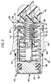
- FIG. 2 illustrates a preferred embodiment of the switching means used with this invention.
- Figure 2 shows accumulator 36 and switching means 40.
- Accumulator 36 includes accumulator housing 60 which is provided with snap ring 62 at a first longitudinal end 63 of accumulator housing 60. Snap ring 62 is provided for coupling accumulator housing 60 to a pump housing (not shown) such that accumulator 36 can be drained by pump 42 when desired.
- Air vent 64 is defined in accumulator housing 60 near a second longitudinal end 65 of accumulator housing 60. Air vent 64 is provided to control the pressure within the accumulator housing as needed.
- Second longitudinal end 65 includes end cap 66 that has a hole 67 defined therein. Hole 67 is provided for receiving switching means 40 within accumulator 36.
- Sealing means 68 is provided between hole 67 and switch housing 70.
- switch housing 70 could be press-fitted into accumulator housing 60.
- Switch housing 70 houses a portion of electrical switch contacts 72. Switch contacts 72 have one end disposed within switch housing 70 and a second end connected to leads 73 that are provided for coupling switching means 40 to the electronic controller (not shown) within the ABS, for example.
- Switch contacts 72 interact with contact band 74 which is disposed on switch piston 76.
- Biasing means 78 is provided to bias switch piston 76 away from leads 73 such that switching means 40 can interact with sensing means 80.
- Sensing means 80 includes indicator piston 82 that moves axially within accumulator housing 60 in response to changing amounts of brake fluid within accumulator 36.
- Biasing means 84 is provided to bias indicator piston 82 towards first longitudinal end 63 of accumulator housing 60.
- Lip seal 86 is provided near one end of indicator piston 82 such that brake fluid will not leak into the portion of accumulator 36 indicated at 88.
- switch piston 78 communicates with indicator piston 82 such that switch piston 76 moves axially through switch housing 70 (from left to right according to the drawing) in response to the movement of indicator piston 82.
- a movement of switch piston 76 causes contact band 74 to come into contact with the first end of switch contacts 72.
- switching means 40 activates pump 42 such that pump 42 can drain the brake fluid from accumulator 36.
- Leads 73 are provided for electrically coupling switching means 40 with pump 42.
- leads 73 are coupled to the ABS electronic controller (not shown).
- the electronic controller initiates a pumping cycle when contact bad 74 engages switch contacts 72, thereby indicating that a preselected capacity level of brake fluid is within accumulator 36.
- the electronic controller preferably includes timing means for regulating the period of pump activation. Such timing means could include a relay switch with a time delay or a hysterisis-type switching device, for example, where a more sophisticated timing control strategy is desired.
- the pump that evacuates the accumulator would be running during all three modes or phases of the antilocking brake operation.
- This invention provides the ability to cyclically control activation of such a pump only when desired or needed; accumulator 36 need only be evacuated during the pressure reducing mode.
- sensing means for indicating the amount of brake fluid within the accumulator include means for producing a pump activation signal that would be recognized by the ABS electronic controller.
- the ABS electronic controller would then interpret the pump activation signal as indicating that the accumulator should be evacuated of brake fluid.
- the ABS electronic controller would then initiate a pumping cycle for a preselected period whereby the accumulator is drained of brake fluid until the level of fluid within the accumulator reached a desired level.
- the electronic controller therefore, serves as the switching means for activating the pump.
- the ABS electronic controller would be provided with appropriate software for monitoring the brake fluid level within the accumulators for cyclically activating the pump that removes brake fluid from the accumulators in the general manner described above.
- the software for the ABS electronic controller would serve as a means for indicating the amount of fluid within the accumulator and for causing the electronic controller to cyclically activate the pump as desired.
- One method includes monitoring such variables as the wheel speed, the slip threshold and driving surface recognition. This data is typically available because it is commonly monitored by an ABS electronic controller. Information regarding the wheel speed, slip threshold and the nature of the driving surface provides the ABS controller with the necessary information to determine whether the amount of brake fluid within the accumulators has reached the preselected capacity level.
- the electronic controller determines when a pressure reducing phase should be initiated relative to the time when wheel lock occurred.
- the electronic controller then activates the pump for a preselected period until the accumulators are properly evacuated of the desired amount of fluid, at which point the pump would then be deactivated.
Landscapes
- Engineering & Computer Science (AREA)
- Physics & Mathematics (AREA)
- Fluid Mechanics (AREA)
- Transportation (AREA)
- Mechanical Engineering (AREA)
- Regulating Braking Force (AREA)
Claims (20)
- Ein System zur Regelung des Drucks in den Leitungen (16, 18, 44, 50) eines KFZ-Bremssystems (10), bestehend aus: einem Sammelbehälter (36, 38), der mit den Leitungen (16, 18, 44, 50) des Bremssystems verbunden ist und Bremsflüssigkeit aufnehmen kann;
sowie einer Pumpe (42, 48), die hydraulisch an diesen Sammelbehälter (36, 38) angeschlossen ist, dadurch gekennzeichnet, daß der Sammelbehälter (36, 38) ein Element (80) umfaßt, das die Bremsflüssigkeitsmenge im Sammelbehälter (36, 38) feststellt; und ein Schaltelement (40, 46), das mit dem Anzeigeelement (80) in Verbindung steht, um die Pumpe (42, 48) unter bestimmten Bedingungen zu aktivieren, wobei die Pumpe (42, 48) Bremsflüssigkeit aus dem Sammelbehälter (36, 38) entfernt. - System gemäß Anspruch 1, wobei die Pumpe (42, 48) mit einem Hauptzylinder (14) verbunden ist, und die aus dem Sammelbehälter (36, 38) entfernte Bremsflüssigkeit in den Hauptzylinder (14) geleitet wird.
- System gemäß Anspruch 1, wobei der Sammelbehälter (36, 38) ein Niederdruck-Sammelbehälter ist.
- System gemäß Anspruch 1, wobei die Sammelvorrichtung (36, 38) ein Gehäuse (60) umfaßt, das über ein erstes in Längsrichtung verlaufendes Ende (63) verfügt, welches mit der Pumpe (42, 48) verbunden werden kann, und ein zweites in Längsrichtung verlaufendes Ende (65), das durch eine Abschlußwand (68) definiert wird, in der sich eine Öffnung befindet.
- System gemäß Anspruch 4, wobei der Fühler (80) folgendes umfaßt:einen Anzeigekolben (82), der gleitend in dem Gehäuse (60) des Sammelbehälters angeordnet ist; undein erstes Vorspannelement (84), das den Anzeigekolben (82) zum ersten in Längsrichtung verlaufenden Ende (63) des Gehäuses (60) vorspannt.
- System gemäß Anspruch 5, wobei das Schaltelement (40, 46) folgendes umfaßt:ein Schaltergehäuse (70), das von der Öffnung (67) in der Abschlußwand (66) aufgenommen wird;einen Schaltkolben (76) mit einem ersten axialen Ende, das mit dem Anzeigekolben (82) in Verbindung steht, und einem zweiten axialen Ende, das in diesem Schaltergehäuse (70) angeordnet ist;ein zweites Vorspannelement (78) zum Vorspannen des Schaltkolbens (76) gegen den Anzeigekolben (82);einen elektrischen Kontakt (72), dessen erstes Ende in dem Schaltergehäuse (70) angeordnet ist, und dessen zweites Ende sich außerhalb des Schaltergehäuses (70) und des Sammelbehältergehäuses (60) befindet, wobei das zweite Ende des Kontakts elektrisch mit einer elektronischen Regelvorrichtung verbunden werden kann;ein Band (74), das auf dem Schaltkolben (76) angeordnet ist, so daß das Band (74) den elektrischen Kontakt (72) ergreift, wenn der Anzeigekolben (82) sich axial im Gehäuse (60) des Sammelbehälters in eine bestimmte Position bewegt, wobei die Pumpe (42, 48) in Abhängigkeit von der Bewegung des Schaltkolbens (76) aktiviert wird.
- System gemäß Anspruch 6, wobei das Schaltelement (40, 46) außerdem ein Zeitschaltelement umfaßt, um einen Zeitraum zu steuern, während dem die Pumpe (42, 48) aktiviert ist.
- System gemäß Anspruch 1, wobei das Schaltelement (40, 46) einen Mikroprozessor umfaßt.
- System gemäß Anspruch 1, wobei das Fühlerelement (80) einen Mikroprozessor umfaßt.
- Methode für die Regelung der Verteilung der Bremsflüssigkeit in den Leitungen (16, 18, 44, 50) eines KFZ-Bremssystems (10), wobei das Bremssystem (10) einen Sammelbehälter (36, 38) einsetzt, der an eine Pumpe (42, 48) angeschlossen ist, und folgende Schritte umfaßt:(A) Aufnahme der Bremsflüssigkeit durch den Sammelbehälter (36, 38);(B) Feststellung, wann die Bremsflüssigkeitsmenge in dem Sammelbehälter (36, 38) einen bestimmten Pegel erreicht hat; und(C) selektive Aktivierung der Pumpe (42, 48), wenn die Bremsflüssigkeit in dem Sammelbehälter (36, 38) den vorher festgelegten Pegel von Schritt (B) erreicht, wobei die Bremsflüssigkeit aus dem Sammelbehälter (36, 38) entfernt wird.
- Methode gemäß Anspruch 10, die einen weiteren Schritt (D) umfaßt, bei dem die Pumpe (42, 48) deaktiviert wird, sobald eine entsprechende Menge an Bremsflüssigkeit aus dem Sammelbehälter (36, 38) entfernt wurde.
- Methode gemäß Anspruch 10, wobei Schritt (C) in Unterschritten ausgeführt wird, d.h. elektrische Verbindung der Pumpe (42, 48) mit einer Stromquelle mit Hilfe eines Schaltelements (40, 46), und Einschränkung des Zeitraums, während dem die Pumpe (42, 48) aktiviert ist, und zwar mit Hilfe eines Schaltelements (40, 46).
- Methode der Regelung der Verteilung von Bremsflüssigkeit und dadurch des Druckes in den Leitungen (16, 18, 44, 50) eines KFZ-ABS-Systems (10), das über eine elektronische Regelvorrichtung verfügt, bestehend aus den folgenden Schritten:(A) schnelles Ablassen von Bremsflüssigkeit aus den Bremsleitungen (16, 18, 44, 50) in ein Reservoir (36, 38);(B) Überwachung des Flüssigkeitsstandes im Reservoir (36, 38) mit Hilfe der elektronischen Regelvorrichtung; und(C) Entfernung der Flüssigkeit aus dem Reservoir (36, 38) sowie Führen der Flüssigkeit zu einem Hauptzylinder (14) in dem Bremssystem (10), wenn die Flüssigkeit den gewünschten Pegel erreicht hat.
- Methode gemäß Anspruch 13, wobei Schritt (C) in Unterschritten ausgeführt wird, d.h. Aktivierung einer Pumpe (42, 48) zur Entfernung der Flüssigkeit aus dem Reservoir (36, 38) und Deaktivierung der Pumpe (42, 48) mit Hilfe der elektronischen Regelvorrichtung, wenn eine bestimmte Menge an Flüssigkeit aus dem Reservoir (36, 38) entfernt wurde.
- Methode gemäß Anspruch 13, wobei Schritt (B) in Unterschritten ausgeführt wird, d.h. Überwachung einer Reihe von Daten, die eine Reihe von Bedingungen definieren, welche den Zustand eines Fahrzeugs beschreiben. Mit Hilfe dieser Daten wird der Flüssigkeitsstand im Reservoir (36, 38) bestimmt.
- Methode gemäß Anspruch 15, wobei die Daten auch Informationen über die Radgeschwindigkeit im Hinblick auf die Zeit umfassen.
- Methode gemäß Anspruch 15, wobei die Daten auch Informationen über die Oberflächenerkennung umfassen.
- Methode gemäß Anspruch 15, wobei die Daten auch Informationen über die Schlupfschwelle umfassen.
- Methode gemäß Anspruch 13, wobei Schritt (B) in Unterschritten ausgeführt wird, d.h. Überwachung einer Reihe von Daten, die eine Reihe von Bedingungen definieren, welche den Zustand des Bremssystems (10) beschreiben. Mit diesen Daten wird die Menge der Bremsflüssigkeit im Reservoir (36, 38) bestimmt.
- Methode gemäß Anspruch 19, wobei diese Daten Informationen über den Ventilzustand umfassen, welche den Status verschiedener Regelventile (24, 30, 32, 34) im Bremssystem (10) umfassen und Signale zur Einleitung bestimmter Betriebsarten, die von der elektronischen Regelvorrichtung erzeugt werden und definieren, ob von dieser ein Druckreduzierungsmodus eingeleitet wurde.
Applications Claiming Priority (3)
| Application Number | Priority Date | Filing Date | Title |
|---|---|---|---|
| US08/089,081 US5388894A (en) | 1993-07-08 | 1993-07-08 | Pump on demand |
| US89081 | 1993-07-08 | ||
| PCT/US1994/007537 WO1995001897A1 (en) | 1993-07-08 | 1994-07-01 | A brake fluid distribution control system and a method of controlling the distribution of brake fluid |
Publications (2)
| Publication Number | Publication Date |
|---|---|
| EP0706465A1 EP0706465A1 (de) | 1996-04-17 |
| EP0706465B1 true EP0706465B1 (de) | 1999-09-22 |
Family
ID=22215581
Family Applications (1)
| Application Number | Title | Priority Date | Filing Date |
|---|---|---|---|
| EP94921470A Expired - Lifetime EP0706465B1 (de) | 1993-07-08 | 1994-07-01 | Ein brems-fluid-verteilungs-kontroll-system und ein verfahren zur kontrolle der verteilung des brems-fluids |
Country Status (5)
| Country | Link |
|---|---|
| US (1) | US5388894A (de) |
| EP (1) | EP0706465B1 (de) |
| JP (1) | JPH08512263A (de) |
| DE (1) | DE69420843T2 (de) |
| WO (1) | WO1995001897A1 (de) |
Families Citing this family (9)
| Publication number | Priority date | Publication date | Assignee | Title |
|---|---|---|---|---|
| DE4412822A1 (de) * | 1994-04-14 | 1995-10-19 | Teves Gmbh Alfred | Hydraulische Bremsanlage mit Schlupfregelung |
| US5522650A (en) * | 1995-02-03 | 1996-06-04 | Kelsey Hayes Company | Method and system for controllably restricting the on time of a vehicular pump in an electro-hydraulic control system |
| DE19602363A1 (de) * | 1996-01-24 | 1997-07-31 | Teves Gmbh Alfred | Bremsdrucksteueranlagen |
| JP3488810B2 (ja) * | 1997-06-12 | 2004-01-19 | 本田技研工業株式会社 | 車両用制動装置 |
| US6276762B1 (en) * | 1999-10-04 | 2001-08-21 | Delphi Technologies, Inc. | Control routine for a hydraulic system pump motor |
| EP1268251B1 (de) * | 2000-03-27 | 2005-11-02 | Continental Teves AG & Co. oHG | Verfahren zur überwachung der notbremsfähigkeit einer elektrohydraulischen bremsanlage |
| US20060196179A1 (en) * | 2005-03-01 | 2006-09-07 | Arun Kesavan | Load-sensing integrated brake and fan hydraulic system |
| JP2007002904A (ja) * | 2005-06-23 | 2007-01-11 | Hitachi Ltd | 電動ブレーキ装置 |
| DE102014207525A1 (de) * | 2014-04-22 | 2015-10-22 | Robert Bosch Gmbh | Verfahren zur Betätigung einer hydraulischen Bremsanlage |
Family Cites Families (23)
| Publication number | Priority date | Publication date | Assignee | Title |
|---|---|---|---|---|
| DE1655383C3 (de) * | 1967-04-08 | 1974-02-28 | Teldix Gmbh, 6900 Heidelberg | Antiblockierregelsystem für eine kolbengesteuerte hydraulische Bremsanlage |
| SE366698B (de) * | 1968-07-08 | 1974-05-06 | Teldix Gmbh | |
| US3659904A (en) * | 1970-06-23 | 1972-05-02 | Fred C Stevens | Non-skid braking system for vehicles |
| JPS59209944A (ja) * | 1983-05-16 | 1984-11-28 | Nissan Motor Co Ltd | アンチスキツド制御装置 |
| US4799048A (en) * | 1984-09-28 | 1989-01-17 | Nippondenso Co., Ltd. | Accumulator |
| DE3532988C2 (de) * | 1985-09-16 | 1994-08-04 | Teves Gmbh Alfred | Elektrohydraulische Schaltvorrichtung |
| DE3603059A1 (de) * | 1986-02-01 | 1987-08-06 | Scheuffele Robert Gmbh Co Kg | Druckschalter |
| JP2650912B2 (ja) * | 1987-06-11 | 1997-09-10 | 曙ブレーキ工業株式会社 | 車両用のアンチロツク装置 |
| JP2677377B2 (ja) * | 1987-08-30 | 1997-11-17 | 株式会社デンソー | ブレーキ装置用アキュムレータの圧力制御装置 |
| JPS6467464A (en) * | 1987-09-04 | 1989-03-14 | Fuji Heavy Ind Ltd | Anti-skid control method for automobile |
| GB8724608D0 (en) * | 1987-10-21 | 1987-11-25 | Lucas Ind Plc | Anti-skid braking systems |
| DE3813172C2 (de) * | 1988-04-20 | 1998-02-12 | Teves Gmbh Alfred | Blockiergeschützte hydraulische Bremsanlage |
| KR920703370A (ko) * | 1989-10-20 | 1992-12-17 | 우. 그라우·페.포르트비히 | 전동유압 제어장치 |
| US5089675A (en) * | 1990-03-29 | 1992-02-18 | Acustar, Inc. | Resistor card calibration retention method and fuel pump switch |
| EP0449320B1 (de) * | 1990-03-30 | 1996-12-11 | Akebono Brake Industry Co., Ltd. | Bremssteuereinheit |
| DE4015866C2 (de) * | 1990-05-17 | 2003-06-12 | Continental Teves Ag & Co Ohg | Schaltungsanordnung für eine blockiergeschützte Bremsanlage |
| DE4016752A1 (de) * | 1990-05-25 | 1991-11-28 | Teves Gmbh Alfred | Bremsdruckregelvorrichtung und verfahren zu ihrer anwendung |
| JPH0466360A (ja) * | 1990-07-06 | 1992-03-02 | Toyota Motor Corp | 蓄圧装置 |
| JP2885903B2 (ja) * | 1990-08-03 | 1999-04-26 | 本田技研工業株式会社 | 車両用流体圧供給装置 |
| JP2936670B2 (ja) * | 1990-08-07 | 1999-08-23 | トヨタ自動車株式会社 | 還流式アンチロック型ブレーキシステム |
| JP2616191B2 (ja) * | 1990-09-17 | 1997-06-04 | トヨタ自動車株式会社 | 還流式アンチロック型ブレーキシステム |
| DE4037142A1 (de) * | 1990-11-22 | 1992-05-27 | Bosch Gmbh Robert | Elektromotorisch betriebene hydropumpe |
| JPH04266561A (ja) * | 1991-02-20 | 1992-09-22 | Jidosha Kiki Co Ltd | アンチスキッドブレーキ制御システムにおけるポンプモータリレーの作動装置 |
-
1993
- 1993-07-08 US US08/089,081 patent/US5388894A/en not_active Expired - Lifetime
-
1994
- 1994-07-01 WO PCT/US1994/007537 patent/WO1995001897A1/en not_active Ceased
- 1994-07-01 DE DE69420843T patent/DE69420843T2/de not_active Expired - Lifetime
- 1994-07-01 JP JP7504119A patent/JPH08512263A/ja not_active Ceased
- 1994-07-01 EP EP94921470A patent/EP0706465B1/de not_active Expired - Lifetime
Also Published As
| Publication number | Publication date |
|---|---|
| JPH08512263A (ja) | 1996-12-24 |
| DE69420843D1 (de) | 1999-10-28 |
| US5388894A (en) | 1995-02-14 |
| WO1995001897A1 (en) | 1995-01-19 |
| EP0706465A1 (de) | 1996-04-17 |
| DE69420843T2 (de) | 2000-03-09 |
Similar Documents
| Publication | Publication Date | Title |
|---|---|---|
| US4826255A (en) | Anti-lock brake system with variable delivery pump controlled in response to detected position of master cylinder piston and method therefor | |
| US5967624A (en) | Process of operating an anti-lock motor vehicle brake system | |
| JP2649935B2 (ja) | 路上走行車用の液圧式多重回路形ブレーキ装置を持ったアンチロック装置 | |
| US4783125A (en) | Slip-controlled hydraulic brake system | |
| JP3620108B2 (ja) | 蓄圧制御装置 | |
| EP0706465B1 (de) | Ein brems-fluid-verteilungs-kontroll-system und ein verfahren zur kontrolle der verteilung des brems-fluids | |
| US4984164A (en) | Anti-lock control method and apparatus for vehicles | |
| US6007165A (en) | Acceleration slip control system for motor vehicle | |
| EP0227332B1 (de) | Blockierverhinderer für Fahrzeuge | |
| US6246946B1 (en) | Automotive brake control system with skid control unit | |
| US5522650A (en) | Method and system for controllably restricting the on time of a vehicular pump in an electro-hydraulic control system | |
| JP4645782B2 (ja) | 車両の液圧ブレーキ装置 | |
| KR19990062747A (ko) | 제동력 배분 제어 방법 | |
| US6290311B1 (en) | Brake system of vehicle for simultaneous execution of driver's braking and automatic behavior control | |
| JPS61102336A (ja) | 車両の制動装置 | |
| JPH04231247A (ja) | ブレーキ圧制御装置 | |
| JP2000223312A (ja) | 車両の制動力制御装置 | |
| US5324103A (en) | Automotive brake control system | |
| US5282675A (en) | Braking anti-lock control for vehicle | |
| US20010013723A1 (en) | Anti-lock brake control device and method | |
| JPH08127331A (ja) | 液圧ブレーキ装置 | |
| US6224168B1 (en) | Fluid pressure generating system for a vehicle and brake fluid pressure control system for a vehicle | |
| US6244670B1 (en) | Method for controlling a hydraulic braking system in open loop | |
| US5178440A (en) | Antiskid brake control method | |
| JPS62122860A (ja) | 車両における車輪のロツク防止方法 |
Legal Events
| Date | Code | Title | Description |
|---|---|---|---|
| PUAI | Public reference made under article 153(3) epc to a published international application that has entered the european phase |
Free format text: ORIGINAL CODE: 0009012 |
|
| 17P | Request for examination filed |
Effective date: 19960208 |
|
| AK | Designated contracting states |
Kind code of ref document: A1 Designated state(s): DE FR GB SE |
|
| 17Q | First examination report despatched |
Effective date: 19960429 |
|
| GRAG | Despatch of communication of intention to grant |
Free format text: ORIGINAL CODE: EPIDOS AGRA |
|
| GRAG | Despatch of communication of intention to grant |
Free format text: ORIGINAL CODE: EPIDOS AGRA |
|
| GRAH | Despatch of communication of intention to grant a patent |
Free format text: ORIGINAL CODE: EPIDOS IGRA |
|
| GRAH | Despatch of communication of intention to grant a patent |
Free format text: ORIGINAL CODE: EPIDOS IGRA |
|
| GRAA | (expected) grant |
Free format text: ORIGINAL CODE: 0009210 |
|
| AK | Designated contracting states |
Kind code of ref document: B1 Designated state(s): DE FR GB SE |
|
| REF | Corresponds to: |
Ref document number: 69420843 Country of ref document: DE Date of ref document: 19991028 |
|
| ET | Fr: translation filed | ||
| PLBE | No opposition filed within time limit |
Free format text: ORIGINAL CODE: 0009261 |
|
| STAA | Information on the status of an ep patent application or granted ep patent |
Free format text: STATUS: NO OPPOSITION FILED WITHIN TIME LIMIT |
|
| 26N | No opposition filed | ||
| REG | Reference to a national code |
Ref country code: GB Ref legal event code: IF02 |
|
| PGFP | Annual fee paid to national office [announced via postgrant information from national office to epo] |
Ref country code: DE Payment date: 20130731 Year of fee payment: 20 Ref country code: SE Payment date: 20130725 Year of fee payment: 20 |
|
| PGFP | Annual fee paid to national office [announced via postgrant information from national office to epo] |
Ref country code: FR Payment date: 20130719 Year of fee payment: 20 Ref country code: GB Payment date: 20130724 Year of fee payment: 20 |
|
| REG | Reference to a national code |
Ref country code: DE Ref legal event code: R071 Ref document number: 69420843 Country of ref document: DE |
|
| REG | Reference to a national code |
Ref country code: GB Ref legal event code: PE20 Expiry date: 20140630 |
|
| PG25 | Lapsed in a contracting state [announced via postgrant information from national office to epo] |
Ref country code: GB Free format text: LAPSE BECAUSE OF EXPIRATION OF PROTECTION Effective date: 20140630 |
|
| REG | Reference to a national code |
Ref country code: SE Ref legal event code: EUG |
|
| PG25 | Lapsed in a contracting state [announced via postgrant information from national office to epo] |
Ref country code: DE Free format text: LAPSE BECAUSE OF EXPIRATION OF PROTECTION Effective date: 20140702 |