EP0706857A1 - Machine de polissage pour plaquettes semi-conductrices - Google Patents
Machine de polissage pour plaquettes semi-conductrices Download PDFInfo
- Publication number
- EP0706857A1 EP0706857A1 EP95307203A EP95307203A EP0706857A1 EP 0706857 A1 EP0706857 A1 EP 0706857A1 EP 95307203 A EP95307203 A EP 95307203A EP 95307203 A EP95307203 A EP 95307203A EP 0706857 A1 EP0706857 A1 EP 0706857A1
- Authority
- EP
- European Patent Office
- Prior art keywords
- fluid
- support
- polishing pad
- pad assembly
- semiconductor wafer
- Prior art date
- Legal status (The legal status is an assumption and is not a legal conclusion. Google has not performed a legal analysis and makes no representation as to the accuracy of the status listed.)
- Granted
Links
- 238000005498 polishing Methods 0.000 title claims abstract description 67
- 239000012530 fluid Substances 0.000 claims abstract description 128
- 239000004065 semiconductor Substances 0.000 claims abstract description 14
- 238000004891 communication Methods 0.000 claims description 7
- 235000012431 wafers Nutrition 0.000 description 25
- 239000000126 substance Substances 0.000 description 6
- 238000005461 lubrication Methods 0.000 description 4
- XLYOFNOQVPJJNP-UHFFFAOYSA-N water Substances O XLYOFNOQVPJJNP-UHFFFAOYSA-N 0.000 description 4
- 230000002706 hydrostatic effect Effects 0.000 description 3
- 239000002002 slurry Substances 0.000 description 3
- 238000005452 bending Methods 0.000 description 2
- 230000000694 effects Effects 0.000 description 2
- 230000002093 peripheral effect Effects 0.000 description 2
- 238000003491 array Methods 0.000 description 1
- 238000011109 contamination Methods 0.000 description 1
- 230000003247 decreasing effect Effects 0.000 description 1
- 230000002708 enhancing effect Effects 0.000 description 1
- 239000007788 liquid Substances 0.000 description 1
- 238000012423 maintenance Methods 0.000 description 1
- 239000000463 material Substances 0.000 description 1
- 238000012986 modification Methods 0.000 description 1
- 230000004048 modification Effects 0.000 description 1
- 238000007517 polishing process Methods 0.000 description 1
- 229910001220 stainless steel Inorganic materials 0.000 description 1
- 239000010935 stainless steel Substances 0.000 description 1
Images



Classifications
-
- B—PERFORMING OPERATIONS; TRANSPORTING
- B24—GRINDING; POLISHING
- B24B—MACHINES, DEVICES, OR PROCESSES FOR GRINDING OR POLISHING; DRESSING OR CONDITIONING OF ABRADING SURFACES; FEEDING OF GRINDING, POLISHING, OR LAPPING AGENTS
- B24B37/00—Lapping machines or devices; Accessories
- B24B37/11—Lapping tools
- B24B37/20—Lapping pads for working plane surfaces
-
- B—PERFORMING OPERATIONS; TRANSPORTING
- B24—GRINDING; POLISHING
- B24B—MACHINES, DEVICES, OR PROCESSES FOR GRINDING OR POLISHING; DRESSING OR CONDITIONING OF ABRADING SURFACES; FEEDING OF GRINDING, POLISHING, OR LAPPING AGENTS
- B24B21/00—Machines or devices using grinding or polishing belts; Accessories therefor
- B24B21/04—Machines or devices using grinding or polishing belts; Accessories therefor for grinding plane surfaces
- B24B21/06—Machines or devices using grinding or polishing belts; Accessories therefor for grinding plane surfaces involving members with limited contact area pressing the belt against the work, e.g. shoes sweeping across the whole area to be ground
Definitions
- This invention relates to chemical mechanical polishing machines for planarizing semi-conductor wafers, and in particular to such machines having improved bearings.
- Chemical mechanical polishing machines for semi-conductor wafers are well known in the art, as described for example in U.S. Patents 5,335,453, 5,329,732, 5,287,663, 5,297,361 and 4,811,522.
- Such mechanical bearings can provide disadvantages in operation. Mechanical bearings can become contaminated with the abrasive slurry used in the polishing process. If mechanical bearings provide point or line support for a polishing pad platen, the possibility of cantilever bending of the platen arises. Bearing vibrations can result in undesirable noise, and bearing adjustment typically requires a mechanical adjustment of the assembly. This adjustment is typically a high-precision, time-consuming adjustment.
- This invention relates to semi-conductor wafer polishing machines of the type comprising at least one polishing pad assembly and at least one wafer holder positioned to hold a semi-conductor wafer against the polishing pad assembly.
- such a wafer polishing machine is provided with a support positioned adjacent the polishing pad assembly.
- At least one of the support and the polishing pad assembly comprises a plurality of fluid bearings that support the polishing pad assembly on the support.
- Each of the fluid bearings comprises a respective fluid supply conduit connectable to a respective source of fluid at a respective pressure and a respective set of fluid pads.
- Each of the fluid pads within a given fluid bearing is in fluid communication with the respective fluid supply conduit.
- the fluid pads are configured to direct fluid from the respective fluid supply conduit to support in part the polishing pad assembly on the support.
- at least some of the sets of fluid pads are arranged in respective concentric rings.
- Figure 1 is a perspective view of a chemical mechanical wafer polishing machine.
- Figure 2 is a perspective view of a belt support assembly included in the polishing machine of Figure 1.
- Figure 3 is a top view of hydrostatic bearings included in the belt support assembly of Figure 2.
- Figure 4 is a perspective view of portions of another chemical mechanical wafer polishing machine.
- Figure 5 is a perspective view of the belt support assembly of the polishing machine of Figure 4.
- Figure 6 is a perspective view at an expanded scale of a portion of the belt support assembly of Figure 5.
- Figure 7 is a top view of the belt support assembly of Figure 5.
- Figure 8 is a top view of another belt support assembly suitable for use in the polishing machine of Figure 4.
- Figure 9 is a cross-sectional view taken along line 9-9 of Figure 8.
- Figure 10 is a cross-sectional view taken along line 10-10 of Figure 9.
- Figure 11 is a side view taken along line 11-11 of Figure 10.
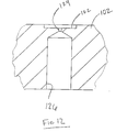
- Figure 12 is an enlarged view of a portion of the belt support assembly of Figure 9.
- Figure 13 is a top view of another belt support assembly.
- Figures 1-3 relate to a chemical mechanical wafer polishing machine 10 that incorporates a wafer holder 12 which holds a wafer W against a polishing pad assembly 14.
- the polishing pad assembly 14 includes a belt 16 which carries on its outer surface one or more polishing pads 18.
- the belt 16 travels over rollers 20 which are driven in rotation to cause the belt to move linearly past the wafer holder 12.
- the belt 16 is supported with respect to movement away from the wafer W by a belt support assembly 22 which is shown more clearly in Figure 2.
- the belt support assembly 22 includes a support 24 which is fixedly mounted in position with respect to the rollers 20. This support 24 defines a hemispherical recess 26 which supports a belt platen 28.
- the belt platen 28 defines a lower hemispherical surface 30 that is received within the recess 26 to form a ball joint.
- the uppermost portion of the platen 28 defines a belt support surface 32.
- the belt 16 may be wetted and the belt support surface 32 may be grooved to prevent the belt 16 from hydro-planing.
- the belt support surface 32 may be formed of a low-friction bearing material.
- FIG. 3 is a top view into the recess 26 with the platen 28 removed. As shown in Figure 3, the recess 26 defines a total of five fluid bearings 34 in this embodiment. One of these fluid bearings 34 is larger than the other four and is positioned centrally. The remaining four fluid bearings 34 are positioned symmetrically around the central fluid bearing.
- Each of the fluid bearings includes a central fluid inlet 36 which is connectable to a source of fluid under pressure and a respective fluid outlet 38 that is annular in shape and extends around the fluid inlet 36. Each fluid outlet 38 is connectable to a drain of fluid at a lower pressure than that of the source.
- the region of the recess 26 between the fluid inlet 36 and the fluid outlet 38 forms a bearing surface 40.
- fluid is pumped from the fluid inlet 36 across the bearing surface 40 to the fluid outlet 38.
- a film of fluid is formed over the bearing surface 40, and it is this film of fluid that supports the hemispherical surface 30 of the platen 28.
- the larger central fluid bearing 34 supports the platen 28 against movement away from the belt 16.
- the four smaller fluid bearings 34 provide self-centering characteristics in order maintain the platen 28 centered in the recess 26.
- the recess 26 and the hemispherical surface 30 are shaped such that the center of rotation 42 of the ball joint formed by the support 24 and the platen 28 is positioned substantially at the front surface of the wafer W that is being polished. In this way, tilting moments on the platen 28 are minimized and any tendency of the ball joint formed by the platen 28 and the support 24 to press the belt 16 with greater force into the leading edge of the wafer W is minimized or eliminated.
- FIGs 4-7 relate to a wafer polishing machine in which the belt 16 is supported by a belt support assembly 60.
- This belt support assembly 60 includes a support 62 which acts as a manifold for pressurized fluid and includes a raised peripheral rim 66 ( Figure 5).
- a plurality of cylindrical tubes 68 are contained within the rim 66, and each of these tubes 68 defines an exposed annular end surface 70.
- the manifold is connected to the interiors of the tubes 68 via fluid inlets 72, and a plurality of fluid outlets 74 are provided as shown in Figure 7.
- Individual ones of the tubes 68 are sealed to the support 62 by seals 78 that allow a controlled amount of movement of the tubes 68.
- the seal 78 can be formed of an elastomeric O-ring which bears against a lower cap of the tube 68, and the fluid inlet 72 can be a hollow fastener that secures the tube 68 to the support 62 and compresses the seal 78.
- interstitial spaces 76 between adjacent tubes 68 allow fluid to flow out of the tubes 68 to the fluid outlets 74.
- the tubes 68 can define an array having a diameter of about eight inches, and 187 tubes can be used, each having an outside diameter of 1/2 inch and an inside diameter of 3/8 inch, and the fluid inlets 72 can be about 0.030 inches in diameter.
- the manifold is connected to a source of fluid such as water at an elevated pressure, and the fluid outlets 74 are connected to a fluid drain at a lower pressure such as atmospheric pressure. Fluid flows into the tubes 68 via the fluid inlet 72, across the end surfaces 70 which act as bearing surfaces, via the interstitial spaces 76 and the fluid outlets 74 to the fluid drain. The fluid flow over the end surfaces 70 provides broad-area support for the belt 16.
- Figures 1-7 are included in co-pending U.S. patent application Serial No. 08/321,085, filed October 11, 1994 (Attorney Docket No. 7103/4). The entirety of this co-pending application is hereby incorporated by reference.
- FIGS 8-12 show another support 100 that can for example be used to support the polishing pad assembly 14 in the wafer polishing machine 10.
- This support 100 includes an upper plate 102 and a lower plate 104 which are held together by fasteners 106.
- the lower plate 104 defines eight fluid supply conduits 108, each having a respective threaded end 110 and a discharge end 112.
- the threaded ends 110 in use are each connected to a separate respective source of pressurized fluid at a separate respective pressure.
- the discharge ends 112 are each in fluid communication with a respective one of eight concentric grooves 114.
- adjacent ones of the concentric grooves 114 are separated by lands 118 which define O-ring receiving grooves 118.
- O-rings 120 are positioned in the grooves 118 to create a seal between the upper and lower plates 102, 104 between adjacent concentric grooves 114.
- the upper plate 102 defines eight circular arrays of fluid pads 122, each array aligned with a respective one of the concentric grooves 114.
- Each fluid pad 122 is connected by means of an orifice 124 and a bore 126 to the respective groove 114.
- the central fluid pad 128 is in fluid communication with the innermost concentric groove 114, as shown in Figures 9 and 10.
- fluid is supplied under respective pressures to the conduits 108 and it flows via the conduits 108, the grooves 104, the bores 126 and the orifices 128 to the fluid pads 122. Pressurized fluid then is directed against the polishing pad assembly and it tends to flow radially outwardly to a drain (not shown) at a lower pressure.
- the support 100 may utilize three different modes of lubrication: hydrostatic fluid lubrication at the outer fluid bearing, localized hydrodynamic fluid lubrication inside the hydrostatic region and mixed fluid film lubrication at the points of asperity contact.
- each of these fluid bearings includes a respective circle of fluid pads 122 aligned with the respective concentric groove 114.
- the innermost fluid bearing includes the central pad 128.
- Each of these fluid bearings operates with a fluid such as water conducted via a respective fluid supply conduit 108 at a respective pressure.
- the pressure of the peripheral fluid bearings can be either increased or decreased with respect to the pressure of the central fluid bearings in order to make the polishing rate more uniform across the surface of the wafer being polished.
- the concentric fluid bearings provide concentric regions of support which can be precisely adjusted by adjusting the pressure in the fluid in the respective conduit 108.
- the fluid pads 122 direct fluid to support the underside of the polishing pad assembly 14.
- the support 100 can be used with a rotating polishing pad assembly rather than one which moves linearly as described above.
- the fluid bearings have been shown on the support, they could be formed on the polishing pad assembly in alternative embodiments.
- the support 60 of Figures 4-7 can be modified to provide multiple regions of support operating at different fluid pressures.
- the fluid inlets 72 can be connected to separate respective manifolds such that the fluid inlets 72 in concentric rings are supplied with fluid at respective pressures.
- the fluid inlets 72 can be connected to manifolds at respective pressures in other spatial patterns if desired.
- the individual fluid pads 122 can be 0.25 inch in diameter by 0.05 inch in depth, and the orifices 124 can be 0.020 inches in diameter.
- the upper and lower plates 102, 104 can be formed of a stainless steel such as type 304, and the fluid bearings on the support 100 can have a maximum diameter comparable to that of the wafer being polished.
- Figure 13 is a top view of a polishing pad support 100' that is in many ways identical to the support 100 described above.
- the upper surface of the upper plate 102' includes drainage features including radial grooves 130' and communicating concentric grooves 132'. All of the grooves 130', 132' are in fluid communication with one another, and the spaces between the grooves 130', 132' and the fluid pads 122' constitute raised lands 134'. Fluid passes from the fluid pads 122' to the grooves 130', 132' over the lands 134'. In this way, drainage of the various fluid bearings is enhanced as the movement of fluid toward the periphery of the upper plate 102' is facilitated by the grooves 130', 132'. In all other respects the support 100' is identical to the support 100 described above.
- the grooves 130' 132' are approximately 0.05 inch in depth and are provided with rounded edges to reduce damage to the overlying polishing pad assembly (not shown).
- the illustrated arrangement provides an asymmetrical arrangement for the grooves 130'. By repositioning the fasteners, it would be possible to achieve a more nearly symmetrical array of grooves 130', which might provide advantages.
- the grooves 130', 132' could also be adapted for use with the embodiment of Figures 4-7.
- the fluid bearings described above provide a number of important advantages.
- the constant flow of fluid out of the bearing allows for no slurry contamination.
- These fluid bearings provide excellent stiffness and wide-area support, thereby reducing or eliminating cantilever bending of the platen.
- These bearings are nearly frictionless and vibrationless, and therefore they provide the further advantage of reduced noise.
- These bearings are extremely stable and robust, and they can readily be adjusted merely by controlling fluid pressure. This lends itself to simple, closed-loop feedback control systems.
- the preferred bearing fluid is liquid water, which is slurry compatible. These bearings are extremely reliable with hardly any maintenance or wear.
Landscapes
- Engineering & Computer Science (AREA)
- Mechanical Engineering (AREA)
- Mechanical Treatment Of Semiconductor (AREA)
- Finish Polishing, Edge Sharpening, And Grinding By Specific Grinding Devices (AREA)
Applications Claiming Priority (4)
| Application Number | Priority Date | Filing Date | Title |
|---|---|---|---|
| US321085 | 1994-10-11 | ||
| US08/321,085 US5593344A (en) | 1994-10-11 | 1994-10-11 | Wafer polishing machine with fluid bearings and drive systems |
| US08/333,463 US5558568A (en) | 1994-10-11 | 1994-11-02 | Wafer polishing machine with fluid bearings |
| US333463 | 1994-11-02 |
Publications (2)
| Publication Number | Publication Date |
|---|---|
| EP0706857A1 true EP0706857A1 (fr) | 1996-04-17 |
| EP0706857B1 EP0706857B1 (fr) | 1999-07-14 |
Family
ID=26982813
Family Applications (1)
| Application Number | Title | Priority Date | Filing Date |
|---|---|---|---|
| EP95307203A Expired - Lifetime EP0706857B1 (fr) | 1994-10-11 | 1995-10-11 | Machine de polissage pour plaquettes semi-conductrices |
Country Status (4)
| Country | Link |
|---|---|
| EP (1) | EP0706857B1 (fr) |
| JP (1) | JPH08195363A (fr) |
| AT (1) | ATE182103T1 (fr) |
| DE (1) | DE69510745T2 (fr) |
Cited By (21)
| Publication number | Priority date | Publication date | Assignee | Title |
|---|---|---|---|---|
| EP0841571A2 (fr) * | 1996-11-08 | 1998-05-13 | W.L. GORE & ASSOCIATES, INC. | Montage et substrat de base pour prévieillissement de plaquettes de circuits intégrés |
| WO1999050025A1 (fr) * | 1998-03-31 | 1999-10-07 | Lam Research Corporation | Appareil et procede de mesure d'epaisseur de film integres dans une unite de charge/decharge de plaquettes |
| EP0893203A3 (fr) * | 1997-05-28 | 2000-01-12 | LAM Research Corporation | Procédé et dispositif pour la détermination in-situ du point d'arrêt et pour l'optimisation d'un procédé de polissage à polisseur linéaire |
| EP0916451A3 (fr) * | 1997-11-12 | 2000-07-26 | LAM Research Corporation | Procédé et dispositif pour le polissage de plaquettes semiconductrices |
| US6108091A (en) * | 1997-05-28 | 2000-08-22 | Lam Research Corporation | Method and apparatus for in-situ monitoring of thickness during chemical-mechanical polishing |
| US6111634A (en) * | 1997-05-28 | 2000-08-29 | Lam Research Corporation | Method and apparatus for in-situ monitoring of thickness using a multi-wavelength spectrometer during chemical-mechanical polishing |
| EP0868258A4 (fr) * | 1995-12-05 | 2000-11-15 | Applied Materials Inc | Polisseuse a bande pour substrat |
| EP0920956A3 (fr) * | 1997-11-05 | 2001-05-23 | Aplex, Inc. | Dispositif et procédé de polissage |
| US6254459B1 (en) | 1998-03-10 | 2001-07-03 | Lam Research Corporation | Wafer polishing device with movable window |
| EP0914906A3 (fr) * | 1997-11-05 | 2002-06-12 | Aplex, Inc. | Support d'outil de polissage et procédé correspondant |
| WO2002078904A1 (fr) * | 2001-03-30 | 2002-10-10 | Lam Research Corporation | Support pour courroie de polissage |
| EP1259661A4 (fr) * | 2000-02-23 | 2003-06-04 | Nu Tool Inc | Modeles et structures de tampon pour un appareil polyvalenbt de traitement de materiaux |
| US6729945B2 (en) | 2001-03-30 | 2004-05-04 | Lam Research Corporation | Apparatus for controlling leading edge and trailing edge polishing |
| US6769970B1 (en) | 2002-06-28 | 2004-08-03 | Lam Research Corporation | Fluid venting platen for optimizing wafer polishing |
| US6790128B1 (en) | 2002-03-29 | 2004-09-14 | Lam Research Corporation | Fluid conserving platen for optimizing edge polishing |
| US6939212B1 (en) | 2001-12-21 | 2005-09-06 | Lam Research Corporation | Porous material air bearing platen for chemical mechanical planarization |
| US7018273B1 (en) | 2003-06-27 | 2006-03-28 | Lam Research Corporation | Platen with diaphragm and method for optimizing wafer polishing |
| US7141146B2 (en) | 2000-02-23 | 2006-11-28 | Asm Nutool, Inc. | Means to improve center to edge uniformity of electrochemical mechanical processing of workpiece surface |
| US7204924B2 (en) | 1998-12-01 | 2007-04-17 | Novellus Systems, Inc. | Method and apparatus to deposit layers with uniform properties |
| CN112975721A (zh) * | 2021-03-10 | 2021-06-18 | 江苏特丽亮镀膜科技有限公司 | 金属件表面抛光系统及方法 |
| CN116160331A (zh) * | 2023-04-10 | 2023-05-26 | 合肥欢悦磁业科技有限公司 | 一种钕铁硼磁铁加工设备及其使用方法 |
Families Citing this family (2)
| Publication number | Priority date | Publication date | Assignee | Title |
|---|---|---|---|---|
| US6273806B1 (en) * | 1997-05-15 | 2001-08-14 | Applied Materials, Inc. | Polishing pad having a grooved pattern for use in a chemical mechanical polishing apparatus |
| US6955588B1 (en) | 2004-03-31 | 2005-10-18 | Lam Research Corporation | Method of and platen for controlling removal rate characteristics in chemical mechanical planarization |
Citations (11)
| Publication number | Priority date | Publication date | Assignee | Title |
|---|---|---|---|---|
| US529732A (en) | 1894-11-27 | Cravat | ||
| DE3411120A1 (de) * | 1983-03-26 | 1984-11-08 | TOTO Ltd., Kitakyushyu, Fukuoka | Laeppvorrichtung |
| JPS59232768A (ja) * | 1983-06-16 | 1984-12-27 | Kanebo Ltd | 平面研磨装置 |
| JPS63200965A (ja) * | 1987-02-12 | 1988-08-19 | Fujitsu Ltd | ウエ−ハ研磨装置 |
| JPS63251166A (ja) * | 1987-04-07 | 1988-10-18 | Hitachi Ltd | ウエハチヤツク |
| US4811522A (en) | 1987-03-23 | 1989-03-14 | Gill Jr Gerald L | Counterbalanced polishing apparatus |
| JPH02269553A (ja) * | 1989-04-06 | 1990-11-02 | Rodeele Nitta Kk | ポリッシング方法およびポリッシング装置 |
| US5246525A (en) * | 1991-07-01 | 1993-09-21 | Sony Corporation | Apparatus for polishing |
| US5287663A (en) | 1992-01-21 | 1994-02-22 | National Semiconductor Corporation | Polishing pad and method for polishing semiconductor wafers |
| US5297361A (en) | 1991-06-06 | 1994-03-29 | Commissariat A L'energie Atomique | Polishing machine with an improved sample holding table |
| US5335453A (en) | 1991-06-06 | 1994-08-09 | Commissariat A L'energie Atomique | Polishing machine having a taut microabrasive strip and an improved wafer support head |
-
1995
- 1995-10-06 JP JP26042795A patent/JPH08195363A/ja active Pending
- 1995-10-11 DE DE69510745T patent/DE69510745T2/de not_active Expired - Fee Related
- 1995-10-11 EP EP95307203A patent/EP0706857B1/fr not_active Expired - Lifetime
- 1995-10-11 AT AT95307203T patent/ATE182103T1/de not_active IP Right Cessation
Patent Citations (11)
| Publication number | Priority date | Publication date | Assignee | Title |
|---|---|---|---|---|
| US529732A (en) | 1894-11-27 | Cravat | ||
| DE3411120A1 (de) * | 1983-03-26 | 1984-11-08 | TOTO Ltd., Kitakyushyu, Fukuoka | Laeppvorrichtung |
| JPS59232768A (ja) * | 1983-06-16 | 1984-12-27 | Kanebo Ltd | 平面研磨装置 |
| JPS63200965A (ja) * | 1987-02-12 | 1988-08-19 | Fujitsu Ltd | ウエ−ハ研磨装置 |
| US4811522A (en) | 1987-03-23 | 1989-03-14 | Gill Jr Gerald L | Counterbalanced polishing apparatus |
| JPS63251166A (ja) * | 1987-04-07 | 1988-10-18 | Hitachi Ltd | ウエハチヤツク |
| JPH02269553A (ja) * | 1989-04-06 | 1990-11-02 | Rodeele Nitta Kk | ポリッシング方法およびポリッシング装置 |
| US5297361A (en) | 1991-06-06 | 1994-03-29 | Commissariat A L'energie Atomique | Polishing machine with an improved sample holding table |
| US5335453A (en) | 1991-06-06 | 1994-08-09 | Commissariat A L'energie Atomique | Polishing machine having a taut microabrasive strip and an improved wafer support head |
| US5246525A (en) * | 1991-07-01 | 1993-09-21 | Sony Corporation | Apparatus for polishing |
| US5287663A (en) | 1992-01-21 | 1994-02-22 | National Semiconductor Corporation | Polishing pad and method for polishing semiconductor wafers |
Non-Patent Citations (4)
| Title |
|---|
| PATENT ABSTRACTS OF JAPAN vol. 009, no. 111 (M - 379) 15 May 1985 (1985-05-15) * |
| PATENT ABSTRACTS OF JAPAN vol. 012, no. 478 (M - 775) 14 December 1988 (1988-12-14) * |
| PATENT ABSTRACTS OF JAPAN vol. 013, no. 041 (M - 791) 30 January 1989 (1989-01-30) * |
| PATENT ABSTRACTS OF JAPAN vol. 015, no. 028 (M - 1072) 23 January 1991 (1991-01-23) * |
Cited By (29)
| Publication number | Priority date | Publication date | Assignee | Title |
|---|---|---|---|---|
| EP0868258A4 (fr) * | 1995-12-05 | 2000-11-15 | Applied Materials Inc | Polisseuse a bande pour substrat |
| EP0841571A2 (fr) * | 1996-11-08 | 1998-05-13 | W.L. GORE & ASSOCIATES, INC. | Montage et substrat de base pour prévieillissement de plaquettes de circuits intégrés |
| US6261155B1 (en) | 1997-05-28 | 2001-07-17 | Lam Research Corporation | Method and apparatus for in-situ end-point detection and optimization of a chemical-mechanical polishing process using a linear polisher |
| US6108091A (en) * | 1997-05-28 | 2000-08-22 | Lam Research Corporation | Method and apparatus for in-situ monitoring of thickness during chemical-mechanical polishing |
| US6111634A (en) * | 1997-05-28 | 2000-08-29 | Lam Research Corporation | Method and apparatus for in-situ monitoring of thickness using a multi-wavelength spectrometer during chemical-mechanical polishing |
| US6146248A (en) * | 1997-05-28 | 2000-11-14 | Lam Research Corporation | Method and apparatus for in-situ end-point detection and optimization of a chemical-mechanical polishing process using a linear polisher |
| EP0893203A3 (fr) * | 1997-05-28 | 2000-01-12 | LAM Research Corporation | Procédé et dispositif pour la détermination in-situ du point d'arrêt et pour l'optimisation d'un procédé de polissage à polisseur linéaire |
| US6621584B2 (en) | 1997-05-28 | 2003-09-16 | Lam Research Corporation | Method and apparatus for in-situ monitoring of thickness during chemical-mechanical polishing |
| EP0914906A3 (fr) * | 1997-11-05 | 2002-06-12 | Aplex, Inc. | Support d'outil de polissage et procédé correspondant |
| EP0920956A3 (fr) * | 1997-11-05 | 2001-05-23 | Aplex, Inc. | Dispositif et procédé de polissage |
| US6336845B1 (en) | 1997-11-12 | 2002-01-08 | Lam Research Corporation | Method and apparatus for polishing semiconductor wafers |
| EP0916451A3 (fr) * | 1997-11-12 | 2000-07-26 | LAM Research Corporation | Procédé et dispositif pour le polissage de plaquettes semiconductrices |
| US6416385B2 (en) | 1997-11-12 | 2002-07-09 | Lam Research Corporation | Method and apparatus for polishing semiconductor wafers |
| US6517418B2 (en) | 1997-11-12 | 2003-02-11 | Lam Research Corporation | Method of transporting a semiconductor wafer in a wafer polishing system |
| US6254459B1 (en) | 1998-03-10 | 2001-07-03 | Lam Research Corporation | Wafer polishing device with movable window |
| WO1999050025A1 (fr) * | 1998-03-31 | 1999-10-07 | Lam Research Corporation | Appareil et procede de mesure d'epaisseur de film integres dans une unite de charge/decharge de plaquettes |
| US7204924B2 (en) | 1998-12-01 | 2007-04-17 | Novellus Systems, Inc. | Method and apparatus to deposit layers with uniform properties |
| US7141146B2 (en) | 2000-02-23 | 2006-11-28 | Asm Nutool, Inc. | Means to improve center to edge uniformity of electrochemical mechanical processing of workpiece surface |
| EP1259661A4 (fr) * | 2000-02-23 | 2003-06-04 | Nu Tool Inc | Modeles et structures de tampon pour un appareil polyvalenbt de traitement de materiaux |
| US7378004B2 (en) | 2000-02-23 | 2008-05-27 | Novellus Systems, Inc. | Pad designs and structures for a versatile materials processing apparatus |
| WO2002078904A1 (fr) * | 2001-03-30 | 2002-10-10 | Lam Research Corporation | Support pour courroie de polissage |
| US6991512B2 (en) | 2001-03-30 | 2006-01-31 | Lam Research Corporation | Apparatus for edge polishing uniformity control |
| US6729945B2 (en) | 2001-03-30 | 2004-05-04 | Lam Research Corporation | Apparatus for controlling leading edge and trailing edge polishing |
| US6939212B1 (en) | 2001-12-21 | 2005-09-06 | Lam Research Corporation | Porous material air bearing platen for chemical mechanical planarization |
| US6790128B1 (en) | 2002-03-29 | 2004-09-14 | Lam Research Corporation | Fluid conserving platen for optimizing edge polishing |
| US6769970B1 (en) | 2002-06-28 | 2004-08-03 | Lam Research Corporation | Fluid venting platen for optimizing wafer polishing |
| US7018273B1 (en) | 2003-06-27 | 2006-03-28 | Lam Research Corporation | Platen with diaphragm and method for optimizing wafer polishing |
| CN112975721A (zh) * | 2021-03-10 | 2021-06-18 | 江苏特丽亮镀膜科技有限公司 | 金属件表面抛光系统及方法 |
| CN116160331A (zh) * | 2023-04-10 | 2023-05-26 | 合肥欢悦磁业科技有限公司 | 一种钕铁硼磁铁加工设备及其使用方法 |
Also Published As
| Publication number | Publication date |
|---|---|
| DE69510745T2 (de) | 1999-12-09 |
| ATE182103T1 (de) | 1999-07-15 |
| DE69510745D1 (de) | 1999-08-19 |
| JPH08195363A (ja) | 1996-07-30 |
| EP0706857B1 (fr) | 1999-07-14 |
Similar Documents
| Publication | Publication Date | Title |
|---|---|---|
| US5558568A (en) | Wafer polishing machine with fluid bearings | |
| EP0706857B1 (fr) | Machine de polissage pour plaquettes semi-conductrices | |
| KR102208160B1 (ko) | 기판 보유 지지 장치, 연마 장치, 연마 방법 및 리테이너 링 | |
| US5584746A (en) | Method of polishing semiconductor wafers and apparatus therefor | |
| EP0919330B1 (fr) | Groupe de patins de polissage pour le polissage d'une plaquette semi-conductrice | |
| US6293858B1 (en) | Polishing device | |
| EP3954502B1 (fr) | Appareil de polissage | |
| US6062959A (en) | Polishing system including a hydrostatic fluid bearing support | |
| US6659850B2 (en) | Work piece carrier with adjustable pressure zones and barriers and a method of planarizing a work piece | |
| US20150024662A1 (en) | Flexible diaphragm post-type floating and rigid abrading workholder | |
| US6276998B1 (en) | Padless substrate carrier | |
| US9999957B2 (en) | Polishing head and polishing carrier apparatus having the same | |
| TW201334917A (zh) | 基板保持裝置、研磨裝置、及研磨方法 | |
| US3977130A (en) | Removal-compensating polishing apparatus | |
| KR100310879B1 (ko) | 웨이퍼 연마 장치 및 웨이퍼 연마용 이면 패드 | |
| US6203408B1 (en) | Variable pressure plate CMP carrier | |
| JP4122103B2 (ja) | ウェーハの研磨装置 | |
| US6645050B1 (en) | Multimode substrate carrier | |
| JP6927560B2 (ja) | ワーク研磨ヘッド | |
| JP2002233948A (ja) | 研磨装置 | |
| US6875085B2 (en) | Polishing system including a hydrostatic fluid bearing support | |
| JP3749305B2 (ja) | ウェーハの研磨装置 | |
| JPH02232158A (ja) | 平面研磨装置の被加工物保持機構 | |
| JP2004017267A (ja) | 研磨方法及び研磨機 |
Legal Events
| Date | Code | Title | Description |
|---|---|---|---|
| PUAI | Public reference made under article 153(3) epc to a published international application that has entered the european phase |
Free format text: ORIGINAL CODE: 0009012 |
|
| AK | Designated contracting states |
Kind code of ref document: A1 Designated state(s): AT BE CH DE DK ES FR GB GR IE IT LI LU MC NL PT SE |
|
| 17P | Request for examination filed |
Effective date: 19960607 |
|
| 17Q | First examination report despatched |
Effective date: 19970218 |
|
| GRAG | Despatch of communication of intention to grant |
Free format text: ORIGINAL CODE: EPIDOS AGRA |
|
| GRAG | Despatch of communication of intention to grant |
Free format text: ORIGINAL CODE: EPIDOS AGRA |
|
| GRAH | Despatch of communication of intention to grant a patent |
Free format text: ORIGINAL CODE: EPIDOS IGRA |
|
| GRAH | Despatch of communication of intention to grant a patent |
Free format text: ORIGINAL CODE: EPIDOS IGRA |
|
| GRAA | (expected) grant |
Free format text: ORIGINAL CODE: 0009210 |
|
| AK | Designated contracting states |
Kind code of ref document: B1 Designated state(s): AT BE CH DE DK ES FR GB GR IE IT LI LU MC NL PT SE |
|
| PG25 | Lapsed in a contracting state [announced via postgrant information from national office to epo] |
Ref country code: SE Free format text: THE PATENT HAS BEEN ANNULLED BY A DECISION OF A NATIONAL AUTHORITY Effective date: 19990714 Ref country code: NL Free format text: LAPSE BECAUSE OF FAILURE TO SUBMIT A TRANSLATION OF THE DESCRIPTION OR TO PAY THE FEE WITHIN THE PRESCRIBED TIME-LIMIT Effective date: 19990714 Ref country code: LI Free format text: LAPSE BECAUSE OF FAILURE TO SUBMIT A TRANSLATION OF THE DESCRIPTION OR TO PAY THE FEE WITHIN THE PRESCRIBED TIME-LIMIT Effective date: 19990714 Ref country code: IT Free format text: LAPSE BECAUSE OF FAILURE TO SUBMIT A TRANSLATION OF THE DESCRIPTION OR TO PAY THE FEE WITHIN THE PRESCRIBED TIME-LIMIT;WARNING: LAPSES OF ITALIAN PATENTS WITH EFFECTIVE DATE BEFORE 2007 MAY HAVE OCCURRED AT ANY TIME BEFORE 2007. THE CORRECT EFFECTIVE DATE MAY BE DIFFERENT FROM THE ONE RECORDED. Effective date: 19990714 Ref country code: GR Free format text: LAPSE BECAUSE OF NON-PAYMENT OF DUE FEES Effective date: 19990714 Ref country code: ES Free format text: THE PATENT HAS BEEN ANNULLED BY A DECISION OF A NATIONAL AUTHORITY Effective date: 19990714 Ref country code: CH Free format text: LAPSE BECAUSE OF FAILURE TO SUBMIT A TRANSLATION OF THE DESCRIPTION OR TO PAY THE FEE WITHIN THE PRESCRIBED TIME-LIMIT Effective date: 19990714 Ref country code: BE Free format text: LAPSE BECAUSE OF FAILURE TO SUBMIT A TRANSLATION OF THE DESCRIPTION OR TO PAY THE FEE WITHIN THE PRESCRIBED TIME-LIMIT Effective date: 19990714 Ref country code: AT Free format text: LAPSE BECAUSE OF FAILURE TO SUBMIT A TRANSLATION OF THE DESCRIPTION OR TO PAY THE FEE WITHIN THE PRESCRIBED TIME-LIMIT Effective date: 19990714 |
|
| REF | Corresponds to: |
Ref document number: 182103 Country of ref document: AT Date of ref document: 19990715 Kind code of ref document: T |
|
| REG | Reference to a national code |
Ref country code: CH Ref legal event code: EP |
|
| REF | Corresponds to: |
Ref document number: 69510745 Country of ref document: DE Date of ref document: 19990819 |
|
| REG | Reference to a national code |
Ref country code: IE Ref legal event code: FG4D |
|
| PG25 | Lapsed in a contracting state [announced via postgrant information from national office to epo] |
Ref country code: LU Free format text: LAPSE BECAUSE OF NON-PAYMENT OF DUE FEES Effective date: 19991011 Ref country code: IE Free format text: LAPSE BECAUSE OF NON-PAYMENT OF DUE FEES Effective date: 19991011 |
|
| PG25 | Lapsed in a contracting state [announced via postgrant information from national office to epo] |
Ref country code: PT Free format text: LAPSE BECAUSE OF FAILURE TO SUBMIT A TRANSLATION OF THE DESCRIPTION OR TO PAY THE FEE WITHIN THE PRESCRIBED TIME-LIMIT Effective date: 19991014 Ref country code: DK Free format text: LAPSE BECAUSE OF FAILURE TO SUBMIT A TRANSLATION OF THE DESCRIPTION OR TO PAY THE FEE WITHIN THE PRESCRIBED TIME-LIMIT Effective date: 19991014 |
|
| ET | Fr: translation filed | ||
| NLV1 | Nl: lapsed or annulled due to failure to fulfill the requirements of art. 29p and 29m of the patents act | ||
| REG | Reference to a national code |
Ref country code: CH Ref legal event code: PL |
|
| RAP2 | Party data changed (patent owner data changed or rights of a patent transferred) |
Owner name: LAM RESEARCH CORPORATION |
|
| PG25 | Lapsed in a contracting state [announced via postgrant information from national office to epo] |
Ref country code: MC Free format text: LAPSE BECAUSE OF NON-PAYMENT OF DUE FEES Effective date: 20000430 |
|
| PLBE | No opposition filed within time limit |
Free format text: ORIGINAL CODE: 0009261 |
|
| STAA | Information on the status of an ep patent application or granted ep patent |
Free format text: STATUS: NO OPPOSITION FILED WITHIN TIME LIMIT |
|
| REG | Reference to a national code |
Ref country code: GB Ref legal event code: 732E |
|
| 26N | No opposition filed | ||
| REG | Reference to a national code |
Ref country code: IE Ref legal event code: MM4A |
|
| REG | Reference to a national code |
Ref country code: FR Ref legal event code: TP |
|
| REG | Reference to a national code |
Ref country code: GB Ref legal event code: IF02 |
|
| PGFP | Annual fee paid to national office [announced via postgrant information from national office to epo] |
Ref country code: DE Payment date: 20071130 Year of fee payment: 13 |
|
| PGFP | Annual fee paid to national office [announced via postgrant information from national office to epo] |
Ref country code: GB Payment date: 20071029 Year of fee payment: 13 Ref country code: FR Payment date: 20071017 Year of fee payment: 13 |
|
| GBPC | Gb: european patent ceased through non-payment of renewal fee |
Effective date: 20081011 |
|
| REG | Reference to a national code |
Ref country code: FR Ref legal event code: ST Effective date: 20090630 |
|
| PG25 | Lapsed in a contracting state [announced via postgrant information from national office to epo] |
Ref country code: DE Free format text: LAPSE BECAUSE OF NON-PAYMENT OF DUE FEES Effective date: 20090501 |
|
| PG25 | Lapsed in a contracting state [announced via postgrant information from national office to epo] |
Ref country code: FR Free format text: LAPSE BECAUSE OF NON-PAYMENT OF DUE FEES Effective date: 20081031 |
|
| PG25 | Lapsed in a contracting state [announced via postgrant information from national office to epo] |
Ref country code: GB Free format text: LAPSE BECAUSE OF NON-PAYMENT OF DUE FEES Effective date: 20081011 |