EP0706889B1 - Appareil d'enregistrement à jet d'encre et méthode - Google Patents
Appareil d'enregistrement à jet d'encre et méthode Download PDFInfo
- Publication number
- EP0706889B1 EP0706889B1 EP95202960A EP95202960A EP0706889B1 EP 0706889 B1 EP0706889 B1 EP 0706889B1 EP 95202960 A EP95202960 A EP 95202960A EP 95202960 A EP95202960 A EP 95202960A EP 0706889 B1 EP0706889 B1 EP 0706889B1
- Authority
- EP
- European Patent Office
- Prior art keywords
- recording
- ink
- heads
- black ink
- ejecting
- Prior art date
- Legal status (The legal status is an assumption and is not a legal conclusion. Google has not performed a legal analysis and makes no representation as to the accuracy of the status listed.)
- Expired - Lifetime
Links
Images






Classifications
-
- B—PERFORMING OPERATIONS; TRANSPORTING
- B41—PRINTING; LINING MACHINES; TYPEWRITERS; STAMPS
- B41J—TYPEWRITERS; SELECTIVE PRINTING MECHANISMS, i.e. MECHANISMS PRINTING OTHERWISE THAN FROM A FORME; CORRECTION OF TYPOGRAPHICAL ERRORS
- B41J2/00—Typewriters or selective printing mechanisms characterised by the printing or marking process for which they are designed
- B41J2/005—Typewriters or selective printing mechanisms characterised by the printing or marking process for which they are designed characterised by bringing liquid or particles selectively into contact with a printing material
- B41J2/01—Ink jet
- B41J2/205—Ink jet for printing a discrete number of tones
- B41J2/2056—Ink jet for printing a discrete number of tones by ink density change
-
- B—PERFORMING OPERATIONS; TRANSPORTING
- B41—PRINTING; LINING MACHINES; TYPEWRITERS; STAMPS
- B41J—TYPEWRITERS; SELECTIVE PRINTING MECHANISMS, i.e. MECHANISMS PRINTING OTHERWISE THAN FROM A FORME; CORRECTION OF TYPOGRAPHICAL ERRORS
- B41J11/00—Devices or arrangements of selective printing mechanisms, e.g. ink-jet printers or thermal printers, for supporting or handling copy material in sheet or web form
- B41J11/009—Detecting type of paper, e.g. by automatic reading of a code that is printed on a paper package or on a paper roll or by sensing the grade of translucency of the paper
-
- B—PERFORMING OPERATIONS; TRANSPORTING
- B41—PRINTING; LINING MACHINES; TYPEWRITERS; STAMPS
- B41J—TYPEWRITERS; SELECTIVE PRINTING MECHANISMS, i.e. MECHANISMS PRINTING OTHERWISE THAN FROM A FORME; CORRECTION OF TYPOGRAPHICAL ERRORS
- B41J11/00—Devices or arrangements of selective printing mechanisms, e.g. ink-jet printers or thermal printers, for supporting or handling copy material in sheet or web form
- B41J11/0095—Detecting means for copy material, e.g. for detecting or sensing presence of copy material or its leading or trailing end
-
- B—PERFORMING OPERATIONS; TRANSPORTING
- B41—PRINTING; LINING MACHINES; TYPEWRITERS; STAMPS
- B41J—TYPEWRITERS; SELECTIVE PRINTING MECHANISMS, i.e. MECHANISMS PRINTING OTHERWISE THAN FROM A FORME; CORRECTION OF TYPOGRAPHICAL ERRORS
- B41J2/00—Typewriters or selective printing mechanisms characterised by the printing or marking process for which they are designed
- B41J2/005—Typewriters or selective printing mechanisms characterised by the printing or marking process for which they are designed characterised by bringing liquid or particles selectively into contact with a printing material
- B41J2/01—Ink jet
- B41J2/21—Ink jet for multi-colour printing
- B41J2/2132—Print quality control characterised by dot disposition, e.g. for reducing white stripes or banding
-
- G—PHYSICS
- G06—COMPUTING OR CALCULATING; COUNTING
- G06K—GRAPHICAL DATA READING; PRESENTATION OF DATA; RECORD CARRIERS; HANDLING RECORD CARRIERS
- G06K15/00—Arrangements for producing a permanent visual presentation of the output data, e.g. computer output printers
- G06K15/02—Arrangements for producing a permanent visual presentation of the output data, e.g. computer output printers using printers
- G06K15/10—Arrangements for producing a permanent visual presentation of the output data, e.g. computer output printers using printers by matrix printers
- G06K15/102—Arrangements for producing a permanent visual presentation of the output data, e.g. computer output printers using printers by matrix printers using ink jet print heads
-
- G—PHYSICS
- G06—COMPUTING OR CALCULATING; COUNTING
- G06K—GRAPHICAL DATA READING; PRESENTATION OF DATA; RECORD CARRIERS; HANDLING RECORD CARRIERS
- G06K15/00—Arrangements for producing a permanent visual presentation of the output data, e.g. computer output printers
- G06K15/02—Arrangements for producing a permanent visual presentation of the output data, e.g. computer output printers using printers
- G06K15/18—Conditioning data for presenting it to the physical printing elements
- G06K15/1867—Post-processing of the composed and rasterized print image
- G06K15/1869—Depleting the print image
- G06K15/1871—Depleting the print image with provisions for image features conservation or enhancement, e.g. conservation or enhancement of zone edges
-
- H—ELECTRICITY
- H04—ELECTRIC COMMUNICATION TECHNIQUE
- H04N—PICTORIAL COMMUNICATION, e.g. TELEVISION
- H04N1/00—Scanning, transmission or reproduction of documents or the like, e.g. facsimile transmission; Details thereof
- H04N1/40—Picture signal circuits
- H04N1/40062—Discrimination between different image types, e.g. two-tone, continuous tone
-
- H—ELECTRICITY
- H04—ELECTRIC COMMUNICATION TECHNIQUE
- H04N—PICTORIAL COMMUNICATION, e.g. TELEVISION
- H04N1/00—Scanning, transmission or reproduction of documents or the like, e.g. facsimile transmission; Details thereof
- H04N1/46—Colour picture communication systems
- H04N1/56—Processing of colour picture signals
-
- H—ELECTRICITY
- H04—ELECTRIC COMMUNICATION TECHNIQUE
- H04N—PICTORIAL COMMUNICATION, e.g. TELEVISION
- H04N1/00—Scanning, transmission or reproduction of documents or the like, e.g. facsimile transmission; Details thereof
- H04N1/46—Colour picture communication systems
- H04N1/56—Processing of colour picture signals
- H04N1/60—Colour correction or control
- H04N1/6016—Conversion to subtractive colour signals
- H04N1/6022—Generating a fourth subtractive colour signal, e.g. under colour removal, black masking
-
- B—PERFORMING OPERATIONS; TRANSPORTING
- B41—PRINTING; LINING MACHINES; TYPEWRITERS; STAMPS
- B41J—TYPEWRITERS; SELECTIVE PRINTING MECHANISMS, i.e. MECHANISMS PRINTING OTHERWISE THAN FROM A FORME; CORRECTION OF TYPOGRAPHICAL ERRORS
- B41J2/00—Typewriters or selective printing mechanisms characterised by the printing or marking process for which they are designed
- B41J2/005—Typewriters or selective printing mechanisms characterised by the printing or marking process for which they are designed characterised by bringing liquid or particles selectively into contact with a printing material
- B41J2/01—Ink jet
- B41J2/205—Ink jet for printing a discrete number of tones
- B41J2/2052—Ink jet for printing a discrete number of tones by dot superpositioning, e.g. multipass doubling
-
- G—PHYSICS
- G06—COMPUTING OR CALCULATING; COUNTING
- G06K—GRAPHICAL DATA READING; PRESENTATION OF DATA; RECORD CARRIERS; HANDLING RECORD CARRIERS
- G06K2215/00—Arrangements for producing a permanent visual presentation of the output data
- G06K2215/0082—Architecture adapted for a particular function
- G06K2215/0094—Colour printing
Definitions
- the present invention relates to an ink jet recording apparatus and method that can perform recording onto a diversity of recording media.
- ink jet recording apparatuses that can perform recording on a plurality of kinds of recording media by changing recording modes in accordance with a recording medium. For example, in the case where transparent paper for an over-head projector is used, superimposing recording is performed onto the same image area so that ink amount deposited in one time can be controlled in accordance with the ink absorption power of a recording medium.
- noncoated plain paper such as transparent paper, on which no special ink absorption layer is formed, can be performed without deterioration of images like running or insufficient intensity level of ink caused by lack of ink absorption power or ink spreading.
- an ink jet recording apparatus as set out in claim 1.
- an ink jet recording method as set out in claim 10.
- the present invention can achieve improvement in an image that cannot have been appropriately accomplished before. It provides an ink jet recording apparatus and method that can appropriately record images by modifying ink recording process such as ejection timing, the number of ink droplets to be recorded, the type of inks used or the like in accordance with the type of recording signals and that of recording media.
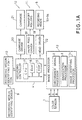
- Fig. 1A is a block diagram showing a major portion of a color copying machine employing an ink jet recording apparatus associated with a first embodiment of the present invention.
- Fig. 1B is a block diagram showing details of some elements shown in Fig. 1A.
- a color sensor 1 picks up an image on a document by separating each points of the image into three colors R, G and B, and by quantizing each color into an 8-bit signal.
- These R, G and B signals constitute an image recording signal which is inputted into an image processor 13.
- the image recording signal undergoes chrominance signal processing such as a logarithmic conversion, masking, UCR (Under Color Removal) and gamma correction in a chrominance signal processor 2 in the image processor 13.
- chrominance signal processing such as a logarithmic conversion, masking, UCR (Under Color Removal) and gamma correction in a chrominance signal processor 2 in the image processor 13.
- chrominance signal processing such as a logarithmic conversion, masking, UCR (Under Color Removal) and gamma correction in a chrominance signal processor 2 in the image processor 13.
- chrominance signal processing such as a logarithmic conversion, masking, UCR (Under Color Removal) and
- the R, G and B recording signals inputted into the image processor 13 are supplied to an image identifying processor 14 which identifies a text region that includes at least a part of a character or a line thinner than a predetermined thickness.
- a black signal generator 6 produces an 8-bit (256-level) black signal d by suppressing color components of the R, G and B signals.
- the black signal d is quantized into a binary signal by a black signal binarization portion 7, and is supplied to a black image identifying portion 8.
- the black image identifying portion 8 identifies continuous halftone regions, i.e., dot image regions, and text regions, and outputs 1-bit image identifying signals KB and KW in accordance with respective regions.
- the signals KB and KW are inputted into a recording controller 4.
- a recording medium identifying sensor 9 detects a recording medium.
- a recording medium For example, coated paper as a normal recording medium and noncoated paper like transparent paper for an overhead projector as a special recording medium are detected through an amount of light reflected by or transmitted through a recording medium.
- noncoated paper requires a special recording process because of low absorption power of ink.
- the detection signal produced by the recording medium identifying sensor 9 is fed to a recording medium identifying portion 10.
- the recording medium identifying portion 10 creates a 1-bit recording medium identification signal P from the detection signal, and transmits the signal P to the recording controller 4.
- the recording controller 4 controls the binary recording data signal created in accordance with the image identification signal and the recording medium identification signal, and controls driving of transportation of the recording medium and scanning of the recording head, so that optimal recording control is achieved depending on the type of an image and on the type of a recording medium.
- a black text region includes at least a part of a character and/or a line thinner than an useful line image.
- the present embodiment identifies a text region, a technique that identifies a character and a thin line independently is incorporated into the present invention.
- Color recording is generally carried out by additive color mixtures using color separated image recording signals.
- black text regions are generally reproduced by adding three colors C, M and Y or four colors K, C, M and Y.
- This embodiment uses four colors K, C, M and Y. Recording text regions by simply adding four color inks, however, poses the following problems:
- the present embodiment by using the image identifying processor 14, discriminates black text regions from continuous halftone regions (dot image regions) in an image to be recorded, and records the black text regions by using only black ink K.
- This makes it possible to reproduce an image whose black text regions have sufficient density (intensity) and resolution, and whose halftone regions are clear having high chroma and good gradation, when coated paper is used having an ink accepting layer formed on its surface to improve ink absorption and chromogenic characteristics.
- a special recording medium such as transparent paper having characteristics as mentioned in (4) above is used, recording black text regions with only black ink is not enough to reproduce high quality images. Accordingly, it is necessary to change recording control in such cases.
- the normal recording operation in which coated paper is used as a recording medium will be described in the order of processing by the image identifying processor 14, control of binary recording signals by the recording controller 4, and recording method.
- the chrominance signal processor 2 and the binarization processor 3 can be implemented by employing known techniques without imposing undue limit to the present invention, and so the description thereof will be omitted.
- Fig. 2A is a block diagram showing a detailed arrangement of the black signal generator 6.
- a maximum value detector 61 and a minimum value detector 62 compare, pixel by pixel, levels of 8-bit R, G and B signals inputted thereto, and produce a maximum value max(RGB) and a minimum value min(RGB), respectively.
- An adder 63 calculates the difference between the maximum value and the minimum value ⁇ max(RGB) - min(RGB) ⁇ of the R, G and B signal for each pixel.
- a multiplier 66 multiplies the difference by a fixed value ⁇ , and an adder 64 adds the result to max(RGB). When the added result exceeds 8-bit range, it is limited to 255 by a limiter 65. Thus, an 8-bit black signal d is obtained for each pixel.
- Fig. 2B is a diagram for explaining the process for obtaining the black signal d.
- a section A of Fig. 2B indicates a colored thin line, and a section B represents a black line.
- Equation (1) The physical meaning of equation (1) is as follows: It is rightly thought that the value ⁇ max(RGB) - min(RGB) ⁇ represents color and the value max(RGB) indicates a gray level or brightness.
- the value ⁇ max(RGB) - min(RGB) ⁇ is large, that is, color is present, the color is converted so as to shift toward white by equation (1) because the value is multiplied by ⁇ and is added to the value max(RGB). Accordingly, the greater the fixed value ⁇ is, the whiter a color pixel becomes. For this reason, the fixed value ⁇ is called a color suppression constant that represents a degree of suppressing of color of a pixel.
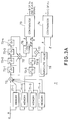
- the 8-bit black signal d is inputted to the binarization portion 7 whose detailed arrangement is shown in Fig. 3A.
- the black signal d is passed through 4 cascaded memories, and is sequentially delayed. Each memory delays the black signal d by one line.
- the four memories 73-1 - 73-4 produce four black signals associated with four pixels which are vertically aligned. The four black signals and the current black signal associated with a current pixel are summed up by an adder 72.
- the sum total outputted from the adder 72 is successively delayed by the amount corresponding to one pixel by four cascaded flip-flop circuits 73-1 - 73-4, and the outputs of the flip-flop circuits 73 and the adder 72 are further added by an adder 75.
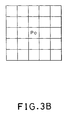
- the output of the adder 75 is a total sum of 25 pixels including a pixel of interest P 0 and its 24 neighboring pixels as shown in Fig. 3B.
- the black signal of the pixel of interest P 0 passes the memories 71-1 and 71-2, and flip-flops circuits 73-5 and 73-6, and is outputted from the flip-flop circuit 73-6.
- the black signal associated with the pixel of interest P 0 is delayed by the amount corresponding to 2 lines and 2 pixels than the current black signal.
- an average m of the black signals associated with the pixel of interest P 0 and its 24 neighboring pixels can be obtained by dividing the output of the adder 75 by 25 with a divider 76.
- the difference between the average m and the black signal d of the pixel of interest P 0 is obtained by an adder 77, and is transformed into its absolute value by an absolute-value circuit 78.
- > ⁇ C 0 when
- the second black signal B is a more sophisticated signal than the black signal d, which is obtained by converting the black signal d into a binary signal considering the neighboring pixels
- the differential signal C is a binary signal representing a rate of change in intensity levels at each pixel.
- the pixel may belong to a halftone region represented by dots, and hence, the two binary signals B and C are transferred to the black image identifying portion 8 so as to identify the region the pixel belongs to.
- Fig. 4A is a block diagram showing a detailed arrangement of the black image identifying portion 8.
- the second black signal B inputted as a binary signal is delayed by four line memories 80-1, 80-2, 80-3 and 80-4 which are connected in cascade, and each of which delays the signal by an amount corresponding to one line.
- the current input signal B and the output signals of the line memories 80-1 - 80-4 are further delayed by an amount corresponding to one pixel by flip-flops 81-0, 81-2, 81-4, 81-6 and 81-8, respectively, and the outputs of these flip-flops are further delayed by the amount of one pixel by flip-flops 81-1, 81-3, 81-5, 81-7 and 81-9, respectively.
- the signals B of eight neighboring pixels of the pixel of interest P 1 correspond to the inputs to the flip-flops 81-2, 81-4 and 81-6 and the outputs from the flip-flops 81-2, 81-6, 81-3, 81-5 and 81-7.
- the signals B of the 9 neighbors including the pixel of interest P 1 are inputted to a gate circuit 83-2.
- the signal B of a pixel corresponding to the output of the flip-flop 81-2 i.e., of a pixel delayed by one line than the pixel of interest P 1
- the signals B of 8-neighbors of that pixel are inputted to a gate circuit 83-1.
- the signal B of a pixel corresponding to the output of the flip-flop 82-6 i.e., of a pixel advanced by one line than the pixel of interest P 1
- the signals B of 8-neighbors of that pixel are inputted to a gate circuit 83-4.
- the gate circuits 83-1, 83-2 and 83-4 assign values S to the pixel delayed by one line than the pixel of interest P 1 , to the pixel of interest P 1 , and to the pixel advanced by one line than the pixel of interest P 1 , respectively.
- the value S takes one of the values 0 - 4 to represent the degree of isolation of the pixel of interest P 1 or the like from its 8 neighbors, that is, the possibility of having a binary value (0 or 1) reversal of those of the 8 neighbors.
- the possibility that the pixel of interest P 1 is an isolated dot increases consistently with the value of S. Accordingly, value 0 indicates a high possibility that the pixel of interest P 1 belongs to a text region because such a region is a group of one dimensional continuous dots. Correct judgement whether a pixel belongs to a text region or not, however, cannot be made on the basis of only one pixel, and hence, isolation indicators S assigned to each pixel are summed two-dimensionally so as to judge without error.
- an adder 85-1 adds three isolation indicators S corresponding to vertically aligned three pixels.
- the output of the adder 85-1 is delayed by six flip-flops 84-1 - 84-6 arranged in cascade so that six isolation indicators S are held in these flip-flops.
- the outputs of the six flipflops are added to the output of the adder 85-1 by an adder 85-2 to produce a total sum Pf.
- a pixel of interest is set as a pixel P 2 of Fig. 4B which is outputted from a flip-flop 89-4, that is, the pixel which has 2 line and 4 pixel delay with regard to the second black signal B of the pixel P 0 currently inputted to the flip-flop 81-0.
- the total sum Pf is a total of 3 ⁇ 7 pixels N 2 including the pixel of interest P 2 and its neighbors.
- This distinctive value Pf indicates a two-dimensional spatial frequency: a greater Pf value indicates that more frequent reversal between "0" and "1" of the binary signals B occur among the neighboring pixels, thus indicating the existence of more two-dimensionally isolated pixels.
- E is a third black signal representing a possibility that a pixel belongs to a text region
- K is a fixed value whose value is about 4 to 5.
- the judgement of equation (3) is carried out as follows: First, the Pf value of the pixel of interest P 2 is compared with the fixed value K by a comparator 86. Second, the differential signal C of the pixel of interest P 2 is obtained by delaying the binary signal C by 2 lines and 4 pixels by using memories 80-5 and 80-6 and flip-flops 82-1 - 82-4.
- the signals B and C of the pixel of interest P 2 are supplied to an AND gate 87 together with the distinctive value Pf of the pixel P 2 .
- the output of the AND gate 87 is a third black signal E of the pixel P 2 , which indicates that the pixel P 2 belongs to a text region.
- the third black signal E is further delayed by two 1-line delay memories 80-7 and 80-8 connected in cascade, and three third black signals E of vertically aligned three pixels P 2 , P 3 and P 4 in Fig. 4B are inputted to a black text signal generator 88.
- the second black signal B of the pixel P 3 is fed to the black text signal generator 88, which creates the final signals KB and KW.
- FIG. 5 is a circuit diagram illustrating a detailed arrangement of the gate circuit 83.
- Neighboring pixels a, b, c, d, e, f, g and h of the central pixel i correspond to input and output signals B of the flip-flops 81-0 - 81-9.
- EXCLUSIVE-OR gates 831-1 and 831-2 detect whether the pixel of interest i and its neighbors a and h reverse in the diagonal direction a, i and h.
- EXCLUSIVE-OR gates 831-1 and 831-2 When the outputs of both EXCLUSIVE-OR gates 831-1 and 831-2 are "1", the output of an AND gate 832-1 becomes “1", which indicates that the pixel of interest i is isolated from its neighbors in the diagonal direction a,i,h.
- EXCLUSIVE-OR gates 831-3 and 831-4 and an AND gate 832-2 detect isolation of the pixel i in the diagonal direction c,i,j
- EXCLUSIVE-OR gates 831-5 and 831-6 and an AND gate 832-3 detect isolation of the pixel i in the vertical direction b,i,g
- EXCLUSIVE-OR gates 831-7 and 831-8 and an AND gate 832-4 detect isolation of the pixel i in the horizontal direction d,i,e.
- AND gates 833-1 and 833-2 and OR gate 834 detect whether the pixel of interest i and its neighbors are consecutively “0" or “1” in the vertical direction b,i,g or in the horizontal direction d,i,e. When three pixels in these directions are consecutively "0" or "1", the output of the OR gate 834 becomes "0".
- the output of the OR gate 834 is ANDed with the outputs from the AND gate 832-1 - 832-4 by AND gates 835-1 - 835-4, respectively.
- the outputs of the AND gates 835-1 - 835-4 are added by an adder 836, thereby obtaining the S value indicating the degree of isolation of the pixel i as one of the numbers 0 - 4. The degree of isolation increases consistently with the value of S.
- the black text signal generator 88 produces two 1-bit signals KW and KB.
- the signal (a fourth black signal) KB indicates that a pixel of interest belongs to a black text region when it is "1".
- the signal KW indicates, when it is "1", that the second black signal B of a pixel of interest is "0", and that the third black signal E of at least one of the neighboring pixels of the pixel of interest is "1". This indicates that a text region exists adjacent to the pixel of interest.
- Fig. 6 three 1-bit third black signal E and the second black signal B (shown in Fig. 4A) are inputted to flip-flops 880-1, 880-3, 880-6 and 880-7, respectively.
- the outputs of the flip-flops 880-1, 880-3 and 880-6 are further delayed by flip-flops 880-2, 880-4 and 880-5.
- the output of the flip-flop 880-3 is set as a pixel of interest P 5 shown in Fig. 4B.
- the output of an OR gate 881 becomes "1" when at least one of the E signals of 8 neighboring pixels of the pixel of interest P 5 is "1".
- the second black signal B of the pixel of interest P 5 is produced from the flip-flop 880-7, and its inverted signal is inputted to an AND gate 882 together with the output of the OR gate 881.
- the signal KW of the pixel of interest P 5 is obtained.
- the inner processing for generating the signals KB and KW delays the second black signal B by 3 lines and 5 pixels from the pixel P 0 to P 5 as shown in Fig. 4B . For this reason, the recording signals outputted from the binarization processor 3 shown in Fig. 1B are delayed by that amount so as to synchronize the recording signal with the signals KB and KW.
- Fig. 7 shows delays for that purpose.
- Four binary recording signals 2C, 2Y, 2M and 2K are delayed by memories 40-1 - 40-4, and are fed to AND gates 41, 42 and 43, an OR gate 44 and an AND gate 45, respectively.
- outputs C, Y, M, K and [K] are produced from the AND gates 41, 42 and 43, the OR gate 44, and the AND gate 45, respectively, in response to the values of signals KB and KW as follows:
- Equation (4) means that a black dot is recorded when the black recording signal K determined as an OR of the signals 2K and KB is "1".
- the chrominance components of Y, M and C are contained in that pixel, they are suppressed so as to avoid color mixtures.
- KW of a pixel of interest is "1"
- the chrominance signals of that pixel are also suppressed so that neighboring dots of a black text region are not recorded, thus achieving clearer recording of the text region.
- This arrangement performs recording based on recording signals obtained as a result of above-described signal processing: the identification of a text region (or generation of the signals KB and KW) by the image identifying processor 14; and controlling of recording signals by the recording controller 4 in accordance with the result of the identification.
- Fig. 8 is a cross sectional side view showing a major portion of an ink jet recording apparatus associated with the first embodiment of the present invention.
- reference numerals 51 - 54 designate recording heads, each of which includes 64 ink orifices.
- an electrothermal converting element that generates thermal energy for ejecting ink.
- the recording heads 51, 52, 53 and 54 are for ejecting inks of black (K), cyan (C), magenta (M) and yellow (Y), respectively, and are supported by a carriage 21.
- the orifices of each head are aligned in the subscanning direction so that recording by a scanning of each head is superimposed on an identical area.
- the carriage 21 is slidably mounted on a pair of guide shafts 50, and is moved in the scanning direction (the direction normal to the sheet of Fig. 8) by a carriage motor described later.
- the recording heads 51 - 54 are electrically connected via the carriage 21 to the recording controller 4 described before with reference to Figs. 1A and 1B.
- the recording heads 51 - 54 are supplied with inks of respective colors from ink reservoirs in an ink supplying section 57 via a bundle of ink tubes 56 that can flexibly bend in accordance with the movement of the carriage 21.
- a recording medium 58 is successively incremented in the direction of the arrow to a recording position via a paper guide 110 by a pair of transport rollers 19 with a predetermined timing.
- the recording medium 58 is attracted to a transport belt 111 by electrostatic attraction, and is transferred with the movement of the belt 111 in synchronism with the transport roller 19.
- the recording medium 58 is successively located at the right place to be recorded.
- Fig. 1A described before is a block diagram showing an arrangement of the controlling portion of the ink jet recording apparatus as shown in Fig. 8.
- reference numeral 20 designates a carriage driver comprising a carriage motor that drives the carriage 21 via a carriage driving mechanism such as belts or pulleys.
- Reference numeral 22 denotes a head driver that produces ejection signals for each orifice of the recording heads 51 - 54 on the basis of recording data supplied from the recording controller 4.
- Reference numeral 18 designates a paper feed driver for driving the transport rollers 19 and the transport belt 111.
- the paper feed driver 18 is mainly composed of a motor.
- the recording controller 4 includes a CPU 17, an RAM 16 and an ROM 15.
- the CPU 17, communicating data with circuits shown in Fig. 7 as well as with a reading device and other devices of the recording apparatus, executes procedures for controlling these circuits and devices.
- the RAM 16 serves as working areas during the processing of the CPU 17, and the ROM 15 contains the processing procedures for the recording control as shown in Figs. 9A and 9B, or the like.
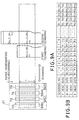
- Figs. 9A and 9B are a diagram and a table for illustrating a recording procedure of the ink jet recording apparatus as shown in Fig. 8.
- the recording heads 51 - 54 for ejecting inks of K, C, M and Y, respectively, are fixed to the carriage 21 so that recording areas formed by each recording head during a scanning overlaps completely.
- orifice lines 112 - 115 are shown for convenience as if they could be seen from above, although they cannot be actually seen from above.
- the recording heads 51 - 54 performs recording on a recording medium by ejecting inks from the orifices 112 - 115 in response to recording signals inputted in synchronism with the movement of the carriage 21.
- the recording medium 58 is incremented by a length L of the recording area every time the carriage 21 scans, by means of the pair of transport rollers 19 and the transport belt 111, and the recording is performed in the sequence of K, C, M and Y.
- a section of a color image of a head length L is formed in a first scanning on a first recording area of a length L by superimposing recording of recording signals K 1 , C 1 , M 1 and Y 1 by using the recording heads 51, 52, 53 and 54.
- paper incrementing is carried out by the amount equal to the head length L, and the next section of the color image is formed on a second recording area by the succeeding recording signals K 2 , C 2 , M 2 and Y 2 .
- processing the image recording signal by simply detecting text regions and controlling the recording signals in accordance with the detected results is not enough to realize a high quality recording of black text regions, when noncoated paper such as paper for plane paper copy, or transparent paper for an overhead projector which hinders spreading of ink dots and has a low chromogenic characteristic is used.
- the present invention offers another aspect of recording control based on recording medium identifying processing. This will be described below.
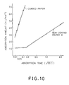
- Fig. 10 is a graph comparatively illustrating ink absorption characteristics of coated paper and noncoated paper A.
- the axis of abscissas represents a root of absorption time ( S )
- the axis of ordinates represents an absorption amount (nl/mm 2 ) of water based ink. It is found from Fig. 10 that coated paper, having ink accepting layer thereon, can absorb a great deal of ink in a short time, but that noncoated paper used in this embodiment requires a long time to absorb ink because of low initial absorption.
- Fig. 11 is a table showing examination results of spreading degrees of ink in terms of clearness of boundaries of two color inks when the two color inks are deposited substantially simultaneously onto a recording medium.
- circles indicate usability
- triangles indicate poor quality
- crosses indicate non-usability.
- the density of ink that can be recorded in a short time is less than 21 nl/mm 2 for noncoated paper, and less than 25 nl/mm 2 for coated paper.
- An ink absorption phenomenon are supposed to arise from mechanism shown in Figs. 12A and 12B.
- ink into paper is supposed to have steps of contact, collision, dot formation, penetration and drying.
- noncoated paper cannot absorb ink more than 11 - 12 l/mm 2 in less than 0.2 sec . Consequently, greater amount of ink simultaneously deposited on the noncoated paper runs, and the running ink is pulled to adjacent ink previously deposited on the paper, thus resulting in feathering at the boundaries of inks.
- Transparent paper can be processed into coated paper by providing ink accepting layer.
- nonabsorptive PET film on which absorptive resin is thinly coated is extensively used to ensure transparency for projection. Therefore, with regard to transparent paper which is coated for ink jet recording, the ink absorption amount cannot be increased. Although initial absorption rate can be increased, it soon saturates, and the absorption rate reduces beyond the saturation. In connection with this, vaporization of ink becomes necessary. Thus, high surface density ink deposition onto the transparent paper will cause feathering at boundaries as in noncoated paper, and hence, the surface density of ink deposition has its limit. In addition, spreading ratio as well as intensity level of ink cannot be increased as in coated paper.
- recording control is adjusted in accordance with a type of a recording medium which is indicated by the signal P transferred from the recording medium identifying portion 10 as shown in Fig. 1A.
- recording method as shown in Figs. 13A and 13B is employed.
- Figs. 13A and 13B are figures corresponding to Figs. 9A and 9B.
- the first scanning (1-1) performs color recording to a first recording region with the recording heads 51, 52, 53 and 54 to which recording signals K 1 , C 1 , M 1 and Y 1 are supplied.
- these recording signals are formed by processing input signals in accordance with identification result of a text region or a halftone region by the image identifying processor 14.
- this first scanning although four inks are simultaneously deposited, reduction in resolution can be prevented.
- recording of halftone regions is also carried out with restricted ink ejection. Accordingly, pulling between different color inks is reduced so that an image of good gradation can be reproduced although intensity level may slightly reduce.
- a second scanning (1-2) is performed on the first recording area without incrementing paper.
- the second scanning (1-2) only [K] 1 data that is defined as K data of text regions (excluding K data of halftone regions), as shown in fig. 7, are recorded again by using the K head 51.
- the data [K] 1 may be produced either by reading the same position of the document once again, or by storing the text regions of the first data K 1 in an RAM or the like, and by reading them at the second recording.
- K ink is deposited again on the previously formed text regions by K ink as mentioned above.
- Fig. 14 illustrates recording of a halftone region formed by depositing K, C and Y inks once and of a text region formed by depositing K ink twice. It is found from this figure that although the second K ink is deposited on the first K ink before the first K ink has been fixed (absorbed and dried), intensity level can be increased with little reduction in resolution even if the second ink is somewhat pulled by the first ink.
- the paper is incremented by the length L as shown in Figs. 13A and 13B.
- a third scanning (2-1) and a fourth scanning (2-2) are executed so that recording onto a second recording area of length L is achieved.
- text regions are recorded by double scanning so that they are recorded twice.
- sharp reduction in recording rate can be prevented by taking the following steps: first, enabling recording by using reciprocating scanning; second, storing [K] data of text regions in a memory; and third, the [K] data is over-printed during backward subscanning in a reciprocating scanning.
- thickness enhancement in text regions is possible without increasing the number of scanning by superimposing two color inks K and C for text regions, and by printing halftone regions with four inks K, C, M and Y.
- decrease in recording speed can be prevented.
- text regions may be printed by superimposing three color inks K, M and C.
- Fig. 15 is a perspective view of a recording head associated with a second embodiment.
- the recording head includes four ink heads integrally arranged into a head cartridge which is adapted for full-color recording. More specifically, it integrally includes recording heads 61 - 64, each corresponding to one of the black (K), cyan (C), magenta (M), and yellow (Y), and their ink reservoirs.
- Each recording head includes 128 orifices aligned in the subscanning direction.
- This recording head is a disposable cartridge type including ink reservoirs as its integral parts, and hence, when ink is exhausted, the cartridge is replaced with another cartridge incorporating ink reservoirs and recording heads.
- High resolution recording as in this embodiment requires high registration accuracy between recording heads.
- four color recording heads are integrally replaced as in this embodiment, it becomes possible to perform precise registration. This enables an apparatus using a disposable type recording head to achieve high quality image recording by utilizing its capability to the full extent.
- a recording method of the first embodiment is replaced by a new recording method, which is one of the features of the present invention. Accordingly, it is not necessary to change the construction of the image identifying portion.
- Figs. 16A and 16B are a diagram and a table illustrating a recording method by using the recording heads shown in Fig. 15.
- the recording density of 600 DPI specifies a side length of a square pixel at 42.33 ⁇ m, a droplet diameter at 31 ⁇ m, and its volume at 14.2 pl.
- each of the recording head 61 - 64 is divided into two sections so that an identical recording area is recorded by two different heads corresponding to two color inks, in addition to black ink [K] of text regions.
- forward sections F of the recording heads 61, 63 and 62 corresponding to K, M and C inks, and rear sections R of the recording heads 64 and 61 corresponding to Y and K inks can record to the same recording area.
- 153 times of scanning with the data sequence as shown in Fig. 16B makes it possible to complete recording to A3 size paper.
- Fig. 17 is a perspective view showing an ink jet recording apparatus on which the recording head shown in Figs. 15 and 16A can be mounted.
- a carriage 72 slidably mounted on guide shafts 74, and is driven by a carriage motor 76 so that the recording heads 61 - 64 can scan on a recording area.
- the number of recording areas assigned to an area corresponding to the head length can be arbitrarily determined.
- This setting can be executed by adjusting the amount of paper incrementing and recording signals supplied to the recording heads by the recording controller 4 having the arrangement as shown in Figs. 1A and 1B.
- This enables the apparatus to record onto a recording medium of poor ink absorption power, such as plane paper or transparent films for an OHP, thus diversifying types of recording mediums that can be used.
- an apparatus of this embodiment increments a recording medium by the length of a divided recording area for each scanning, and performs recording with predetermined orifices corresponding to the recording area by using a plurality of recording heads in response to the incrementation of the recording medium.
- an ink deposition area in one scanning can be narrowed without scarcely increasing the number of scanning compared with a recording method in which each color ink is ejected over the entire length of the head without dividing the recording heads into sections.
- the present embodiment has an advantage to restrict paper undulation.
- increasing amount of ink ejection or of ink deposit causes paper undulation phenomenon, because the paper swells, expands or contracts by accepting ink.
- This embodiment can limit the undulation because an area of a maximum ink deposition density at each instant becomes smaller than that when the recording head is not divided into sections. Consequently, it is not necessary to unduly separate the interval between the head and the recording medium. This makes it possible to improve landing precision of ink and the quality of images.
- ink deposition density becomes very high in superimposing recording using a plurality of color inks. Therefore, in a conventional method in which paper incrementing is performed each time a predetermined times of scanning are completed so that recording of the next line is started, ink accepting amount is greatly different between the lines. As a result, image degradation (intensity unevenness) at the joint boundary of the scanning lines, which is supposed to be caused by an ink absorbing phenomenon of the next line, is liable to occur at that boundary, and ink running in the paper incrementing direction of the preceding line becomes large.
- [K] 1 data K only for text regions
- K 1 data K for both text and halftone regions
- a dimension of a square pixel is 84. 67 ⁇ m; a diameter of a pixel dot is 121 nm; a diameter of a droplet is 60 nm, a volume of the droplet is 113 pl; and the surface density of monochromatic ink is 15.8 nl/mm 2 .
- the volume of droplets is set at a little smaller side, and ink deposition is performed twice in text regions, but once in halftone regions.
- ink deposition is performed twice in text regions, but once in halftone regions.
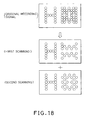
- another method can be used in this embodiment rather than reducing the ink ejection volume: halftone regions are recorded by separately depositing ink twice in staggered patterns in a first scanning and in counter-staggered patterns in a second scanning as shown in Fig. 18; and text regions are recorded by depositing ink twice using the same data.
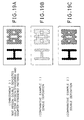
- Figs. 19A -19C comparatively illustrate ink spreading when recording is performed on transparent paper:
- Fig. 19A illustrates a sample of the third embodiment in which the text region is printed by the double deposition of ink, and the halftone region is printed by separately depositing ink in a staggered pattern and in a counter-staggered pattern;
- Fig. 19B is a sample of single deposition of ink;
- Fig. 19A is a sample of simple double deposition of ink.
- K ink head only one K ink head is used, another K ink recording head can be added so that the scanning number can be reduced.
- identification of text regions in this embodiment can be carried out without using portions associated with color signals in the image identification of the first embodiment, or other known process for identification can be used.
- Ink jet recording apparatuses disclosed in the embodiments above can be applied not only to copying machines or to other machines employing printers, such as facsimiles, but also to word processors, microcomputers, or other information processing systems using these machines as output devices.
- the present invention achieves distinct effect when applied to a recording head or a recording apparatus which has means for generating thermal energy such as electrothermal transducers or laser light, and which causes changes in ink by the thermal energy so as to eject ink. This is because such a system can achieve a high density and high resolution recording.
- the on-demand type apparatus has electrothermal transducers, each disposed on a sheet or liquid passage that retains liquid (ink), and operates as follows: first, one or more drive signals are applied to the electrothermal transducers to cause thermal energy corresponding to recording information; second, the thermal energy induces sudden temperature rise that exceeds the nucleate boiling so as to cause the film boiling on heating portions of the recording head; and third, bubbles are grown in the liquid (ink) corresponding to the drive signals. By using the growth and collapse of the bubbles, the ink is expelled from at least one of the ink ejection orifices of the head to form one or more ink drops.
- the drive signal in the form of a pulse is preferable because the growth and collapse of the bubbles can be achieved instantaneously and suitably by this form of drive signal.
- a drive signal in the form of a pulse those described in U.S. patent Nos. 4,463,359 and 4,345,262 are preferable.
- the rate of temperature rise of the heating portions described in U.S. patent No. 4,313,124 be adopted to achieve better recording.
- U.S. patent Nos. 4,558,333 and 4,459,600 disclose the following structure of a recording head, which is incorporated to the present invention: this structure includes heating portions disposed on bent portions in addition to a combination of the ejection orifices, liquid passages and the electrothermal transducers disclosed in the above patents. Moreover, the present invention can be applied to structures disclosed in Japanese Patent Application Laying-open Nos. 123670/1984 and 138461/1984 in order to achieve similar effects.
- the former discloses a structure in which a slit common to all the electrothermal transducers is used as ejection orifices of the electrothermal transducers, and the latter discloses a structure in which openings for absorbing pressure waves caused by thermal energy are formed corresponding to the ejection orifices.
- the present invention can be also applied to a so-called full-line type recording head whose length equals the maximum length across a recording medium.
- a recording head may consists of a plurality of recording heads combined together, or one integrally arranged recording head.
- the present invention can be applied to various serial type recording heads: a recording head fixed to the main assembly of a recording apparatus; a conveniently replaceable chip type recording head which, when loaded on the main assembly of a recording apparatus, is electrically connected to the main assembly, and is supplied with ink therefrom; and a cartridge type recording head integrally including an ink reservoir.
- a recovery system or a preliminary auxiliary system for a recording head as a constituent of the recording apparatus because they serve to make the effect of the present invention more reliable.
- the recovery system are a capping means and a cleaning means for the recording head, and a pressure or suction means for the recording head.
- the preliminary auxiliary system are a preliminary heating means utilizing electrothermal transducers or a combination of other heater elements and the electrothermal transducers, and a means for carrying out preliminary ejection of ink independently of the ejection for recording. These systems are effective for reliable recording.
- the number and type of recording heads to be mounted on a recording apparatus can be also changed. For example, only one recording head corresponding to a single color ink, or a plurality of recording heads corresponding to a plurality of inks different in color or concentration can be used.
- the present invention can be effectively applied to an apparatus having at least one of the monochromatic, multi-color and full-color modes.
- the monochromatic mode performs recording by using only one major color such as black.
- the multi-color mode carries out recording by using different color inks, and the full-color mode performs recording by color mixing.
- inks that are liquid when the recording signal is applied can be used: for example, inks can be employed that solidify at a temperature lower than the room temperature and are softened or liquefied in the room temperature. This is because in the ink jet system, the ink is generally temperature adjusted in a range of 30°C - 70°C so that the viscosity of the ink is maintained at such a value that the ink can be ejected reliably.
- the present invention can be applied to such apparatus where the ink is liquefied just before the ejection by the thermal energy as follows so that the ink is expelled from the orifices in the liquid state, and then begins to solidify on hitting the recording medium, thereby preventing the ink evaporation: the ink is transformed from solid to liquid state by positively utilizing the thermal energy which would otherwise cause the temperature rise; or the ink, which is dry when left in air, is liquefied in response to the thermal energy of the recording signal.
- the ink may be retained in recesses or through holes formed in a porous sheet as liquid or solid substances so that the ink faces the electrothermal transducers as described in Japanese Patent Application Laying-open Nos. 56847/1979 or 71260/1985.
- the present invention is most effective when it uses the film boiling phenomenon to expel the ink.
- the ink jet recording apparatus of the present invention can be employed not only as an image output terminal of an information processing device such as a computer, but also as an output device of a copying machine including a reader, and as an output device of a facsimile apparatus having a transmission and receiving function.
Landscapes
- Engineering & Computer Science (AREA)
- Multimedia (AREA)
- Signal Processing (AREA)
- Physics & Mathematics (AREA)
- General Engineering & Computer Science (AREA)
- Theoretical Computer Science (AREA)
- General Physics & Mathematics (AREA)
- Mathematical Physics (AREA)
- Quality & Reliability (AREA)
- Ink Jet (AREA)
- Particle Formation And Scattering Control In Inkjet Printers (AREA)
- Accessory Devices And Overall Control Thereof (AREA)
- Facsimile Image Signal Circuits (AREA)
Claims (20)
- Appareil d'enregistrement à jet d'encre pour effectuer un enregistrement sur un support d'enregistrement en déposant de l'encre sur le support d'enregistrement en réponse à des données d'enregistrement, ledit appareil comportant :une pluralité de têtes d'enregistrement (51-54) destinées à éjecter des encres, ladite pluralité de têtes d'enregistrement comprenant une tête d'enregistrement destinée à éjecter une encre noire et une tête d'enregistrement destinée à éjecter une encre colorée autre que l'encre noire ;des moyens d'identification d'images (6, 7, 14) destinés à identifier des données d'enregistrement correspondant à une zone de texte qui comprend au moins une partie d'au moins l'un d'un caractère et d'une ligne ;des moyens (2, 3) de traitement de données destinés à traiter lesdites données d'enregistrement en données qui correspondent à ladite pluralité de têtes d'enregistrement, sur la base d'un résultat d'identification par lesdits moyens d'identification d'images, dans lesquels lesdites données d'enregistrement correspondant à ladite zone de texte identifiée sont traitées en données qui correspondent à ladite tête d'enregistrement destinée à éjecter de l'encre noire ;des moyens (4) de commande d'enregistrement destinés à commander une opération d'enregistrement en utilisant ladite pluralité de têtes d'enregistrement, sur la base desdites données traitées par lesdits moyens de traitement de données et correspondant à ladite pluralité de têtes d'enregistrement ; et caractérisé en ce que lesdits moyens de commande d'enregistrement sont conçus pour commander l'opération d'enregistrement afin que l'opération d'enregistrement utilisant ladite tête d'enregistrement destinée à éjecter de l'encre noire soit effectuée plusieurs fois par rapport à ladite zone de texte identifiée.
- Appareil selon la revendication 1, dans lequel ladite tête d'enregistrement destinée à éjecter de l'encre noire enregistre sur ladite zone de texte du support d'enregistrement avec une densité d'encre plus épaisse que celle enregistrée sur le support d'enregistrement par l'une de ladite pluralité de têtes d'enregistrement correspondant à une encre colorée autre que l'encre noire.
- Appareil selon la revendication 1 ou la revendication 2, dans lequel lesdits moyens de commande d'enregistrement commandent l'opération d'enregistrement afin que lesdites données correspondant à ladite tête d'enregistrement destinée à éjecter de l'encre noire soient produites par lesdits moyens de traitement de données plusieurs fois pour la pluralité d'opérations d'enregistrement devant être effectuées pour la zone de texte.
- Appareil selon la revendication 1 ou la revendication 2, dans lequel lesdits moyens de commande d'enregistrement commandent l'opération d'enregistrement afin que les mêmes données soient utilisées pour effectuer la pluralité d'opérations d'enregistrement pour la même aire de ladite zone de texte.
- Appareil selon l'une quelconque des revendications précédentes, dans lequel lesdits moyens de commande d'enregistrement commandent l'opération d'enregistrement afin que l'opération d'enregistrement soit effectuée par un balayage utilisant ladite pluralité de têtes d'enregistrement et par un balayage n'utilisant que ladite tête d'enregistrement destinée à éjecter de l'encre noire parmi ladite pluralité de têtes d'enregistrement, pour une zone prédéterminée du support d'enregistrement.
- Appareil selon l'une quelconque des revendications précédentes, dans lequel, pour une zone prédéterminée du support d'enregistrement, lesdits moyens de commande d'enregistrement commandent l'opération d'enregistrement d'une manière telle qu'une pluralité d'opérations de balayage sont exécutées sur ladite zone prédéterminée par ladite pluralité de têtes d'enregistrement en diminuant la quantité d'encre éjectée par ladite tête d'enregistrement destinée à éjecter une encre autre que l'encre noire par rapport à la quantité d'encre éjectée par ladite tête d'enregistrement destinée à éjecter de l'encre noire.
- Appareil selon l'une quelconque des revendications précédentes, caractérisé par des moyens d'identification (9) destinés à identifier le type dudit support d'enregistrement et en ce que lesdits moyens de commande d'enregistrement commandent, lorsque ledit support d'enregistrement est à faible absorption d'encre, lesdites têtes d'enregistrement afin que chaque composante de couleur non noire dudit signal de données d'enregistrement correspondant à ladite zone en demi-teintes soit enregistrée une fois, tandis qu'une composante noire dudit signal de données d'enregistrement correspondant auxdites zones de texte est enregistrée deux fois.
- Appareil selon l'une quelconque des revendications précédentes, caractérisé en ce que lesdites têtes d'enregistrement comprennent quatre têtes, dont chacune correspond à chacune de quatre couleurs noire, cyan, magenta et jaune, et est divisée en une pluralité de sections comprenant chacune une pluralité d'orifices alignés suivant une direction de balayage secondaire, et lesdits moyens de commande d'enregistrement commandent lesdites têtes d'enregistrement afin que des sections sélectionnées éjectent séquentiellement de l'encre.
- Appareil selon l'une quelconque des revendications précédentes, dans lequel lesdites têtes d'enregistrement comprennent des moyens à transducteurs électrothermiques destinés à appliquer de l'énergie thermique aux encres devant être éjectées.
- Procédé d'enregistrement à jet d'encre pour former une image sur un support d'enregistrement en utilisant une pluralité de têtes d'enregistrement (51-54) destinées à éjecter des encres, ladite pluralité de têtes d'enregistrement comprenant une tête d'enregistrement destinée à éjecter une encre noire et une tête d'enregistrement destinée à éjecter une encre colorée autre que l'encre noire, ledit procédé comprenant les étapes dans lesquelles :dans lequel, dans ladite étape de commande de l'opération d'enregistrement, l'opération d'enregistrement utilisant ladite tête d'enregistrement destinée à éjecter de l'encre noire est effectuée plusieurs fois par rapport à ladite zone de texte identifiée.on identifie des données d'enregistrement correspondant à une zone de texte qui comprend au moins une partie d'au moins l'un d'ùn caractère et d'une ligne ;on traite lesdites données d'enregistrement en données qui correspondent à ladite pluralité de têtes d'enregistrement, sur la base d'un résultat d'identification par ladite étape d'identification d'image, lesdites données d'enregistrement correspondant à ladite zone de texte identifiée étant traitée en données qui correspondent à ladite tête d'enregistrement destinée à éjecter de l'encre noire ;on commande une opération d'enregistrement en utilisant ladite pluralité de têtes d'enregistrement, sur la base desdites données correspondant à ladite pluralité de têtes d'enregistrement ;
- Procédé selon la revendication 10, dans lequel ladite tête d'enregistrement destinée à éjecter de l'encre noire enregistre sur ladite zone de texte du support d'enregistrement avec une densité d'encre plus épaisse que celle enregistrée sur le support d'enregistrement par l'une de ladite pluralité de têtes d'enregistrement correspondant à une encre colorée autre que l'encre noire.
- Procédé selon la revendication 10 ou la revendication 11, dans lequel, dans ladite étape de commande de l'opération d'enregistrement, lesdites données correspondant à ladite tête d'enregistrement destinées à éjecter de l'encre noire sont produites plusieurs fois dans ladite étape de traitement de données afin d'effectuer la pluralité d'opérations d'enregistrement pour la zone de texte.
- Procédé selon la revendication 10, 11 ou 12, dans lequel, dans ladite étape de commande de l'opération d'enregistrement, les mêmes données sont utilisées pour effectuer la pluralité d'opérations d'enregistrement pour la même aire de ladite zone de texte.
- Procédé selon l'une quelconque des revendications 10 à 13, dans lequel, dans ladite étape de commande de l'opération d'enregistrement, l'opération d'enregistrement est effectuée par un balayage utilisant ladite pluralité de têtes d'enregistrement et par un balayage n'utilisant que ladite tête d'enregistrement destinée à éjecter de l'encre noire parmi ladite pluralité de têtes d'enregistrement, pour une zone prédéterminée du support d'enregistrement.
- Procédé selon l'une quelconque des revendications 10 à 14, dans lequel, pour une zone prédéterminée du support d'enregistrement, l'opération d'enregistrement est commandée d'une manière telle qu'une pluralité d'opérations de balayage sont effectuées sur ladite zone prédéterminée par ladite pluralité de têtes d'enregistrement avec une diminution de la quantité d'encre éjectée par ladite tête d'enregistrement destinée à éjecter une encre autre que l'encre noire par rapport à la quantité d'encre éjectée par ladite tête d'enregistrement destinée à éjecter de l'encre noire.
- Procédé selon l'une quelconque des revendications 10 à 15, caractérisé en ce que chacune desdites têtes d'enregistrement est divisée en une pluralité de sections, et les étapes destinées à expulser de l'encre noire et une pluralité d'encres sont effectuées séquentiellement depuis des sections inférieures vers des sections supérieures, par incrémentation du support d'enregistrement de la longueur des sections.
- Procédé selon l'une quelconque des revendications 10 à 16, caractérisé en ce que la zone de texte est enregistrée par dépôt d'encre noire deux fois sur la même aire d'enregistrement, et la zone en demi-teintes est enregistrée par dépôt séparé d'encres colorées selon une configuration étagée et selon une configuration étagée en sens opposés, en lesquelles la zone en demi-teintes est divisée.
- Procédé selon l'une quelconque des revendications 10 à 17, caractérisé en outre en ce qu'il comprend l'étape d'identification du type dudit support d'enregistrement.
- Procédé selon la revendication 18, caractérisé en ce que, lorsque le support d'enregistrement est détecté comme étant du type présentant une faible capacité d'absorption d'encre, chaque composante de couleur dudit signal de données d'enregistrement correspondant à ladite zone en demi-teintes est enregistrée une fois, tandis que la composante noire dudit signal de données d'enregistrement correspondant à ladite zone de texte est enregistrée deux fois.
- Procédé selon l'une quelconque des revendications 10 à 19, dans lequel l'encre est éjectée par des moyens à transducteurs électrothermiques qui appliquent de l'énergie thermique à leurs encres.
Applications Claiming Priority (4)
| Application Number | Priority Date | Filing Date | Title |
|---|---|---|---|
| JP2329747A JP2960537B2 (ja) | 1990-11-30 | 1990-11-30 | インクジェット記録装置 |
| JP329747/90 | 1990-11-30 | ||
| JP32974790 | 1990-11-30 | ||
| EP91311003A EP0488724B1 (fr) | 1990-11-30 | 1991-11-28 | Appareil et méthode d'enregistrement à jet d'encre |
Related Parent Applications (2)
| Application Number | Title | Priority Date | Filing Date |
|---|---|---|---|
| EP91311003A Division EP0488724B1 (fr) | 1990-11-30 | 1991-11-28 | Appareil et méthode d'enregistrement à jet d'encre |
| EP91311003.7 Division | 1991-11-28 |
Publications (2)
| Publication Number | Publication Date |
|---|---|
| EP0706889A1 EP0706889A1 (fr) | 1996-04-17 |
| EP0706889B1 true EP0706889B1 (fr) | 2002-04-03 |
Family
ID=18224835
Family Applications (2)
| Application Number | Title | Priority Date | Filing Date |
|---|---|---|---|
| EP91311003A Expired - Lifetime EP0488724B1 (fr) | 1990-11-30 | 1991-11-28 | Appareil et méthode d'enregistrement à jet d'encre |
| EP95202960A Expired - Lifetime EP0706889B1 (fr) | 1990-11-30 | 1991-11-28 | Appareil d'enregistrement à jet d'encre et méthode |
Family Applications Before (1)
| Application Number | Title | Priority Date | Filing Date |
|---|---|---|---|
| EP91311003A Expired - Lifetime EP0488724B1 (fr) | 1990-11-30 | 1991-11-28 | Appareil et méthode d'enregistrement à jet d'encre |
Country Status (4)
| Country | Link |
|---|---|
| US (1) | US5745145A (fr) |
| EP (2) | EP0488724B1 (fr) |
| JP (1) | JP2960537B2 (fr) |
| DE (2) | DE69132978T2 (fr) |
Families Citing this family (21)
| Publication number | Priority date | Publication date | Assignee | Title |
|---|---|---|---|---|
| JP2894005B2 (ja) * | 1991-06-14 | 1999-05-24 | ブラザー工業株式会社 | 印字装置 |
| DE69333194T2 (de) * | 1992-03-31 | 2004-07-15 | Canon K.K. | Tintenstrahlverfahren und -vorrichtung |
| JPH0615817A (ja) * | 1992-06-30 | 1994-01-25 | Fuji Xerox Co Ltd | インクジェット記録装置 |
| JP3368066B2 (ja) * | 1994-09-06 | 2003-01-20 | キヤノン株式会社 | 画像記録装置および画像記録方法 |
| JPH09164705A (ja) * | 1995-12-14 | 1997-06-24 | Mitsubishi Electric Corp | インクジェット記録装置 |
| DE69725374T2 (de) * | 1996-04-19 | 2004-08-12 | Canon K.K. | Tintenstrahldruckverfahren und -gerät unter Verwendung einer Druckqualität verbessernden Flüssigkeit |
| US6010207A (en) * | 1996-08-30 | 2000-01-04 | Citizen Watch Co., Ltd. | Color printer and printing method using the same |
| JP3839989B2 (ja) | 1998-03-11 | 2006-11-01 | キヤノン株式会社 | 画像処理方法及び装置及び記録方法とその装置 |
| US5999705A (en) * | 1998-04-15 | 1999-12-07 | Lexmark International, Inc. | Method of interlaced printing using an ink jet printer |
| JP4174103B2 (ja) * | 1998-07-30 | 2008-10-29 | キヤノン株式会社 | インクジェット記録装置およびインクジェット記録方法 |
| US6318827B1 (en) * | 1998-10-28 | 2001-11-20 | Hewlett-Packard Company | Method of improving print quality by selectively changing print direction |
| US6540316B1 (en) | 1999-06-04 | 2003-04-01 | Canon Kabushiki Kaisha | Liquid discharge head and liquid discharge apparatus |
| US6203151B1 (en) | 1999-06-08 | 2001-03-20 | Hewlett-Packard Company | Apparatus and method using ultrasonic energy to fix ink to print media |
| US7768669B2 (en) * | 2000-09-12 | 2010-08-03 | Canon Kabushiki Kaisha | Image processing apparatus, printer using this apparatus, digital camera using this apparatus, consumable material holder for printer, and printer for digital camera |
| NL1017480C2 (nl) * | 2001-03-02 | 2002-09-03 | My Cartons Bv | Werkwijze voor het drukken van een kleurenafbeelding en inkt voor toepassing bij deze werkwijze. |
| US6776468B2 (en) * | 2001-08-27 | 2004-08-17 | Eastman Kodak Company | Method and apparatus of optimizing discrete drop volumes for multidrop capable inkjet printers |
| JP2003226002A (ja) * | 2002-02-04 | 2003-08-12 | Seiko Epson Corp | 印刷装置、被印刷体、記憶素子、コンピュータプログラム、コンピュータシステム、及び、印刷方法 |
| US6793310B2 (en) | 2002-04-08 | 2004-09-21 | Creo Americas, Inc. | Certified proofing |
| US7032988B2 (en) | 2002-04-08 | 2006-04-25 | Kodak Graphic Communications Canada Company | Certified proofing |
| US9258455B2 (en) * | 2008-05-08 | 2016-02-09 | Ricoh Company, Ltd. | Mechanism for K-only object rendering in a high-speed color controller |
| WO2014117815A1 (fr) * | 2013-01-29 | 2014-08-07 | Hewlett-Packard Development Company, L.P. | Imprimante et procédé de traitement d'une image à imprimer |
Family Cites Families (28)
| Publication number | Priority date | Publication date | Assignee | Title |
|---|---|---|---|---|
| US4087825A (en) * | 1976-05-27 | 1978-05-02 | International Business Machines Corporation | Ink jet printing intensity modulation |
| CA1127227A (fr) | 1977-10-03 | 1982-07-06 | Ichiro Endo | Procede d'enregistrement a jet liquide et appareil d'enregistrement |
| JPS5936879B2 (ja) | 1977-10-14 | 1984-09-06 | キヤノン株式会社 | 熱転写記録用媒体 |
| US4330787A (en) | 1978-10-31 | 1982-05-18 | Canon Kabushiki Kaisha | Liquid jet recording device |
| US4345262A (en) | 1979-02-19 | 1982-08-17 | Canon Kabushiki Kaisha | Ink jet recording method |
| US4463359A (en) | 1979-04-02 | 1984-07-31 | Canon Kabushiki Kaisha | Droplet generating method and apparatus thereof |
| US4313124A (en) | 1979-05-18 | 1982-01-26 | Canon Kabushiki Kaisha | Liquid jet recording process and liquid jet recording head |
| US4554593A (en) * | 1981-01-02 | 1985-11-19 | International Business Machines Corporation | Universal thresholder/discriminator |
| US4558333A (en) | 1981-07-09 | 1985-12-10 | Canon Kabushiki Kaisha | Liquid jet recording head |
| US4642681A (en) * | 1982-10-08 | 1987-02-10 | Canon Kabushiki Kaisha | Color image processing apparatus for generating color output signals and a black output signal in a mutually exclusive manner |
| JPS59123670A (ja) | 1982-12-28 | 1984-07-17 | Canon Inc | インクジエツトヘツド |
| JPS59138461A (ja) | 1983-01-28 | 1984-08-08 | Canon Inc | 液体噴射記録装置 |
| JPS59146262A (ja) * | 1983-02-09 | 1984-08-22 | Hitachi Ltd | 2値1多値画像領域判定処理方式 |
| US4617580A (en) * | 1983-08-26 | 1986-10-14 | Canon Kabushiki Kaisha | Apparatus for recording on different types of mediums |
| US4721968A (en) * | 1983-09-22 | 1988-01-26 | Canon Kabushiki Kaisha | Ink jet transparency-mode recorder |
| JPS6071260A (ja) | 1983-09-28 | 1985-04-23 | Erumu:Kk | 記録装置 |
| DE3477118D1 (en) * | 1984-04-27 | 1989-04-13 | Siemens Ag | Ink-writing apparatus reproducing multicolour characters and/or patterns |
| US4578713A (en) * | 1984-07-20 | 1986-03-25 | The Mead Corporation | Multiple mode binary image processing |
| US4926251A (en) * | 1987-04-07 | 1990-05-15 | Kabushiki Kaisha Toshiba | Color image processing apparatus with image corrector |
| US4748453A (en) * | 1987-07-21 | 1988-05-31 | Xerox Corporation | Spot deposition for liquid ink printing |
| JPH024523A (ja) * | 1988-06-22 | 1990-01-09 | Canon Inc | インクジェット記録方法及び該方法に用いる装置 |
| US5153925A (en) * | 1989-04-27 | 1992-10-06 | Canon Kabushiki Kaisha | Image processing apparatus |
| US5129048A (en) * | 1989-07-31 | 1992-07-07 | Eastman Kodak Company | Efficient data storage system for gray-scale printers |
| US5125072A (en) * | 1989-07-31 | 1992-06-23 | Eastman Kodak Company | Efficient data storage system for gray-scale printers |
| JPH0372778A (ja) * | 1989-08-11 | 1991-03-27 | Fuji Xerox Co Ltd | 画像処理装置の領域識別方式 |
| US5146554A (en) * | 1989-09-29 | 1992-09-08 | Eastman Kodak Company | Page memory control in a raster image processor employed for digital halftoning |
| EP0429283B1 (fr) * | 1989-11-20 | 1999-01-20 | Canon Kabushiki Kaisha | Appareil de traitement d'images |
| JP3100391B2 (ja) * | 1990-08-15 | 2000-10-16 | 株式会社リコー | カラー画像の領域分離装置 |
-
1990
- 1990-11-30 JP JP2329747A patent/JP2960537B2/ja not_active Expired - Fee Related
-
1991
- 1991-11-28 EP EP91311003A patent/EP0488724B1/fr not_active Expired - Lifetime
- 1991-11-28 DE DE69132978T patent/DE69132978T2/de not_active Expired - Lifetime
- 1991-11-28 DE DE69122721T patent/DE69122721T2/de not_active Expired - Lifetime
- 1991-11-28 EP EP95202960A patent/EP0706889B1/fr not_active Expired - Lifetime
-
1996
- 1996-12-03 US US08/758,345 patent/US5745145A/en not_active Expired - Lifetime
Also Published As
| Publication number | Publication date |
|---|---|
| JPH04201350A (ja) | 1992-07-22 |
| DE69122721D1 (de) | 1996-11-21 |
| EP0706889A1 (fr) | 1996-04-17 |
| JP2960537B2 (ja) | 1999-10-06 |
| DE69132978D1 (de) | 2002-05-08 |
| DE69122721T2 (de) | 1997-03-13 |
| EP0488724B1 (fr) | 1996-10-16 |
| EP0488724A2 (fr) | 1992-06-03 |
| DE69132978T2 (de) | 2002-10-17 |
| EP0488724A3 (en) | 1992-12-16 |
| US5745145A (en) | 1998-04-28 |
Similar Documents
| Publication | Publication Date | Title |
|---|---|---|
| EP0706889B1 (fr) | Appareil d'enregistrement à jet d'encre et méthode | |
| US5568169A (en) | Method and apparatus using two different black inks to reduce intercolor bleeding and provide high quality edge definition with thermal ink jet systems | |
| JP3313952B2 (ja) | インクジェット記録装置 | |
| EP0919388B1 (fr) | Appareil d'enregistrement d'image | |
| US5739828A (en) | Ink jet recording method and apparatus having resolution transformation capability | |
| US5992971A (en) | Ink jet recording method and apparatus | |
| JP4012023B2 (ja) | インクジェット記録方法、記録システム、インクジェット記録装置、制御方法およびプログラム | |
| JP4486280B2 (ja) | 印刷装置、印刷方法及びそのためのプログラムを記録した記録媒体並びにプログラム | |
| EP0830948A1 (fr) | Imprimante a jet d'encre et unite tete correspondante | |
| JPH024523A (ja) | インクジェット記録方法及び該方法に用いる装置 | |
| US20100079510A1 (en) | Inkjet printing method | |
| JP5086705B2 (ja) | 画像処理装置およびその方法 | |
| JP3251530B2 (ja) | インクジェット記録方法及び装置 | |
| KR100654203B1 (ko) | 잉크젯 기록 장치 및 잉크젯 기록 방법 | |
| US6585342B1 (en) | Object oriented images forming | |
| JP2713935B2 (ja) | 画像処理方法 | |
| JPH1170645A (ja) | 画像記録装置およびその記録方法 | |
| JP3058238B2 (ja) | カラーインクジェット記録方法及び記録装置 | |
| JP5084159B2 (ja) | インクジェット記録装置、インクジェット記録方法、およびプログラム | |
| JP5489580B2 (ja) | 画像形成装置およびその制御方法 | |
| JP2895089B2 (ja) | 画像処理方法 | |
| JP2005238673A (ja) | インクジェット記録装置およびインクジェット記録方法 | |
| JP2010017975A (ja) | 画像形成装置、その制御手段及びコンピュータプログラム | |
| JPH02219659A (ja) | 画像形成装置 | |
| CN116604946A (zh) | 记录装置以及记录方法 |
Legal Events
| Date | Code | Title | Description |
|---|---|---|---|
| PUAI | Public reference made under article 153(3) epc to a published international application that has entered the european phase |
Free format text: ORIGINAL CODE: 0009012 |
|
| AC | Divisional application: reference to earlier application |
Ref document number: 488724 Country of ref document: EP |
|
| AK | Designated contracting states |
Kind code of ref document: A1 Designated state(s): DE FR GB IT |
|
| 17P | Request for examination filed |
Effective date: 19960829 |
|
| 17Q | First examination report despatched |
Effective date: 19970228 |
|
| GRAG | Despatch of communication of intention to grant |
Free format text: ORIGINAL CODE: EPIDOS AGRA |
|
| GRAG | Despatch of communication of intention to grant |
Free format text: ORIGINAL CODE: EPIDOS AGRA |
|
| GRAH | Despatch of communication of intention to grant a patent |
Free format text: ORIGINAL CODE: EPIDOS IGRA |
|
| GRAH | Despatch of communication of intention to grant a patent |
Free format text: ORIGINAL CODE: EPIDOS IGRA |
|
| REG | Reference to a national code |
Ref country code: GB Ref legal event code: IF02 |
|
| GRAA | (expected) grant |
Free format text: ORIGINAL CODE: 0009210 |
|
| AC | Divisional application: reference to earlier application |
Ref document number: 488724 Country of ref document: EP |
|
| AK | Designated contracting states |
Kind code of ref document: B1 Designated state(s): DE FR GB IT |
|
| REF | Corresponds to: |
Ref document number: 69132978 Country of ref document: DE Date of ref document: 20020508 |
|
| RIN2 | Information on inventor provided after grant (corrected) |
Free format text: HIRABAYASHI, HIROMITSU * TAJIKA, HIROSHI * KOITABASHI, NORIBUMI * MATSUBARA, MIYUKI |
|
| ET | Fr: translation filed | ||
| PLBE | No opposition filed within time limit |
Free format text: ORIGINAL CODE: 0009261 |
|
| STAA | Information on the status of an ep patent application or granted ep patent |
Free format text: STATUS: NO OPPOSITION FILED WITHIN TIME LIMIT |
|
| 26N | No opposition filed |
Effective date: 20030106 |
|
| PGFP | Annual fee paid to national office [announced via postgrant information from national office to epo] |
Ref country code: IT Payment date: 20081119 Year of fee payment: 18 |
|
| PGFP | Annual fee paid to national office [announced via postgrant information from national office to epo] |
Ref country code: FR Payment date: 20081124 Year of fee payment: 18 |
|
| PGFP | Annual fee paid to national office [announced via postgrant information from national office to epo] |
Ref country code: GB Payment date: 20091204 Year of fee payment: 19 |
|
| PGFP | Annual fee paid to national office [announced via postgrant information from national office to epo] |
Ref country code: DE Payment date: 20091130 Year of fee payment: 19 |
|
| REG | Reference to a national code |
Ref country code: FR Ref legal event code: ST Effective date: 20100730 |
|
| PG25 | Lapsed in a contracting state [announced via postgrant information from national office to epo] |
Ref country code: FR Free format text: LAPSE BECAUSE OF NON-PAYMENT OF DUE FEES Effective date: 20091130 |
|
| PG25 | Lapsed in a contracting state [announced via postgrant information from national office to epo] |
Ref country code: IT Free format text: LAPSE BECAUSE OF NON-PAYMENT OF DUE FEES Effective date: 20091128 |
|
| GBPC | Gb: european patent ceased through non-payment of renewal fee |
Effective date: 20101128 |
|
| REG | Reference to a national code |
Ref country code: DE Ref legal event code: R119 Ref document number: 69132978 Country of ref document: DE Effective date: 20110601 Ref country code: DE Ref legal event code: R119 Ref document number: 69132978 Country of ref document: DE Effective date: 20110531 |
|
| PG25 | Lapsed in a contracting state [announced via postgrant information from national office to epo] |
Ref country code: DE Free format text: LAPSE BECAUSE OF NON-PAYMENT OF DUE FEES Effective date: 20110531 |
|
| PG25 | Lapsed in a contracting state [announced via postgrant information from national office to epo] |
Ref country code: GB Free format text: LAPSE BECAUSE OF NON-PAYMENT OF DUE FEES Effective date: 20101128 |