EP0707761B1 - Vorrichtung zur bestimmung des signalspektrums eines digitalen breitbandsignals und zur ableitung einer bitzuweisungsinformation - Google Patents
Vorrichtung zur bestimmung des signalspektrums eines digitalen breitbandsignals und zur ableitung einer bitzuweisungsinformation Download PDFInfo
- Publication number
- EP0707761B1 EP0707761B1 EP95915999A EP95915999A EP0707761B1 EP 0707761 B1 EP0707761 B1 EP 0707761B1 EP 95915999 A EP95915999 A EP 95915999A EP 95915999 A EP95915999 A EP 95915999A EP 0707761 B1 EP0707761 B1 EP 0707761B1
- Authority
- EP
- European Patent Office
- Prior art keywords
- signal
- subband
- digital audio
- bit allocation
- wideband digital
- Prior art date
- Legal status (The legal status is an assumption and is not a legal conclusion. Google has not performed a legal analysis and makes no representation as to the accuracy of the status listed.)
- Expired - Lifetime
Links
- 238000001228 spectrum Methods 0.000 title claims description 51
- 230000004044 response Effects 0.000 title claims description 5
- 230000005236 sound signal Effects 0.000 claims description 59
- 230000009466 transformation Effects 0.000 claims description 18
- 230000003044 adaptive effect Effects 0.000 claims description 3
- 230000001419 dependent effect Effects 0.000 claims 1
- 230000015654 memory Effects 0.000 description 35
- 238000004364 calculation method Methods 0.000 description 24
- 238000013139 quantization Methods 0.000 description 7
- 239000011159 matrix material Substances 0.000 description 5
- 230000006872 improvement Effects 0.000 description 3
- 238000005070 sampling Methods 0.000 description 3
- 230000005540 biological transmission Effects 0.000 description 1
- 238000010586 diagram Methods 0.000 description 1
- 230000006870 function Effects 0.000 description 1
- 238000000034 method Methods 0.000 description 1
- 238000010606 normalization Methods 0.000 description 1
- 230000008569 process Effects 0.000 description 1
Images

Classifications
-
- H—ELECTRICITY
- H04—ELECTRIC COMMUNICATION TECHNIQUE
- H04B—TRANSMISSION
- H04B1/00—Details of transmission systems, not covered by a single one of groups H04B3/00 - H04B13/00; Details of transmission systems not characterised by the medium used for transmission
- H04B1/66—Details of transmission systems, not covered by a single one of groups H04B3/00 - H04B13/00; Details of transmission systems not characterised by the medium used for transmission for reducing bandwidth of signals; for improving efficiency of transmission
- H04B1/667—Details of transmission systems, not covered by a single one of groups H04B3/00 - H04B13/00; Details of transmission systems not characterised by the medium used for transmission for reducing bandwidth of signals; for improving efficiency of transmission using a division in frequency subbands
Definitions
- the invention relates to an adaptive bit allocation system comprising an arrangement for determining a signal spectrum of a wideband digital audio signal and for deriving bit allocation information in response thereto, in an adaptive bitallocation system, the arrangement comprising
- the powers thus obtained are processed in a matrix multiplication step so as to obtain masked power values.
- Those masked power values result in bitneeds b 1 to b M for the samples in the time equivalent signal blocks of the M subband signals.
- bitneeds b 1 to b M for the samples in the time equivalent signal blocks of the M subband signals.
- those bitneed values are used so as to allocate bits to the samples, resulting in the bitallocation information values n 1 to n M , n m indicating the number of samples with which the 12 samples in the signal block of subband m will be represented, after having carried out a quantization on the samples in the subbands.
- the invention aims at providing an alternative way of determining the information representative of the signal spectrum of the wideband digital audio signal.
- the arrangement in accordance with the invention is characterized in that the calculating means comprises transformation means for carrying out on each of the sub signals a time-to-frequency transform based signal processing so as to obtain said information representative of the signal spectrum of the wideband digital audio signal.
- the invention is based on the following recognition.
- the signal processing described in (D1) and (D2) is open for improvement, as psycho-acoustic tests have revealed that an improvement in accuracy is desired especially for the estimation of the signal spectrum in the low frequency area of the operating frequency range of the wideband digital signal.
- a time-to-frequency transform based signal processing such as a discrete Fourier transform
- Such an improvement can be obtained. This amongst others, for the reason that a larger resolution on the frequency axis can be obtained.
- a time-to-frequency transform such as a discrete Fourier transform
- a time-to-frequency transform such as a discrete Fourier transform
- a 512-point digital Fourier transform can be carried out on the wideband digital audio signal so as to obtain 257 frequency samples in the frequency range of interest, that is: between 0 Hz and 24 kHz, assuming that the sampling frequency is 48 kHz.
- Carrying out a time-to-frequency transform based signal processing on the subband signals may result in simpler calculations to be carried out, as the bandwidth of the subbands, and thus the bandwidth of the subband signals is small.
- the time-to-frequency transform based signal processing such as a Fourier transform based signal processing carried out, is equivalent to carrying out a p-point discrete Fourier transform on the subband signals, where p is a very low number, resulting in a low number of calculations to be carried out in the time-to-frequency transform based signal processing.
- the circuit realization of the arrangement in accordance with the invention can be much simpler, and thus cheaper.
- the value q 1 may be chosen larger than 12, the value 12 being the number (q) of values of the signal blocks on which the quantization is carried out, see the prior art documents listed above. More specifically, in the case that q 1 is chosen larger than 12, the last 12 values in the signal block of q 1 values may be the signal block of 12 samples on which the quantization will be carried out.
- the arrangement in accordance with the invention in which the calculating means being adapted to determine each time from M time equivalent signal blocks, one block in each of the M sub signals, each signal block comprising q 1 samples of a sub signal, said information which is representative of the signal spectrum of the wideband digital audio signal, where q 1 is an integer larger than one, is further characterized in that the transformation means being further adapted to carry out on each of the time equivalent signal blocks said time-to-frequency transform based signal processing so as to obtain said information representative of the signal spectrum of the wideband digital audio signal.
- a time-to-frequency based signal processing is recurrently carried out on a signal block of q 1 samples in a subband signal, so as to recurrently obtain said information representative of the signal spectrum of the wideband digital audio signal. It may be clear that subsequent signal blocks of q 1 samples in a subband signal will overlap in the case that q 1 is larger than q, where q is the number of subsequent signal blocks in a subband signal on which the quantization is carried out.
- the arrangement in accordance with the invention may be further characterized in that, the transformation means are adapted to carry out a time-to-frequency transform based signal processing which is equivalent to carrying out a time-to-frequency transform on each signal block so as to obtain transform coefficients for each signal block of a subband signal in a subband, deriving therefrom information representative of the signal spectrum in said subband, and combining the information representative of the signal spectra in the M subbands so as to obtain said information representative of the signal spectrum of the wideband digital audio signal.
- a time-to-frequency transform based signal processing is carried out which is equivalent to one time-to-frequency transform being carried out on the q 1 samples in a signal block.
- the transformation means are adapted to carry out a time-to-frequency transform based signal processing which is equivalent to carrying out, on each signal block, n times a time-to-frequency transform on samples of a signal block so as to obtain n sets of transform coefficients for a signal block in a subband, deriving therefrom information representative of the signal spectrum in said subband, and combining the information representative of the signal spectra in the M subbands so as to obtain said information representative of the signal spectrum of the wideband digital audio signal.
- a time-to-frequency transform based signal processing is carried out which is equivalent to a number of n time-to-frequency transforms being carried out on a signal block. More specifically, as the number of samples used in the said transforms will be smaller than q 1 , very simple calculations are required so as to obtain the information representative of the signal spectrum of the wideband digital audio signal.
- the time-to-frequency transform carried out will preferably be a discrete Fourier transform.
- Other transforms will however also be possible, such as a discrete cosine transform (DCT).
- DCT discrete cosine transform
- Fig. 1 shows an embodiment of the arrangement.
- An input terminal 1 of the arrangement is supplied with a wide-band digital signal.
- the audio signal may be a stereo audio signal. In that case only one of the two signal portions (the left or right signal portion) of the stereo audio signal will be further discussed. The other signal portion may then be subjected to the same process.
- Input 1 is supplied with, for example, 16-bit samples of, for example, the left signal portion of the audio signal having a 48 kHz sample frequency.
- the audio signal is applied to a sub-band splitter 2.
- the sub-band splitter 2 distributes the audio signal over M sub-bands by means of M filters i . e . a low-pass filter LP, M-2 bandpass filters BP and a high-pass filter HP.
- M is equal to, for example, 32.
- the sample frequency of the M sub-band signals is reduced in the blocks referenced 9. In such a block the sample frequency is reduced by a factor of M.
- the signals thus obtained are presented at the outputs 3.1, 3.2, ... 3.M. At the output 3.1 the signal is presented in the lowest sub-band SB 1 .
- the signal is presented in the lowest but one sub-band SB 2 .
- the signal is presented in the highest sub-band SB m .
- the signals at the outputs 3.1 to 3.M have the form of successive samples expressed in 16-bit numbers or more, for example, 24-bit numbers.
- the sub-bands SB 1 to SB M are all equally wide.
- each time q samples in a subband signal which form a signal block of consecutive signal blocks in said subband signal, are first normalized. This normalization is effected by dividing the amplitudes of the q samples by a scale factor value SF m which is representative of the amplitude of the sample having the largest absolute value in the signal block. The amplitude of the sample having the largest amplitude in the signal block of the sub-band SB m produces the scale factor SF m , see document (D6). Subsequently, time equivalent signal blocks of the q normalized samples, which normalized samples have amplitudes which are now situated in an amplitude range from -1 to +1, are applied to quantizers Q 1 to Q M . From prior art documents is will be clear that q is equal to 12 for the well known DCC digital compact cassette system. For other applications, such as in broadcast applications, q is chosen to be equal to 36.
- a quantizer Q m the q samples of a signal block of the subband signal SB m are quantized to quantized samples having a number of bits n m smaller than 16.
- the quantized samples in the sub-bands SB 1 to SB M are then presented at the respective outputs 4.1 to 4.M.
- the outputs 3.1 to 3.M are furthermore coupled to the respective inputs 5.1 to 5.M of bit need determining means 6.
- the bit need determining means 6 determines for time-equivalent q 1 -sample signal blocks of the left sub-band signal portion in the sub-bands SB 1 to SB M the bit need b m .
- the bit need b m is a relative number which bears a relationship to the number of bits with which the q samples in a q-sample signal block in a sub-band signal should be quantized.
- the bit needs b 1 to b M derived by the bit need determining means 6, are applied to bit allocation means 7.
- the bit allocation means 7 determines the actual number of bits n 1 to n M with which the q samples of the corresponding signal blocks in the sub-band signals SB 1 to SB M are to be quantized on the basis of the bit needs b 1 to b M .
- Control signals corresponding to the numbers n 1 to n M are applied to the respective quantizers Q 1 to Q M over the lines 8.1 to 8.M, so that the quantizers are capable of quantizing the samples with the correct number of bits.
- the quantized samples in the signal blocks of the sub-band signals are thereafter applied to terminals 4.1 to 4.M.
- the bit allocation information formed from the numbers n 1 to n M is applied to terminals 12.1 to 12.M.
- the scale factor information formed from the scale factors SF 1 to SF M is applied to terminals 11.1 to 11.M.
- the signal components present at the terminals 4.1 to 4.M, 11.1 to 11.M and 12.1 to 12.M are further processed so as to enable transmission of the said signal components. Reference is made in this respect to document D6.
- the signal blocks of q 1 samples applied to the bitneed determining means 6 may be the same as the signal blocks of q samples on which quantization is carried out. In that case, this results in q being equal to q 1 . It may however also be possible to take q 1 larger than q. In that situation, the signal block of q samples to be used for quantization in the quantizing means Q m forms a part of the signal block of q 1 samples to be used in the bitneed determining means 6. More specifically, the signal block of q samples may be the last q samples in the signal block of q 1 samples. In this situation, subsequent signal blocks of q 1 samples in a subband signal will thus overlap in time.
- Figure 2 schematically shows the subband signals SB 1 to SB M , as they are generated by the subband splitter 2 and supplied to the outputs 3.1 to 3.M respectively.
- the subband signals are divided into subsequent signal blocks of q 1 samples s 1 to s q1 each. Processing in the bitneed determining means 6 is each time carried out on time equivalent signal blocks of q 1 samples. That are those signal blocks included between the vertical broken lines in figure 2. In this situation, it is assumed that q 1 equals q.
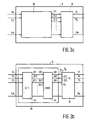
- Figure 3a shows a more detailed description of the arrangement in accordance with the invention, which is included in the block 6 of figure 1.
- the block 6 comprises a calculation unit 20 for each time determining from the M subband signals, information which is representative of the signal spectrum of the wideband digital audio signal applied to the terminal 1.
- the calculation unit 20 has M inputs coupled to the M inputs 5.1 to 5.M of the block 6 so as to receive the M subband signals.
- the information representative of the signal spectrum of the wideband digital audio signal is available at a number of outputs indicated 21.1, 21.2, 21.3, ... and so on. Those outputs are coupled to corresponding inputs of a further processing unit 32.
- the information available at the outputs of the unit 20 can be in the form of the M values v 1 to v M , v m being the signal power or energy of the signal portion or signal block of the subband signal SB m in subband m.
- the powers v m thus obtained are supplied to the further processing unit 32, which carries out a matrix manipulation, as described in the documents (D1) and (D2) so as to obtain the bitneeds b 1 to b M .
- the calculation unit 20 is adapted to carry out a discrete Fourier transform based signal processing on each of the subband signals.
- the said Fourier transform based signal processing is equivalent to carrying out on each of the subband signals, more specifically each of the corresponding time equivalent signal blocks of the subband signals, a discrete Fourier transform (DFT) so as to obtain a set of Fourier transform coefficients for each one of said subband signals, deriving information representative of the signal spectrum in a subband and combining the sets of information so as to obtain the information representative of the signal spectrum of the wideband digital audio signal.
- the information representative of the signal spectrum in a subband can be in the form of a set of power values for corresponding frequencies in said subband.
- the said M sets of power values are combined so as to obtain a combined set of power values representing the signal spectrum of the wideband digital audio signal.
- the Fourier transform based signal processing is equivalent to n times carrying out a discrete Fourier transform, such as a fast Fourier transform, on each of the time equivalent signal blocks of the subband signals.
- a discrete Fourier transform such as a fast Fourier transform
- those signal portions in a signal block of a subband signal on which two subsequent Fourier transforms are carried out may in time partly overlap.
- Each Fourier transform carried out on a signal block results in a set of Fourier coefficients from which a set of power values representing the signal spectrum in the subband can be derived.
- n sets of such power values are obtained for each subband.
- Those n sets of power values are combined so as to obtain one combined set of power values for each subband.
- the M sets of combined set of power values are combined so as to obtain a set of power values representing the signal spectrum of the wideband digital audio signal.
- the Fourier transform based signal processing is 'equivalent to' carrying out a Fourier transform on a signal portion so as to obtain Fourier transform coefficients and deriving therefrom power values, means that the signal processing need not actually carry out said subsequent steps of carrying out a Fourier transform, obtaining the Fourier transform coefficients and deriving therefrom the power values.
- the actual signal processing carried out is 'based on' said steps. Otherwise said, the signal processing carried out is based on a calculation in which all those steps are subsequently carried out, but where the signal processing only includes the resulting calculation, so that the separate steps on which the calculation is based is not visible anymore in the signal processing carried out. This will be explained by further working out the second embodiment.
- This second embodiment can be realized by the circuit block diagram of figure 3b, which shows the calculation unit 20 comprising a transformation unit 22, which generates the M sets of power values (one set for each subband) at outputs 26.1, 26.2, 26.3, ... and so on.
- Those M sets of power values are supplied to a combining unit 24, to combine the M sets of power values so as to obtain one combined set of power values representing the signal spectrum of the wideband digital audio signal.
- the samples x[0] to x[3] are in the first one of the three fourier transforms carried out on a signal block equal to the samples s 1 to s 4 respectively.
- the samples x[0] to x[3] are in the second one of the three fourier transforms carried out on a signal block equal to the samples s 5 to s 8 respectively.
- the samples x[0] to x[3] are in the third one of the three fourier transforms carried out on a signal block equal to the samples s 9 to s 12 respectively.
- the fourier transform can be written as:
- 2 (x[0]+x[1]+x[2]+x[3]) 2 .
- 2 2 ⁇ (x[0]-x[2]) 2 + (x[1]-x[3]) 2 ⁇ .
- 2 (x[0]-x[1]+x[2]-x[3]) 2 .
- the computation explained above is carried out three times for each subband, namely on the first four samples of a signal block, the second four samples in the said signal block and on the third four samples in the signal block.
- three sets of powers P(0,m), P(1,m) and P(2,m) are obtained.
- the three values P(0,m) are added so as to obtain the power P(0,m) used for the further processing.
- the three values P(1,m) are added so as to obtain the power P(1,m) used for the further processing.
- the three values P(2,m) are added so as to obtain the power P(2,m) used for the further processing.
- Another combination could be to realize some weighting on the three values for each of the P(0,m), P(1,m) and P(2,m).
- the three power values thus obtained for each subband are supplied to the outputs 26.1, 26.2, 26.3, .... and so on of the transformation unit 22.
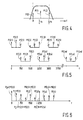
- the value f s /2 equals 750 Hz. This for the reason that the wideband digital audio signal can have a frequency of 24 kHz, which results in a sampling frequency of 48 kHz, in accordance with the Nyquist sampling theorem. As M is 32, this results in 750 Hz (24000/32) wide subbands.
- P(0,1) for this subband thus relates to the actual power of the wideband digital audio signal at a frequency of 0 Hz
- P(2,1) for this subband thus relates to the actual power of the wideband digital audio signal at a frequency of 750 Hz.
- the frequency value f s /4 relates to the central frequency of the subband from 750 to 1500 Hz, that is 1125 Hz.
- the subband from 750 Hz and 1500 Hz not only has been mixed down to the frequency band between 0 Hz and 750 Hz, but has also been mirrored around the central frequency of the subband.
- the power P(0,2) obtained as given above now has a relation to the power of the wideband digital audio signal at a frequency of 1500 Hz
- the power P(1,2) relates to the actual power of the wideband digital audio signal at a frequency of 1125 Hz
- this subband runs from 1500 Hz to 2250 Hz.
- P(0,3) for this subband thus relates to the actual power of the wideband digital audio signal at a frequency of 1500 Hz
- P(1,3) for this subband thus relates to the actual power of the wideband digital audio signal at a frequency of 1875 Hz
- P(2,3) for this subband thus relates to the actual power of the wideband digital audio signal at a frequency of 2250 Hz.
- this subband runs from 2250 Hz to 3000 Hz.
- P(0,4) for this subband thus relates to the actual power of the wideband digital audio signal at a frequency of 3000 Hz
- P(1,4) for this subband thus relates to the actual power of the wideband digital audio signal at a frequency of 2250 Hz
- P(2,4) for this subband thus relates to the actual power of the wideband digital audio signal at a frequency of 2625 Hz.
- Figure 5 shows the results for the various subbands, as a function of frequency, present at the outputs of the transformation unit 22.
- the top line of power spectra are the power spectra for the subbands with odd sequence numbers, running from 1 and up, and the lower line of power spectra are the power spectra for the subbands with the even sequence numbers.
- bitneeds b 1 to b M Another way of obtaining the bitneeds is as follows. From document (D2) it is known that only 32 values for v m , as power values for the subsequent matrix manipulation are needed so as to obtain the bitneeds b 1 to b M . Consequently, in order to use the well known matrix manipulation as a way to obtain the bitneeds b 1 to b M , it will be necessary to convert the 65 power values P j of figure 6 into only 32 power values that can be used as the values v m in the well known bitneed calculation method described in (D2).
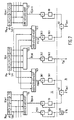
- Figure 7 shows schematically an embodiment of the calculation unit 20 for carrying out the signal processing described above.
- the calculation unit 20 comprises the transformation unit 22 and the signal combining unit 24 of figure 3b.
- the transformation unit 22 comprises memories 50.1 to 50.q, of which only the memories 50.m-1, 50.m and 50.m+1 are shown.
- the memories have four storage locations for storing four subsequent sample values indicated x[0] to x[3].
- the memories 50.1 to 50.M have inputs coupled to the inputs 5.1 to 5. M of the bit determining unit 6 for receiving the subband signals. Only the inputs 5.m-1, 5.m and m+1 are shown in figure 7.
- the memory 50.m-1 stores each time four sample values of the subband signal SB m-1 . As has been said previously, those four sample values can be the sample values s 1 to s 4 , or the sample values s 5 to s 8 or the sample values s 9 to s 12 of a signal block of the subband signal SB m-1 .
- the memory 50.m stores each time four sample values of the subband signal SB m .
- the four sample values stored in the memory 50.m are time equivalent to the samples stored in the memory 50.m-1.
- the memory 50.m+1 stores each time four sample values of the subband signal SB m+1 .
- the four sample values stored in the memory 50.m+1 are time equivalent to the four samples stored in the memories 50.m-1 and 50.m.
- the calculation block 52.1 is adapted to calculate the power P(0,m) from the four sample values x[0] to x[3] in accordance with the equation given above.
- the calculation block 52.2 is adapted to calculate the power P(1,m) from the four sample values x[0] to x[3] in accordance with the equation given above.
- the calculation block 52.3 is adapted to calculate the power P(2,m) from the four sample values x[0] to x[3] in accordance with the equation given above.
- Figure 7 shows the calculation block 53 for calculating the power P(2,m+1) from the sample values x[0] to x[3] stored in the memory 50.m+1, and the calculation block 54 for calculating the power P(0,m-1) from the sample values x[0] to x[3] stored in the memory 50.m-1.
- the outputs of all calculation blocks are coupled to a first input of an adder unit, such as the adder units 56.1, 56.2 and 56.3.
- An output of the adder units is coupled to an input of a memory, such as the memories 58.1, 58.2 and 58.3.
- Outputs of the memories are coupled to a second input of the adder units.
- the outputs of the memories 59 and 58.1 are further coupled to corresponding inputs of an adder unit 62 and the outputs of the memories 58.3 and 60 are coupled to corresponding inputs of an adder unit 63.
- the signal processing on time equivalent signal blocks is as follows.
- the memories 58.1, 58.2, 58.3, 59 and 60 are cleared so that their contents is zero.
- the first four sample values s 1 to s 4 of all the time equivalent signal blocks of the M subband signals are stored in the memories 50.1 to 50.M.
- the three power values P(0,m), P(1.m) and P(2,m) are calculated in the calculation blocks 52.1, 52.2 and 52.3.
- the contents of the memories 58.1, 58.2 and 58.3 are zero, a zero value is supplied to the second inputs of the adders. Consequently, the power values are stored in the memories 58.1, 58.2 and 58.3 as they are.
- the second set of four sample values s 5 to s 8 of all the time equivalent signal blocks are stored in the memories 50.1 to 50.M.
- the three power values P(0,m), P(1,m) and P(2,m) for a subband signal SB m are calculated and supplied to the respective adders 56.1, 56.2 and 56.3.
- the power values now calculated are added to the power values stored in the memories 58.1, 58.2 and 58.3 and the added values are again stored in the said memories.
- the third set of four sample values s 9 to s 12 of all the time equivalent signal blocks are stored in the memories 50.1 to 50.M.
- the three power values P(0,m), P(1,m) and P(2,m) for a subband signal SB m are calculated and supplied to the respective adders 56.1, 56.2 and 56.3.
- the power values now calculated are added to the power values stored in the memories 58.1, 58.2 and 58.3 and the added values are again stored in the said memories.
- the power value now stored in the memory 58.2 is the power value P 2m , see above. Further, the power values P(0,m-1) and P(0,m) stored in the memories 59 and 58.1 respectively are added together in the adder unit 62 so as to obtain the power value P 2m-1 , see also above. In the same way, the power values P(2,m) and P(2,m+1) stored in the memories 58.3 and 60 respectively are added together in the adder unit 63 so as to obtain the power value P 2m+1 , see also above.
- the signal combination unit 24 thus comprises a number of adder units, such as the adder units 62 and 63 shown in figure 7, for adding each time the power value for the lowest frequency in a subband with the power value for the highest frequency in the next lower subband.
- the multiplier 65 has its input coupled to the output of the memory 64, in which the power value P(0,1) is stored.
- the multiplier 65 multiplies P(0,1) by 2 so as to obtain P 0 .
- a windowing such as a Hamming windowing, is carried out on the signals prior to carrying out the time-to-frequency transform based processing.
- an aliasing compensation well known in the art is preferably carried out in the case when p 1 is larger than 4.
Landscapes
- Engineering & Computer Science (AREA)
- Computer Networks & Wireless Communication (AREA)
- Signal Processing (AREA)
- Compression, Expansion, Code Conversion, And Decoders (AREA)
- Transmission Systems Not Characterized By The Medium Used For Transmission (AREA)
- Reduction Or Emphasis Of Bandwidth Of Signals (AREA)
Claims (11)
- Adaptives Bitzuordnungesystem mit einer Einrichtung zum Ermitteln eines Signalspektrums eines digitalen Breitband-Audiosignals und zum in Reaktion darauf Herleiten von Bitzuordnungsinformation in einem adaptiven Bitzuordnungssystem, wobei diese Einrichtung die nachfolgenden Elemente umfasst:eine Eingangsklemme (1) zum Empfangen des digitalen Breitband-Audiosignals,Signalspaltmittel (2) zum Aufteilen des digitalen Breitband-Audiosignals in M schmalbandige Teilsignale, wobei jedes Signale der M Teilsignals repräsentativ ist für einen Anteil des digitalen Breitband-Audiosignals, das vorhanden ist in einem entsprechenden Band von M benachbarten im Wesentlichen nicht überlappenden schmalen Bändern in dem Frequenzband des digitalen Breitband-Audiosignals,Rechenmittel (6) zum jeweiligen Ermitteln von Information aus den M Teilsignalen, wobei diese Information repräsentativ ist für das Signalspektrum des digitalen Breitband-Audiosignals,Mittel (7) zum Ermitteln von Bitzuordnungsinformation zum Herleiten von Bitzuordnungsinfomation in Reaktion auf die Information, die repräsentativ ist für das Signalspektrum des digitalen Breitband-Audiosignals, wobei die Bitzuordnungsinformation repräsentativ ist für die Anzahl Bits, mit denen Abtastwerte der Teilsignale dargestellt werden, und wobei M eine ganze Zahl ist, größer als Eins, dadurch gekennzeichnet, dass die Rechenmittel (6) Transformationsmittel (20) umfassen um an jedem der Teilsignale eine Signalverarbeitung auf Basis einer eine Zeit-zu-Frequenztransformation durchzuführen zum Erhalten der genannten Information, die repräsentativ ist für das Signalspektrum des digitalen Breitband-Audiosignals.
- Bitzuordnungssystem nach Anspruch 1, wobei die Rechenmittel dazu vorgesehen sind, jeweils aus M zeitgleichen Signalblöcken einen Block in jedem der M Teilsignale zu ermitteln, wobei jeder Signalblock q1 Abtastwerte eines Teilsignals enthält, die genannte Information zu ermitteln, die repräsentativ ist für das Signalspektrum des digitalen Breitband-Audiosignals, wobei q1 eine ganze Zahl größer als Eins ist, dadurch gekennzeichnet, dass die Transformationsmittel weiterhin dazu vorgesehen sind, an jedem der zeitgleichen Signalblöcke eine Signalverarbeitung auf Basis der Zeit-zu-Frequenztransformation durchzuführen zum Erhalten der genannten Information, die für das Signalspektrum des digitalen Breitband-Audiosignals repräsentativ ist.
- Bitzuordnungssystem nach Anspruch 2, dadurch gekennzeichnet, dass die Transformationsmittel dazu vorgesehen sind, eine Signalverarbeitung auf Basis von Zeit-zu-Frequenztransformation durchzuführen, was gleichwertig ist mit der Durchführung einer Zeit-zu-Frequenztransformation an jedem Signalblock zum Erhalten von Transformationskoeffizienten für jeden Signalblock eines Teilbandsignals in einem Teilband, zu der Herleitung daraus von Information, die repräsentativ ist für das Signalspektrum in dem genannten Teilband, und zu der Kombination der Information, die repräsentativ ist für die Signalspektren in den M Teilbändern zum Erhalten der genannten Information, die repräsentativ ist für das Signalspektrum des digitalen Breitbandsignals.
- Bitzuordnungssystem nach Anspruch 2, dadurch gekennzeichnet, dass die Transformationsmittel dazu vorgesehen sind, eine Signalverarbeitung auf Basis einer Zeit-zu-Frequenztransformation durchzuführen, die gleichwertig ist mit der Durchführung, an jedem Signalblock, einer n-fachen Zeit-zu-Frequenztransformation an Abtastwerten eines Signalblocks zum Erhalten von n Sätzen von Transformationskoeffizienten für einen Signalblock in einem Teilband, zu der Herleitung daraus von Information, die repräsentativ ist für das Signalspektrum in dem genannten Teilband, und zu der Kombination der Information, die repräsentativ ist für die Signalspektren in den M Teilbändern zum Erhalten der genannten Information, die repräsentativ ist für das Signalspektrum des digitalen Breitband-Audiosignals.
- Bitzuordnungssystem nach Anspruch 3 oder 4, dadurch gekennzeichnet, dass die genannte Information, die repräsentativ ist für das Signalspektrum in einem Teilband, in Form einer Anzahl Leistungswerte für eine entsprechende Anzahl Frequenzen in dem genannten Teilband ist, wobei die Transformationsmittel weiterhin dazu vorgesehen sind, die M Sätze mit Leistungswerten zu kombinieren, einen Satz für jedes Teilband, zum Erhalten eines kombinierten Satzes mit Leistungswerten, der das Signalspektrum des digitalen Breitband-Audiosignals darstellt.
- Bitzuordnungssystem nach Anspruch 4, dadurch gekennzeichnet, dass die Transformationsmittel dazu vorgesehen sind, eine Signalverarbeitung auf Basis einer Zeit-zu-Frequenztransformation durchzuführen, die gleichwertig ist mit der Durchführung an jedem Signalblock in einem Teilband einer n-fachen Zeit-zu-Frequenztransformation an p1 Abtastwerten in einem Signalblock zum Erhalten von n Sätzen mit Transformationskoeffizienten, mit der Herleitung einer Anzahl von p2 Leistungswerten für eine entsprechende Anzahl von p2 Frequenzen in dem genannten Teilband aus diesen n Sätzen mit Transformationskoeffizienten, wobei die Transformationsmittel weiterhin dazu vorgesehen sind, die M Sätze mit p2 Leistungswerten zu kombinieren, damit ein kombinierter Satz von p3 Leistungswerten erhalten wird, der das Signalspektrum des digitalen Breitband-Audiosignals darstellt, wobei n, p1, p2 und p3 ganze Zahlen größer als 1 sind und wobei p1 kleiner ist als q1.
- Bitzuordnungssystem nach Anspruch 6, dadurch gekennzeichnet, dass n = q1/p1 ist.
- Bitzuordnungssystem nach Anspruch 5 oder 6, dadurch gekennzeichnet, dass die Transformationsmittel weiterhin dazu vorgesehen sind, den Leistungswert des Satzes mit Leistungswerten entsprechend dem höchsten Frequenzanteil in einem Teilband mit dem Leistungswert des Satzes mit Leistungswerten entsprechend dem niedrigsten Frequenzanteil in dem nächst höheren Teilband zu kombinieren.
- Bitzuordnungssystem nach Anspruch 8, insofern abhängig von Anspruch 6, dadurch gekennzeichnet, dass p3 = M(p2-1)+1 ist.
- Bitzuordnungssystem nach Anspruch 6, dadurch gekennzeichnet, dass q1 = 12 und p1 = 4 ist.
- Bitzuordnungssystem nach einem der vorstehenden Ansprüche, dadurch gekennzeichnet, dass eine Zeit-zu-Frequenztransformation eine diskrete Fourier Transformation ist.
Priority Applications (1)
| Application Number | Priority Date | Filing Date | Title |
|---|---|---|---|
| EP95915999A EP0707761B1 (de) | 1994-05-19 | 1995-05-10 | Vorrichtung zur bestimmung des signalspektrums eines digitalen breitbandsignals und zur ableitung einer bitzuweisungsinformation |
Applications Claiming Priority (4)
| Application Number | Priority Date | Filing Date | Title |
|---|---|---|---|
| EP94201427 | 1994-05-19 | ||
| EP94201427 | 1994-05-19 | ||
| EP95915999A EP0707761B1 (de) | 1994-05-19 | 1995-05-10 | Vorrichtung zur bestimmung des signalspektrums eines digitalen breitbandsignals und zur ableitung einer bitzuweisungsinformation |
| PCT/IB1995/000348 WO1995032556A1 (en) | 1994-05-19 | 1995-05-10 | Arrangement for determining a signal spectrum of a wideband digital signal and for deriving bit allocation information in response thereto |
Publications (2)
| Publication Number | Publication Date |
|---|---|
| EP0707761A1 EP0707761A1 (de) | 1996-04-24 |
| EP0707761B1 true EP0707761B1 (de) | 2001-09-26 |
Family
ID=8216890
Family Applications (1)
| Application Number | Title | Priority Date | Filing Date |
|---|---|---|---|
| EP95915999A Expired - Lifetime EP0707761B1 (de) | 1994-05-19 | 1995-05-10 | Vorrichtung zur bestimmung des signalspektrums eines digitalen breitbandsignals und zur ableitung einer bitzuweisungsinformation |
Country Status (5)
| Country | Link |
|---|---|
| US (1) | US5784533A (de) |
| EP (1) | EP0707761B1 (de) |
| JP (1) | JP3830106B2 (de) |
| DE (1) | DE69522883T2 (de) |
| WO (1) | WO1995032556A1 (de) |
Families Citing this family (2)
| Publication number | Priority date | Publication date | Assignee | Title |
|---|---|---|---|---|
| KR100261254B1 (ko) * | 1997-04-02 | 2000-07-01 | 윤종용 | 비트율 조절이 가능한 오디오 데이터 부호화/복호화방법 및 장치 |
| US5903872A (en) * | 1997-10-17 | 1999-05-11 | Dolby Laboratories Licensing Corporation | Frame-based audio coding with additional filterbank to attenuate spectral splatter at frame boundaries |
Family Cites Families (11)
| Publication number | Priority date | Publication date | Assignee | Title |
|---|---|---|---|---|
| NL8700985A (nl) * | 1987-04-27 | 1988-11-16 | Philips Nv | Systeem voor sub-band codering van een digitaal audiosignaal. |
| US5222189A (en) * | 1989-01-27 | 1993-06-22 | Dolby Laboratories Licensing Corporation | Low time-delay transform coder, decoder, and encoder/decoder for high-quality audio |
| NL9000338A (nl) * | 1989-06-02 | 1991-01-02 | Koninkl Philips Electronics Nv | Digitaal transmissiesysteem, zender en ontvanger te gebruiken in het transmissiesysteem en registratiedrager verkregen met de zender in de vorm van een optekeninrichting. |
| EP0400222A1 (de) * | 1989-06-02 | 1990-12-05 | ETAT FRANCAIS représenté par le Ministère des Postes, des Télécommunications et de l'Espace | Digitales Übertragungssystem unter Verwendung der Teilbandkodierung eines digitalen Signals |
| US5150387A (en) * | 1989-12-21 | 1992-09-22 | Kabushiki Kaisha Toshiba | Variable rate encoding and communicating apparatus |
| NL9001127A (nl) * | 1990-05-14 | 1991-12-02 | Philips Nv | Kodeerinrichting bevattende een subbandkoder, en een zender voorzien van de kodeerinrichting. |
| US5367608A (en) * | 1990-05-14 | 1994-11-22 | U.S. Philips Corporation | Transmitter, encoding system and method employing use of a bit allocation unit for subband coding a digital signal |
| NL9001128A (nl) * | 1990-05-14 | 1991-12-02 | Philips Nv | Kodeerinrichting bevattende een subbandkoder, en een zender voorzien van de kodeerinrichting. |
| JP3033156B2 (ja) * | 1990-08-24 | 2000-04-17 | ソニー株式会社 | ディジタル信号符号化装置 |
| US5365553A (en) * | 1990-11-30 | 1994-11-15 | U.S. Philips Corporation | Transmitter, encoding system and method employing use of a bit need determiner for subband coding a digital signal |
| US5583962A (en) * | 1991-01-08 | 1996-12-10 | Dolby Laboratories Licensing Corporation | Encoder/decoder for multidimensional sound fields |
-
1995
- 1995-05-10 JP JP53016795A patent/JP3830106B2/ja not_active Expired - Lifetime
- 1995-05-10 DE DE69522883T patent/DE69522883T2/de not_active Expired - Fee Related
- 1995-05-10 EP EP95915999A patent/EP0707761B1/de not_active Expired - Lifetime
- 1995-05-10 WO PCT/IB1995/000348 patent/WO1995032556A1/en not_active Ceased
- 1995-05-17 US US08/442,847 patent/US5784533A/en not_active Expired - Lifetime
Also Published As
| Publication number | Publication date |
|---|---|
| EP0707761A1 (de) | 1996-04-24 |
| WO1995032556A1 (en) | 1995-11-30 |
| DE69522883T2 (de) | 2002-04-11 |
| DE69522883D1 (de) | 2001-10-31 |
| JPH09501037A (ja) | 1997-01-28 |
| US5784533A (en) | 1998-07-21 |
| JP3830106B2 (ja) | 2006-10-04 |
Similar Documents
| Publication | Publication Date | Title |
|---|---|---|
| JP4242450B2 (ja) | フェーザ測定用単一側波帯フィルタバンクの効率的実施装置 | |
| US5294925A (en) | Data compressing and expanding apparatus with time domain and frequency domain block floating | |
| CA2166551C (en) | Computationally efficient adaptive bit allocation for coding method and apparatus | |
| KR100253136B1 (ko) | 저계산 복잡도의 디지탈 필터뱅크 | |
| US8606587B2 (en) | Method for reduction of aliasing introduced by spectral envelope adjustment in real-valued filterbanks | |
| JP2821713B2 (ja) | 高品質オーディオ用低ビット伝送速度変換コーダ、デコーダ、及びエンコーダ・デコーダ | |
| US8155954B2 (en) | Device and method for generating a complex spectral representation of a discrete-time signal | |
| EP0799531B1 (de) | Verfahren und gerät zum anwenden von wellenformprädiktion auf teilbänder in einem perzeptiven kodiersystem | |
| EP0473367B1 (de) | Digitaler Signalverschlüssler | |
| EP0610975A2 (de) | Formatierung eines kodierten Signals für Kodierer und Dekodierer eines Audiosystems hoher Qualität | |
| EP0599315A2 (de) | Vorrichtung und Verfahren zur Orthogonaltransformation eines digitalen Informationssignals mit Massstabverkleinerung zur Überlaufsverhinderung | |
| JPH07210195A (ja) | 高品質ディジタル・オーディオの効率的な圧縮のための方法および装置 | |
| PL174314B1 (pl) | Sposób i urządzenie do dekodowania sygnałów cyfrowych | |
| US9225318B2 (en) | Sub-band processing complexity reduction | |
| EP0697665B1 (de) | Verfahren und Vorrichtung zur Kodierung, Übertragung und Dekodierung von Information | |
| EP0693829A1 (de) | Verfahren und vorrichtung zum kodieren und dekodieren von informationen | |
| WO2002091588A1 (en) | Sub-band adaptive differential pulse code modulation/encoding apparatus, sub-band adaptive differential pulse code modulation/encoding method, wireless transmission system, sub-band adaptive differential pulse code modulation/decoding apparatus, sub-band adaptive differential pulse code modulation/decoding method, and wirel | |
| EP0775389B1 (de) | Einrichtung und verfahren zum kodieren eines digitalen signals mit mindestens einer ersten und einer zweiten digitalen signalkomponente | |
| US5784533A (en) | Arrangement for determining a signal spectrum of a wideband digital signal and for deriving bit allocation information in response thereto | |
| US6064698A (en) | Method and apparatus for coding | |
| EP2755205B1 (de) | Subband-Verarbeitung zur Komplexitätsverringerung | |
| JPH09102742A (ja) | 符号化方法および装置、復号化方法および装置、並びに記録媒体 | |
| JP3093178B2 (ja) | 高品質オーディオ用低ビットレート変換エンコーダ及びデコーダ | |
| JP4114244B2 (ja) | エンコード方法、デコード方法、エンコード装置、デコード装置、ディジタル信号記録方法、ディジタル信号記録装置、ディジタル信号送信方法及びディジタル信号送信装置 | |
| JP3513879B2 (ja) | 情報符号化方法及び情報復号化方法 |
Legal Events
| Date | Code | Title | Description |
|---|---|---|---|
| PUAI | Public reference made under article 153(3) epc to a published international application that has entered the european phase |
Free format text: ORIGINAL CODE: 0009012 |
|
| AK | Designated contracting states |
Kind code of ref document: A1 Designated state(s): DE FR GB |
|
| 17P | Request for examination filed |
Effective date: 19960530 |
|
| RAP3 | Party data changed (applicant data changed or rights of an application transferred) |
Owner name: KONINKLIJKE PHILIPS ELECTRONICS N.V. |
|
| GRAG | Despatch of communication of intention to grant |
Free format text: ORIGINAL CODE: EPIDOS AGRA |
|
| 17Q | First examination report despatched |
Effective date: 20001207 |
|
| GRAG | Despatch of communication of intention to grant |
Free format text: ORIGINAL CODE: EPIDOS AGRA |
|
| GRAH | Despatch of communication of intention to grant a patent |
Free format text: ORIGINAL CODE: EPIDOS IGRA |
|
| GRAH | Despatch of communication of intention to grant a patent |
Free format text: ORIGINAL CODE: EPIDOS IGRA |
|
| GRAA | (expected) grant |
Free format text: ORIGINAL CODE: 0009210 |
|
| AK | Designated contracting states |
Kind code of ref document: B1 Designated state(s): DE FR GB |
|
| REF | Corresponds to: |
Ref document number: 69522883 Country of ref document: DE Date of ref document: 20011031 |
|
| REG | Reference to a national code |
Ref country code: GB Ref legal event code: IF02 |
|
| ET | Fr: translation filed | ||
| PLBE | No opposition filed within time limit |
Free format text: ORIGINAL CODE: 0009261 |
|
| STAA | Information on the status of an ep patent application or granted ep patent |
Free format text: STATUS: NO OPPOSITION FILED WITHIN TIME LIMIT |
|
| 26N | No opposition filed | ||
| PGFP | Annual fee paid to national office [announced via postgrant information from national office to epo] |
Ref country code: GB Payment date: 20060525 Year of fee payment: 12 |
|
| PGFP | Annual fee paid to national office [announced via postgrant information from national office to epo] |
Ref country code: FR Payment date: 20060530 Year of fee payment: 12 |
|
| PGFP | Annual fee paid to national office [announced via postgrant information from national office to epo] |
Ref country code: DE Payment date: 20060714 Year of fee payment: 12 |
|
| GBPC | Gb: european patent ceased through non-payment of renewal fee |
Effective date: 20070510 |
|
| REG | Reference to a national code |
Ref country code: FR Ref legal event code: ST Effective date: 20080131 |
|
| PG25 | Lapsed in a contracting state [announced via postgrant information from national office to epo] |
Ref country code: DE Free format text: LAPSE BECAUSE OF NON-PAYMENT OF DUE FEES Effective date: 20071201 |
|
| PG25 | Lapsed in a contracting state [announced via postgrant information from national office to epo] |
Ref country code: GB Free format text: LAPSE BECAUSE OF NON-PAYMENT OF DUE FEES Effective date: 20070510 |
|
| PG25 | Lapsed in a contracting state [announced via postgrant information from national office to epo] |
Ref country code: FR Free format text: LAPSE BECAUSE OF NON-PAYMENT OF DUE FEES Effective date: 20070531 |