EP0707897A1 - Verfahren zur regulierung der adhesion beim abstreifen mittels gas - Google Patents
Verfahren zur regulierung der adhesion beim abstreifen mittels gas Download PDFInfo
- Publication number
- EP0707897A1 EP0707897A1 EP93911942A EP93911942A EP0707897A1 EP 0707897 A1 EP0707897 A1 EP 0707897A1 EP 93911942 A EP93911942 A EP 93911942A EP 93911942 A EP93911942 A EP 93911942A EP 0707897 A1 EP0707897 A1 EP 0707897A1
- Authority
- EP
- European Patent Office
- Prior art keywords
- strip
- nozzle
- coating weight
- wiping
- coating
- Prior art date
- Legal status (The legal status is an assumption and is not a legal conclusion. Google has not performed a legal analysis and makes no representation as to the accuracy of the status listed.)
- Granted
Links
- 238000000034 method Methods 0.000 title claims description 34
- 239000011248 coating agent Substances 0.000 claims abstract description 193
- 238000000576 coating method Methods 0.000 claims abstract description 193
- 239000002184 metal Substances 0.000 claims abstract description 69
- 229910052751 metal Inorganic materials 0.000 claims abstract description 69
- 239000000463 material Substances 0.000 claims abstract description 38
- 239000003973 paint Substances 0.000 claims description 49
- 230000001105 regulatory effect Effects 0.000 abstract 1
- 238000007747 plating Methods 0.000 description 55
- 238000002347 injection Methods 0.000 description 10
- 239000007924 injection Substances 0.000 description 10
- 238000010586 diagram Methods 0.000 description 9
- 238000010422 painting Methods 0.000 description 7
- 230000000704 physical effect Effects 0.000 description 6
- 238000007654 immersion Methods 0.000 description 5
- 238000004458 analytical method Methods 0.000 description 4
- 230000003247 decreasing effect Effects 0.000 description 4
- 238000009826 distribution Methods 0.000 description 4
- 230000005540 biological transmission Effects 0.000 description 3
- 238000002474 experimental method Methods 0.000 description 3
- 238000005246 galvanizing Methods 0.000 description 3
- 238000004519 manufacturing process Methods 0.000 description 3
- 238000007598 dipping method Methods 0.000 description 2
- 239000012530 fluid Substances 0.000 description 2
- 238000011835 investigation Methods 0.000 description 2
- 238000005259 measurement Methods 0.000 description 2
- 229910001335 Galvanized steel Inorganic materials 0.000 description 1
- 229910000831 Steel Inorganic materials 0.000 description 1
- HCHKCACWOHOZIP-UHFFFAOYSA-N Zinc Chemical compound [Zn] HCHKCACWOHOZIP-UHFFFAOYSA-N 0.000 description 1
- 230000001133 acceleration Effects 0.000 description 1
- 230000002411 adverse Effects 0.000 description 1
- 238000004364 calculation method Methods 0.000 description 1
- 238000005260 corrosion Methods 0.000 description 1
- 230000007797 corrosion Effects 0.000 description 1
- 238000001514 detection method Methods 0.000 description 1
- 230000002542 deteriorative effect Effects 0.000 description 1
- 239000008397 galvanized steel Substances 0.000 description 1
- 230000005484 gravity Effects 0.000 description 1
- 239000007788 liquid Substances 0.000 description 1
- 238000012986 modification Methods 0.000 description 1
- 230000004048 modification Effects 0.000 description 1
- 239000002904 solvent Substances 0.000 description 1
- 239000007921 spray Substances 0.000 description 1
- 239000010959 steel Substances 0.000 description 1
- 239000000126 substance Substances 0.000 description 1
- JBQYATWDVHIOAR-UHFFFAOYSA-N tellanylidenegermanium Chemical compound [Te]=[Ge] JBQYATWDVHIOAR-UHFFFAOYSA-N 0.000 description 1
- 230000000007 visual effect Effects 0.000 description 1
- XLYOFNOQVPJJNP-UHFFFAOYSA-N water Substances O XLYOFNOQVPJJNP-UHFFFAOYSA-N 0.000 description 1
- 238000004260 weight control Methods 0.000 description 1
- 239000011701 zinc Substances 0.000 description 1
- 229910052725 zinc Inorganic materials 0.000 description 1
Images


Classifications
-
- B—PERFORMING OPERATIONS; TRANSPORTING
- B05—SPRAYING OR ATOMISING IN GENERAL; APPLYING FLUENT MATERIALS TO SURFACES, IN GENERAL
- B05D—PROCESSES FOR APPLYING FLUENT MATERIALS TO SURFACES, IN GENERAL
- B05D3/00—Pretreatment of surfaces to which liquids or other fluent materials are to be applied; After-treatment of applied coatings, e.g. intermediate treating of an applied coating preparatory to subsequent applications of liquids or other fluent materials
- B05D3/04—Pretreatment of surfaces to which liquids or other fluent materials are to be applied; After-treatment of applied coatings, e.g. intermediate treating of an applied coating preparatory to subsequent applications of liquids or other fluent materials by exposure to gases
- B05D3/0406—Pretreatment of surfaces to which liquids or other fluent materials are to be applied; After-treatment of applied coatings, e.g. intermediate treating of an applied coating preparatory to subsequent applications of liquids or other fluent materials by exposure to gases the gas being air
- B05D3/042—Directing or stopping the fluid to be coated with air
-
- C—CHEMISTRY; METALLURGY
- C23—COATING METALLIC MATERIAL; COATING MATERIAL WITH METALLIC MATERIAL; CHEMICAL SURFACE TREATMENT; DIFFUSION TREATMENT OF METALLIC MATERIAL; COATING BY VACUUM EVAPORATION, BY SPUTTERING, BY ION IMPLANTATION OR BY CHEMICAL VAPOUR DEPOSITION, IN GENERAL; INHIBITING CORROSION OF METALLIC MATERIAL OR INCRUSTATION IN GENERAL
- C23C—COATING METALLIC MATERIAL; COATING MATERIAL WITH METALLIC MATERIAL; SURFACE TREATMENT OF METALLIC MATERIAL BY DIFFUSION INTO THE SURFACE, BY CHEMICAL CONVERSION OR SUBSTITUTION; COATING BY VACUUM EVAPORATION, BY SPUTTERING, BY ION IMPLANTATION OR BY CHEMICAL VAPOUR DEPOSITION, IN GENERAL
- C23C2/00—Hot-dipping or immersion processes for applying the coating material in the molten state without affecting the shape; Apparatus therefor
- C23C2/14—Removing excess of molten coatings; Controlling or regulating the coating thickness
- C23C2/16—Removing excess of molten coatings; Controlling or regulating the coating thickness using fluids under pressure, e.g. air knives
- C23C2/18—Removing excess of molten coatings from elongated material
- C23C2/20—Strips; Plates
Definitions
- the present invention relates to a method for adjusting coating weight by gas wiping and, more particularly, to a method for adjusting coating thickness by gas wiping excessive coating material with blows of gas injected from a wiping nozzle in the course of continuous coating of molten metal or paint to a strip.
- a so-called gas wiping is widely adopted in which an excessive amount of coating material such as a molten metal, paint, etc. is continuously coated on the surface of a strip and at the same time blows of gas are applied to the surface by use of a wiping nozzle to remove excessive coating material.
- the adjustment of the coating weight of a coating material on a continuous molten metal plating line and a painting line is subdivided into many types from the points of diversified purposes, corrosion resistance, and cost of products. Therefore, not only when the type of product is to be changed but when the target coating weight is to be changed, it is necessary to properly and rapidly change and set the nozzle injection pressure P, nozzle-strip distance D, slit clearance B of a wiping nozzle, strip velocity V, etc.
- a gas pressure on the surface of a strip is considered to be a function of a distance from a plating bath surface, and nozzle height, nozzle-strip distance, and gas injection pressure are adjusted to satisfy the function;
- the coating weight of plating is adjusted by utilizing the gas injection pressure expressed as the function of the distance, height and angle of nozzle, line speed, and coating weight of plating; and in Japanese Patent Laid-Open No.
- the coating weight of plating is adjusted by using a relational formula of a wiping pressure and coating weight and a relational formula of a nozzle distance and coating weight, at the time of feedback control of coating weight of plating immediately above the nozzle.
- the wiping nozzle injection pressure P and the nozzle-strip distance D are determined on the basis of the relational formula of the coating weight W of the coating material and operation factors in accordance with a target coating weight for the purpose of adjusting the coating weight of the coating material such as the molten metal, paint, etc. to be applied to a continuously moving strip. Therefore, in order to accurately adjust the coating weight of the coating material, it becomes important that the above-described relational formula to be used for control can properly and accurately express the wiping phenomenon of molten metal or paint throughout the range of operation.
- An error of the coating weight of the coating material from the target value resulting from inaccuracy of the relational formula appears as a steady-state deviation, not only in the feed-forward control but also in the feedback control, preventing high-accuracy adjustment of the coating weight of the coating material.
- the present invention has obviated the above disadvantages by adjusting the coating weight of a coating material applied to a strip, on the basis of the relational formula of coating weight which differs with a relation between the wiping nozzle slit clearance B and the nozzle-strip distance D with respect to a constant C, that is, between (i) D/B ⁇ C and (ii) D/B>C, when the coating weight of the coating material on the strip is adjusted by applying blows of gas, from the wiping nozzle disposed at the downstream side of a continuous coating apparatus for continuously coating the strip, against the strip coated by the continuous coating apparatus.
- the present invention has solved the above-described problems arising in the molten metal plating by the method for adjusting the coating weight of a coating material on a strip by gas wiping in which a wiping nozzle is disposed above a molten metal bath to apply blows of gas from the wiping nozzle against the strip that has passed through the molten metal bath, thereby adjusting the coating weight of molten metal on the strip on the basis of the relational formula of coating weight which differs with a relation between the wiping nozzle slit clearance B and the nozzle-strip distance D with respect to a constant C, that is, between (i) D/B ⁇ C and (ii) D/B>C.
- the present invention has solved the aforesaid problems arising in continuous painting by the method for adjusting the coating weight by gas wiping in which a wiping nozzle is disposed on the downstream side of a continuous painting apparatus to apply gas from the wiping nozzle against the strip that has passed through the continuous painting apparatus, thereby adjusting the coating weight of paint on the strip on the basis of the relational formula of coating weight which differs with a relation between the wiping nozzle slit clearance B and the nozzle-strip distance D with respect to a constant C, that is, between (i) D/B ⁇ C and (ii) D/B>C.
- the coating weight of a coating material on a strip is adjusted by a relational formula of coating weight exclusive of the slit clearance B in the case of (i) D/B ⁇ C and by a relational formula of coating weight inclusive of the slit clearance B in the case of (ii) D/B>C.
- the coating weight of a coating material on a strip is adjusted on the basis of a relational formula of coating weight while maintaining a relation of D/B ⁇ C by controlling at least one of the wiping nozzle slit clearance B and the nozzle-strip distance D.
- the present invention has been accomplished on the basis of information hereinafter described which the present inventor has acquired through varieties of investigations. The following description will be made primarily of molten metal plating using a molten metal as a coating material for convenience' sake.
- a first information obtained from a result of theoretical analysis of a molten metal wiping phenomenon by gas indicates that it is important to separately consider a relational formula of the coating weight and operation factors with a correlation between the wiping nozzle slit clearance B and the nozzle-strip distance D divided into the following two cases according to characteristics of gas jet from the wiping nozzle.
- a strip S is drawn upward after dipping through a plating bath 12 of molten metal contained in a plating tank 10, then blows of gas are applied at an injection pressure P against the surface of the strip S from wiping nozzles 14 at a level H above the plating bath 12 to wipe off excessive molten metal from the surface of the strip S.
- Fig. 3 schematically shows the wiping condition of the molten metal in the position of the wiping nozzle 14.
- the gas jet F is being applied at the pressure P from the wiping nozzle 14 against the strip S that has been drawn upward out of the plating bath 12 of molten metal
- the fluid behavior of the molten metal on the strip S can be expressed by the following equations (1) and (2) in a system of coordinates of the same drawing, by the use of an equation of motion and an equation of continuity in the fluid dynamics.
- equations (15) and (16) give only one example and the present invention should not be limited thereto; for example the constants and an exponent are changeable as occasion calls.
- the coating weight differs in the degree of influence of the operation factors between D/B ⁇ C and D/B>C; when B is changed, with D kept constant, the wiping efficiency rises (wiping becomes easier to perform) with a decrease in the ratio of D/B within the range of D/B>C. However, within the range of D/B ⁇ C, the wiping efficiency remains almost unchanged even when D/B has changed. This state is shown in Fig. 5. It is generally known that the wiping efficiency rises with the decrease of D.
- a third information indicates it important that, as a result of the aforesaid theoretical analyses plus further experiments and investigations, physical properties of the molten metal which have an influence upon wiping characteristics should be evaluated as a function of temperature of the molten metal in the wiping nozzle position.
- Fig. 6 which shows a relation between the plating metal (molten metal) temperature in the wiping nozzle position and a coating weight error (actually measured coating weight - calculated coating weight without the dependence of the plating metal temperature), the wiping characteristic lowers with the drop of the plating metal temperature. It has been found, however, that when the dependence of the plating temperature in the wiping nozzle position is taken into consideration, the error becomes very little.
- a strip S at a temperature T z.0 is dipped in a plating bath 12 at a temperature T M at a line speed V, then is drawn upward at a temperature T z.1 close to the plating bath temperature T M from the plating bath 12.
- the strip temperature T z.1 of the strip S going out of the plating bath 12 is given by the following equation (17), supposing that it is based on heat transmission to a flat plate under the molten metal.
- T Z.1 T M +(T Z.0 -T M ) ⁇ exp ⁇ -(2 ⁇ ⁇ M ⁇ 1 M ) /( ⁇ S ⁇ C p.s ⁇ t S ⁇ V) ⁇
- the temperature of the coating metal immediately after the strip is drawn upward out of the plating bath 12 is presumed as equal to the strip temperature T z.1 .
- the above-described two temperatures are substantially equal and accordingly there will occur no problem about the temperatures.
- the strip temperature and the coating metal temperature may be formulated as different ones.
- splash from the plating bath surface can be decreased by narrowing the slit clearance B.
- narrowing the slit clearance B as small as possible while controlling at least one of D and B within the range which satisfies D/B ⁇ C can decrease the wiping gas flow rate without deteriorating the wiping efficiency and further can reduce splash.
- Plating of a molten metal as a coating material has heretofore been described in detail.
- the present invention is similarly applicable to an optional continuous painting so far as the coating material is a liquid substance such as paint.
- the plating bath 12 in Figs. 2 and 3 is used as a continuous coating apparatus and the molten metal and the coating metal are replaced with paint and coating paint.
- a relation between the paint temperature in the wiping nozzle position and the paint coating weight error (an actual measured coating weight - a calculated coating weight without dependence of paint temperature taken into consideration), which corresponds to the relation shown in Fig. 6, is shown in Fig. 7.
- Fig. 8 is a block diagram showing a molten metal plating control apparatus applied to a first embodiment of the present invention.
- the control apparatus controls a continuous coating apparatus in such a manner that strip S which has been dipped through a plating bath 12 held in a plating tank 10 is drawn upward out of the plating bath 12, and is then moved. On both sides of the strip S that has been drawn upward out of the plating bath 12, a specific pressure gas is applied to both sides from wiping nozzles 14. The direction of travel of the strip S dipped in the plating bath 12 is changed by a sink roll 16.
- the wiping nozzle 14 is designed so that the nozzle distance D and the nozzle slit clearance B can be adjusted by means of an adjuster 18, and the nozzle height H is also adjustable by an adjuster 20.
- Ahead in the direction of travel of the strip S is disposed a film thickness meter 22 for measuring the film thickness in the direction of width.
- a detection signal from this film thickness meter 22 is entered into the adjuster 18 via a feedback characteristic compensator 24, a feedback control apparatus 26, and a control input selector 28.
- the length and speed of travel of the strip S are measured by means of a pulse oscillator 30 and a speed converter 32 provided at the measuring roll which rotates in contact with the strip S, and are inputted into the feedback characteristic compensator 24 and the feed-forward control apparatus 34.
- This feed-forward control apparatus 34 receives signals from a manufacturing condition setting device 36 and a preset control apparatus 38 respectively, to thereby control the pressure control valve 42 through a pressure regulator 40.
- the pressure control valve 42 enables the control of pressure of gas being emitted from the wiping nozzle.
- a signal from the manufacturing condition setting device 36 is inputted into the adjuster 18 through the preset control apparatus 38. Furthermore, a signal from the control input selector 28 is fed into the height adjuster 20.
- the feed-forward control when the operating conditions such as coating weight W, line speed V, and type of steel are changed, such set values as the nozzle-strip distance D, slit clearance B, and nozzle injection pressure P are determined by the use of the equation (15) or (16) according to the coating weight W and the line speed V.
- the nozzle-strip distance D should be set to the lower limit or higher so that the strip will not contact the nozzle, the injection pressure P will not exceed the upper limit, and the nozzle height H will be at a normal standard value.
- the nozzle-strip distance D, slit clearance B, and injection pressure P are adjusted to set values by the adjuster 18 and the pressure regulator 40.
- the nozzle height H, when requiring adjustment, is to be adjusted by the adjuster 20.
- the nozzle height H is set basically to the standard value.
- Fig. 1A shows a result of control of coating weight of plating with coating metal temperatures in the wiping position taken into consideration in the equations (15) and (16). Operating conditions at this time are given in Table 1.
- Fig. 1B shows a result of control of the coating weight of plating effected by a prior art method using the same control apparatus and a relational formula of the coating weight which is expressed by the following equation (21) prepared as a regression equation of operation factors.
- the nozzle slit clearances B is not taken into consideration and besides the physical properties of the molten zinc is also not taken into consideration.
- W k 1 ⁇ P C1 ⁇ V C2 ⁇ D C3
- the coating weight varies with the timing of change in the strip speed, target coating weight, and shape of strip, and that a deviation occurs even in a steady state in which no change arises in the operating conditions.
- the method of the present invention it is possible to control the coating weight nearly to the target coating weight regardless of various changes in the operating conditions.
- the adjustment of the coating weight of plating is made by controlling at least one of D and B within the developing range, that is, within the range satisfying D/B ⁇ C.
- Table 3 shows a result of hot-dip galvanizing carried out under the operating conditions shown in Table 2 given below, by the use of the same control apparatus as in the case of the first embodiment.
- Strip speed (m /min) 60 ⁇ 160 Strip thickness (mm ) 0.5 ⁇ 2.3 Strip width (mm ) 850 ⁇ 1800 Nozzle distance (mm ) 10 ⁇ 35 Target value of coating weight (g /m2 ) 30 ⁇ 120 Nozzle slit clearance (mm ) 0.6 ⁇ 2.3 (Prior art: 1.8) Nozzle-to-plating bath surface distance (mm ) 200 ⁇ 500
- Table 3 shows mean values; as compared with those in the prior art case, the wiping gas flow rate (gas consumption) can be reduced, the amount of splash can be decreased; and furthermore the nozzle pressure can be increased within the range not adversely affecting the plating operation (in the above table the wiping gas flow rate 1.0 corresponds to 5,500 Nm3/hr, and the limit nozzle pressure 1.0 corresponds to 0.65 kgG. The amount of splash is measured by visual observation.).
- the coating weight control range can be widened, enabling thin-coat plating even at a high line speed.
- the continuous coating control apparatus adopted in the present embodiment is substantially the same as the molten metal plating control apparatus used in the first embodiment except for the replacement of the plating tank 10 with the continuous coating apparatus and the plating bath 12 with an immersion paint bath in Fig. 8.
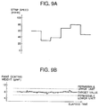
- Fig. 9B shows a result of control of the coating weight of paint obtained by using the equations (15) and (16), with the coated paint temperature in the wiping position taken into consideration, when the strip speed is changed as shown in Fig. 9A.
- the paint used is a water-soluble paint having the viscosity of 2 cP and the paint density of 1100 kg/m3.
- the paint temperature in the immersion bath 12 is 30 °C, and the strip temperature before immersion is 35 °C.
- the coated paint temperature at the wiping point varies with the strip speed: high at a high speed and low at a low speed.
- the paint temperature was 22 to 30 °C at this control time.
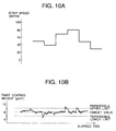
- Fig. 10 is a diagram corresponding to Fig. 9 which shows a result of control of the paint coating weight performed by a prior art method using the same control apparatus and a relational formula of the coating weight which is expressed by the following equation (22) prepared as a regression equation of operation factors.
- the prior art method is adopted to make this control, both the nozzle slit clearance B and the physical properties of the paint are not taken into consideration.
- W k 2 ⁇ P C4 ⁇ V C5 ⁇ D C6
- a relational formula (a control equation) to be used for controlling the coating weight of a coating material such as molten metal or paint is not limited to the equation (15) or (16) and changes may be made as desired so long as they control the coating weight of the coating material by a control equation exclusive of the nozzle slit clearance B in the range of D/B ⁇ C (developing range), and by a control equation inclusive of the nozzle-strip distance D and the slit clearance B in the range of D/B>C (fully developed range).
- the equation for evaluating the viscosity of the coating material as a function of temperature is not limited to the equation (19).
- molten metal plating control apparatus for actual use is not limited to that shown in the embodiment previously described, and also the type of plating is not limited to galvanizing.
- the continuous coating control apparatus is not limited to the device equipped with the immersion bath shown in the above-described embodiment as the continuous coating apparatus; for example, the apparatus may be changed as desired to one equipped with an apparatus such as a spray nozzle which can continuously apply the paint to the strip. Also the type of paint is not limited to that shown in the embodiment described above.
- the present invention it is possible to control the coating weight of the coating material to a target value even when a change is made in the operation factors owing to changes in the type of product and the shape of strip, by setting and using a relational formula for determining the coating weight of the coating material such as molten metal and paint on the basis of a relative relation between the nozzle-strip distance D and the nozzle slit clearance B.
Landscapes
- Chemical & Material Sciences (AREA)
- Chemical Kinetics & Catalysis (AREA)
- Engineering & Computer Science (AREA)
- Materials Engineering (AREA)
- Mechanical Engineering (AREA)
- Metallurgy (AREA)
- Organic Chemistry (AREA)
- Coating With Molten Metal (AREA)
- Coating By Spraying Or Casting (AREA)
- Application Of Or Painting With Fluid Materials (AREA)
Applications Claiming Priority (2)
| Application Number | Priority Date | Filing Date | Title |
|---|---|---|---|
| CA002139119A CA2139119C (en) | 1993-04-28 | 1993-04-28 | Method for adjusting coating weight by gas wiping |
| PCT/JP1993/000555 WO1994025179A1 (fr) | 1993-04-28 | 1993-04-28 | Procede utilisant la technique de l'essuyage par gaz pour reguler la quantite de placage adherant a un feuillard |
Publications (3)
| Publication Number | Publication Date |
|---|---|
| EP0707897A1 true EP0707897A1 (de) | 1996-04-24 |
| EP0707897A4 EP0707897A4 (de) | 1997-01-29 |
| EP0707897B1 EP0707897B1 (de) | 2001-01-03 |
Family
ID=25677707
Family Applications (1)
| Application Number | Title | Priority Date | Filing Date |
|---|---|---|---|
| EP93911942A Expired - Lifetime EP0707897B1 (de) | 1993-04-28 | 1993-04-28 | Verfahren zur regulierung der adhesion beim abstreifen mittels gas |
Country Status (7)
| Country | Link |
|---|---|
| US (1) | US5518772A (de) |
| EP (1) | EP0707897B1 (de) |
| CA (1) | CA2139119C (de) |
| DE (1) | DE69329831T2 (de) |
| ES (1) | ES2154646T3 (de) |
| FI (1) | FI108219B (de) |
| WO (1) | WO1994025179A1 (de) |
Cited By (5)
| Publication number | Priority date | Publication date | Assignee | Title |
|---|---|---|---|---|
| WO1999019528A1 (de) * | 1997-10-13 | 1999-04-22 | Siemens Aktiengesellschaft | Verfahren und einrichtung zum beschichten eines metallbandes |
| WO1999031949A3 (de) * | 1997-12-19 | 1999-08-26 | Siemens Ag | Verfahren und einrichtung zum beschichten eines metallbandes |
| WO2000066189A3 (en) * | 1999-05-03 | 2001-02-22 | Scimed Life Systems Inc | Medical device coating method and coated devices |
| EP2906734B1 (de) | 2013-03-06 | 2022-06-01 | Arcelormittal | Verfahren zur herstellung eines blechs mit einer znal-beschichtung und mit optimierter trocknung, entsprechendes blech, teil und fahrzeug |
| EP3205741B1 (de) * | 2014-10-08 | 2023-04-05 | JFE Steel Corporation | Kontinuierliches schmelztauchverfahren und ausrüstung für kontinuierliches schmelztauchverfahren |
Families Citing this family (10)
| Publication number | Priority date | Publication date | Assignee | Title |
|---|---|---|---|---|
| DE69628098T2 (de) * | 1995-02-24 | 2004-04-01 | Nisshin Steel Co., Ltd. | Heißtauchaluminiertes Blech, Verfahren für die Herstellung des Blechs und Legierungsschicht-Steuervorrichtung |
| US6582520B1 (en) | 1997-12-09 | 2003-06-24 | Ak Steel Corporation | Dross collecting zinc pot |
| DE19936148A1 (de) * | 1999-07-31 | 2001-02-01 | Abb Research Ltd | Verfahren zur Ermittlung von Sprühparametern für eine Lacksprühanlage |
| WO2007132701A1 (ja) * | 2006-05-12 | 2007-11-22 | Jfe Steel Corporation | 溶融金属めっき鋼帯の製造方法 |
| JP4347867B2 (ja) * | 2006-07-27 | 2009-10-21 | 株式会社日立製作所 | めっき付着量制御システムおよびめっき付着量制御方法 |
| JP5960174B2 (ja) * | 2014-02-10 | 2016-08-02 | Primetals Technologies Japan株式会社 | 溶融金属めっき付着量制御装置及び方法 |
| CN110352262B (zh) * | 2017-04-14 | 2021-04-20 | 普锐特冶金技术日本有限公司 | 镀敷附着量控制机构以及镀敷附着量控制方法 |
| EP3673091B1 (de) | 2017-08-22 | 2021-10-13 | ThyssenKrupp Steel Europe AG | Verwendung eines q und p-stahls zur herstellung einer geformten komponente für verschleissanwendungen |
| DE102017216572A1 (de) | 2017-09-19 | 2019-03-21 | Thyssenkrupp Ag | Schmelztauchbeschichtetes Stahlband mit verbessertem Oberflächenerscheinungsbild und Verfahren zu seiner Herstellung |
| EP3861146A1 (de) * | 2018-10-02 | 2021-08-11 | Tata Steel IJmuiden B.V. | Beschichtetes metallblech, verfahren zur bereitstellung solch eines beschichtetes metallblechs und feuerverzinkungsvorrichtung zur herstellung solch eines beschichteten metallblechs |
Family Cites Families (6)
| Publication number | Priority date | Publication date | Assignee | Title |
|---|---|---|---|---|
| US4078103A (en) * | 1975-04-17 | 1978-03-07 | Armco Steel Corporation | Method and apparatus for finishing molten metallic coatings |
| JPS54135628A (en) * | 1978-04-13 | 1979-10-22 | Nippon Kokan Kk <Nkk> | Continuous type hot dipping method |
| JPH0754952B2 (ja) * | 1986-12-15 | 1995-06-07 | 岩崎通信機株式会社 | 網接続制御装置 |
| JPS63149957U (de) * | 1987-03-23 | 1988-10-03 | ||
| JPH0633448B2 (ja) * | 1987-09-30 | 1994-05-02 | 住友金属工業株式会社 | 溶融金属メッキ付着量制御装置 |
| JPH03173756A (ja) * | 1989-11-30 | 1991-07-29 | Kawasaki Steel Corp | めっき付着量制御方法 |
-
1993
- 1993-04-28 DE DE69329831T patent/DE69329831T2/de not_active Expired - Fee Related
- 1993-04-28 ES ES93911942T patent/ES2154646T3/es not_active Expired - Lifetime
- 1993-04-28 US US08/351,377 patent/US5518772A/en not_active Expired - Fee Related
- 1993-04-28 CA CA002139119A patent/CA2139119C/en not_active Expired - Fee Related
- 1993-04-28 EP EP93911942A patent/EP0707897B1/de not_active Expired - Lifetime
- 1993-04-28 WO PCT/JP1993/000555 patent/WO1994025179A1/ja not_active Ceased
-
1994
- 1994-12-28 FI FI946124A patent/FI108219B/fi not_active IP Right Cessation
Non-Patent Citations (2)
| Title |
|---|
| No further relevant documents disclosed * |
| See also references of WO9425179A1 * |
Cited By (6)
| Publication number | Priority date | Publication date | Assignee | Title |
|---|---|---|---|---|
| WO1999019528A1 (de) * | 1997-10-13 | 1999-04-22 | Siemens Aktiengesellschaft | Verfahren und einrichtung zum beschichten eines metallbandes |
| WO1999031949A3 (de) * | 1997-12-19 | 1999-08-26 | Siemens Ag | Verfahren und einrichtung zum beschichten eines metallbandes |
| WO2000066189A3 (en) * | 1999-05-03 | 2001-02-22 | Scimed Life Systems Inc | Medical device coating method and coated devices |
| US6322847B1 (en) | 1999-05-03 | 2001-11-27 | Boston Scientific, Inc. | Medical device coating methods and devices |
| EP2906734B1 (de) | 2013-03-06 | 2022-06-01 | Arcelormittal | Verfahren zur herstellung eines blechs mit einer znal-beschichtung und mit optimierter trocknung, entsprechendes blech, teil und fahrzeug |
| EP3205741B1 (de) * | 2014-10-08 | 2023-04-05 | JFE Steel Corporation | Kontinuierliches schmelztauchverfahren und ausrüstung für kontinuierliches schmelztauchverfahren |
Also Published As
| Publication number | Publication date |
|---|---|
| FI946124A0 (fi) | 1994-12-28 |
| CA2139119C (en) | 2001-03-13 |
| ES2154646T3 (es) | 2001-04-16 |
| US5518772A (en) | 1996-05-21 |
| DE69329831T2 (de) | 2001-04-19 |
| CA2139119A1 (en) | 1994-11-10 |
| EP0707897B1 (de) | 2001-01-03 |
| FI108219B (fi) | 2001-12-14 |
| FI946124A7 (fi) | 1994-12-28 |
| WO1994025179A1 (fr) | 1994-11-10 |
| EP0707897A4 (de) | 1997-01-29 |
| DE69329831D1 (de) | 2001-02-08 |
Similar Documents
| Publication | Publication Date | Title |
|---|---|---|
| EP0707897A1 (de) | Verfahren zur regulierung der adhesion beim abstreifen mittels gas | |
| KR102099910B1 (ko) | 연속적인 두께-가변형 스트립 물질을 위한 용융 아연도금 층 두께 조절 시스템 및 방법 | |
| US3808033A (en) | Continuous metallic strip hot-dip metal coating apparatus | |
| US6199301B1 (en) | Coating thickness control | |
| US3459587A (en) | Method of controlling coating thickness | |
| US6185970B1 (en) | Method of and system for controlling a cooling line of a mill train | |
| US4529628A (en) | Method for the continuous coating of at least one portion of at least one of the faces of a metallic substrate | |
| CN1092550C (zh) | 连铸薄带的方法及实施该方法的装置 | |
| US5614266A (en) | Continuous strip coating control methods | |
| JP3327351B2 (ja) | ガスワイピングによる塗装膜厚調整方法 | |
| CA1050720A (en) | Continuous casting method and apparatus | |
| KR100220051B1 (ko) | 가스와이핑에 의한 부착량 조정방법 | |
| JP2862155B2 (ja) | 溶融金属メッキの付着量調整方法 | |
| CN112840061B (zh) | 镀覆量控制装置和控制方法 | |
| EP0692549B1 (de) | Vorrichtung und Verfahren zum Kontrollieren der Beschichtungsgewicht eines metallüberzuges mittels Blasdüsen | |
| Mcdermid et al. | A Parametric Study of a Multi-Slot Air Knife for Coating Thickness Reduction | |
| Alibeigi et al. | Effect of air knife geometry on coating weight control in the continuous galvanizing line | |
| US20210129199A1 (en) | Regulating a rolling process | |
| KR20010018280A (ko) | 용융도금공정에서의 도금량 예측제어방법 | |
| US5423913A (en) | Apparatus and method for control of metallic coating-weight by the use of gas knives | |
| JPH08260122A (ja) | 溶融めっき鋼板のめっき付着量制御方法 | |
| KR20220163733A (ko) | 연속 용융금속 설비의 도금량 제어방법 | |
| JP2024531975A (ja) | 圧延機のための冷却システム | |
| JPH07243015A (ja) | 連続式溶融金属メッキラインにおけるメッキ付着量制御方法 | |
| JP3127815B2 (ja) | 溶融金属めっきにおけるめっき付着量制御方法 |
Legal Events
| Date | Code | Title | Description |
|---|---|---|---|
| PUAI | Public reference made under article 153(3) epc to a published international application that has entered the european phase |
Free format text: ORIGINAL CODE: 0009012 |
|
| 17P | Request for examination filed |
Effective date: 19950110 |
|
| AK | Designated contracting states |
Kind code of ref document: A1 Designated state(s): BE DE ES FR |
|
| A4 | Supplementary search report drawn up and despatched |
Effective date: 19961216 |
|
| AK | Designated contracting states |
Kind code of ref document: A4 Designated state(s): BE DE ES FR GB NL |
|
| 17Q | First examination report despatched |
Effective date: 19980924 |
|
| GRAG | Despatch of communication of intention to grant |
Free format text: ORIGINAL CODE: EPIDOS AGRA |
|
| GRAG | Despatch of communication of intention to grant |
Free format text: ORIGINAL CODE: EPIDOS AGRA |
|
| GRAH | Despatch of communication of intention to grant a patent |
Free format text: ORIGINAL CODE: EPIDOS IGRA |
|
| RBV | Designated contracting states (corrected) |
Designated state(s): BE DE ES FR |
|
| GRAH | Despatch of communication of intention to grant a patent |
Free format text: ORIGINAL CODE: EPIDOS IGRA |
|
| GRAA | (expected) grant |
Free format text: ORIGINAL CODE: 0009210 |
|
| AK | Designated contracting states |
Kind code of ref document: B1 Designated state(s): BE DE ES FR |
|
| REF | Corresponds to: |
Ref document number: 69329831 Country of ref document: DE Date of ref document: 20010208 |
|
| REG | Reference to a national code |
Ref country code: ES Ref legal event code: FG2A Ref document number: 2154646 Country of ref document: ES Kind code of ref document: T3 |
|
| ET | Fr: translation filed | ||
| PLBE | No opposition filed within time limit |
Free format text: ORIGINAL CODE: 0009261 |
|
| STAA | Information on the status of an ep patent application or granted ep patent |
Free format text: STATUS: NO OPPOSITION FILED WITHIN TIME LIMIT |
|
| 26N | No opposition filed | ||
| PGFP | Annual fee paid to national office [announced via postgrant information from national office to epo] |
Ref country code: FR Payment date: 20030408 Year of fee payment: 11 |
|
| PGFP | Annual fee paid to national office [announced via postgrant information from national office to epo] |
Ref country code: ES Payment date: 20030429 Year of fee payment: 11 |
|
| PGFP | Annual fee paid to national office [announced via postgrant information from national office to epo] |
Ref country code: DE Payment date: 20030508 Year of fee payment: 11 |
|
| PGFP | Annual fee paid to national office [announced via postgrant information from national office to epo] |
Ref country code: BE Payment date: 20030625 Year of fee payment: 11 |
|
| PG25 | Lapsed in a contracting state [announced via postgrant information from national office to epo] |
Ref country code: ES Free format text: LAPSE BECAUSE OF NON-PAYMENT OF DUE FEES Effective date: 20040429 |
|
| PG25 | Lapsed in a contracting state [announced via postgrant information from national office to epo] |
Ref country code: BE Free format text: LAPSE BECAUSE OF NON-PAYMENT OF DUE FEES Effective date: 20040430 |
|
| BERE | Be: lapsed |
Owner name: *KAWASAKI STEEL CORP. Effective date: 20040430 |
|
| PG25 | Lapsed in a contracting state [announced via postgrant information from national office to epo] |
Ref country code: DE Free format text: LAPSE BECAUSE OF NON-PAYMENT OF DUE FEES Effective date: 20041103 |
|
| PG25 | Lapsed in a contracting state [announced via postgrant information from national office to epo] |
Ref country code: FR Free format text: LAPSE BECAUSE OF NON-PAYMENT OF DUE FEES Effective date: 20041231 |
|
| REG | Reference to a national code |
Ref country code: FR Ref legal event code: ST |
|
| REG | Reference to a national code |
Ref country code: ES Ref legal event code: FD2A Effective date: 20040429 |